Table of Contents
Advertisement
Advertisement
Table of Contents

Subscribe to Our Youtube Channel
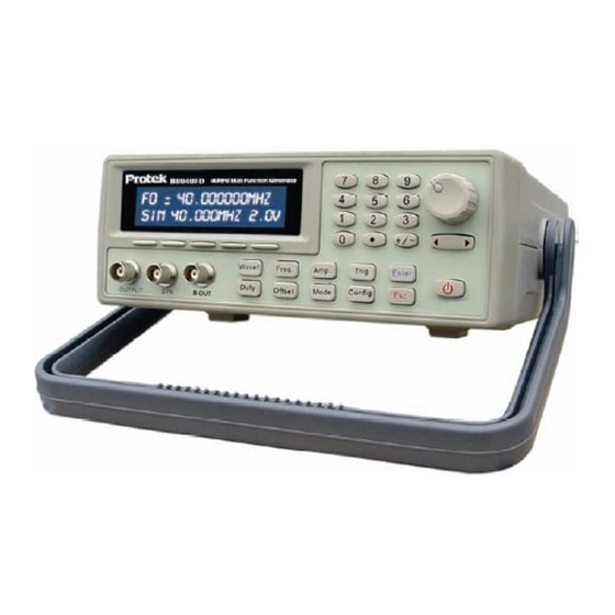
Related Manuals for Protek B8000FD Series


Summary of Contents for Protek B8000FD Series
- Page 1 B8000FD Series DDS Function Generator Operators Manual...
-
Page 2: Table Of Contents
Contents 1 Introduction....…………………………………………………1 1.1 Introduction…………….……………………………………….1 1.2 DDS Technology.……………………………………………..1 1.3 Product Series………………………………………………….2 1.4 General Information……………………………………... …..2 1.4.1 Contents……..…………………………………………….…2 1.4.2 Safety…..…………………………..…………………………2 2 Unit description………………………………………………………..3 2.0 Front panel description.....…..…………………………..3 2.1 Front Panel Outputs….……..…………………………….……3 2.2 Rear panel inputs…………………………………………..…..4 2.3 Front panel controls…….…..………………………………..5 2.4 Front panel button description………….……………………..7 3 Using the front panel buttons………………………………..……...8 3.1 Waveform..……………………….………………………...8 3.2 Frequency………………...…………………………….…….9... - Page 3 4.9 Internal Am modulation……………………………………19 4.10 External AM modulation………………………………….20 4.11 Demo……………………………………………………….20 5 Multifunction menu…………………………………………………..21 5.1 Config button………………………………...…………….21 5.2 B out ……………….………………………………………21 5.3 Frequency counter……………………………………..…22 5.4 RS232………………………………………………………23 6 External Trigger……………………………….……………………...24 6.1 Trigger button………………………….…………………..24 6.2 Single trigger…………………………………………...….25 6.3 External trigger…………………………………………….25 7 Store/Recall……………………………………………………………26 Appendix technical Specifications ….…………………………..27...
-
Page 4: Introduction
1 Introduction 1.1 Introduction The B8000FD series Digital Synthesized Function generator have the following features: DDS technology for excellent frequency stability, frequency resolution and the ability to generate very low frequencies. Very precise Sine, Square, triangle, Ramp, Exponential, Pulse and Sin (X)/X... -
Page 5: Product Series
1.3 Product series There are four models to choose from in the B8000FD series of DDS function generators with frequency ranges from 1μHz to 40MHz. These models include: Model B8003FD B8010FD B8020FD B8040FD Frequency 3MHz 10MHz 20MHz 40MHz All models are easy to use and generate Sine, Square, Triangle, Ramp, Exponential up, Exponential down, Pulse, sin (x)/x and noise waveforms. -
Page 6: Unit Description
Do not apply voltage to the output connector. Do not apply voltage over 10V to the input connector. . Do not use or store this instrument in a location near heat source or in a place subject to high humidity. This instrument should only be serviced by a competent electronics technician 2 Unit Description... -
Page 7: Rear Panel Inputs
same frequency as the selected waveform at the main output terminal and is used for synchronizing external equipment to the generator. For Sweep, the SYN signal is high during the time the waveform is sweeping and low during the inactive time the waveform is waiting for the next sweep to start. -
Page 8: Front Panel Controls
(11) (12) (13) (14) (15) (16) 2.3 Front Panel controls The front panel controls consists of: 1) The Numeric keyboard which is used to enter waveform data (Frequency, amplitude, offset and Duty cycle.) and the various modulation parameters as will be explained later. 2) The encoder knob is a Rotary digital encoder used to set values for the selected waveform parameter such as amplitude, phase, frequency, etc. - Page 9 example, continuous (CW) which is displayed adjacent to mode is the currently selected item. Pressing the soft button corresponding to > displays the next group of modulations. Mode: Continuous > Fig 2: 4) The front panel keys are of 3 types. The first is the single function buttons that...
-
Page 10: Front Panel Button Description
2.4 Front panel button description: "Mode": When pressed displays the modulation option menus. "Config": This key when pressed selects the B OUT put, Frequency Counter and RS232 menus. "Trig": When Burst, ASK, PSK or FSK modulation has been selected (see chapter on the Trigger functions), pressing the “Trig”... -
Page 11: Using The Front Panel Buttons
ESC key will return the display to the previous value. Soft buttons These keys are located at the bottom of the LCD display and are used to select in items in the "Mode" or "Config" menus. The five buttons are have a corresponding menu item assigned to them item and selects this item when pressed (See fig 2). -
Page 12: Frequency
which is 3MHz). All other waveforms have a upper frequency limit of 1MHz. Exceeding these limits will cause the waveform to be distorted. WAVEFORM: 1.0000 kHz 1.00V Fig 3 3.2 Frequency (Freq) Pressing the "Freq." button displays the frequency menu similar to what is shown in Fig 4. -
Page 13: Amplitude
Encoder knob clockwise while the frequency unit is blinking will cause the frequency to increase by a factor of 10. Rotating the Encoder knob counter clockwise will decrease the frequency by a factor of 10. Example: If the currently selected frequency is 1.0000000 KHz and the KHz units is blinking, rotating the encoder clockwise 1 step will increase the frequency to 10.000000 KHz. - Page 14 the amplitude value with a digit blinking along with the amplitude units. The new amplitude value will be entered here. Note: The displayed amplitude is in volts peak to peak in to a 50Ω load with an amplitude range of 1.00mV to 10.0 Volts for the models with frequencies of 20 MHz or less (1.00mV to 3.00V for the model B8040FD) The lower portion of the LCD displays the currently selected...
-
Page 15: Duty Ratio
digits are blinking, pressing the Esc key will return the amplitude value to its previous value. AMPLITUDE = 100. 1.0000 kHz 100mV Fig 5 3.4 Duty ratio (Duty) Pressing “Duty” button displays the Pulse Duty ratio menu on the LCD as shown in figure 6. The top portion of the LCD displays the Duty ratio value with a digit blinking along with a % symbol. -
Page 16: Mode Button
on the LCD as shown in figure 7. The top portion of the LCD displays the offset value with a digit blinking along with a % symbol. The new Duty ratio value is entered here. The Offset value may be entered using the encoder dial or the keyboard as explained in the paragraphs on Frequency and Amplitude. - Page 17 displays the next group of modulations as shown in Fig 9 Mode: Continuous < burst > Fig 9 Figure 9 shows the menu for selecting Phase shift key (psk), Amplitude shift key (ask) and Burst modulations and their corresponding soft button. Pressing the soft button that corresponds to the <...
-
Page 18: Modulation Setup Menus
Mode: Continuous < extam Demo Fig 11 demo as shown in fig 11 4 Modulation set up menus The following paragraph will explain the various modulation menus and the parameter that are needed to be set. 4.1 Linear sweep Pressing the soft button corresponding to the linear sweep the menu as shown in fig 12 is displayed on the LCD. -
Page 19: Log Sweep
Pressing the soft button that corresponds to F1, the Start frequency will be displayed on the top line of the menu as shown in Fig 13. The start frequency and all other parameters are set and entered using the Encoder dial and the keyboard as explained on page 9 and page 11 on how to set the generator frequency and amplitude. -
Page 20: Frequency Shift Key
F1: Start frequency F2: Stop frequency Tw: Sweep time Ts: the time when the next sweep starts OK: Confirms the settings and starts the sweep 4.3 Frequency shift keying: Pressing the soft button corresponding to FSK displays the menu as shown in figure 15 MODE: Fig 15 F1: frequency 1... -
Page 21: Amplitude Shift Key
Tw: the 0 phase shifted signal working time Ts: the phase shifted signal working time OK: Confirms the settings and starts the waveform 4.5 Amplitude shifting keying MODE: Fig 17 Fo: Carrier frequency Ph: Carrier phase shift Tw: Carrier frequency duration Ts: the time the next waveform starts OK: Confirms the settings and starts the waveform 4.6 Burst (Pulse waveform) -
Page 22: Phase Modulation
Fo: Carrier wave frequency Fm: Modulating wave frequency (modulation) Fd: Max frequency deviation (deviation) Wa: Modulating waveform (wave) Ok: Confirms the settings and starts the waveform 4.8 Phase modulation MODE: internal Fig 20 Fo: Carrier wave frequency Fm: Modulating wave frequency (modulation) Pd: Max phase deviation (deviation) Wa: Modulating waveform (wave) OK: Confirms the settings and starts the waveform... -
Page 23: External Am Modulation
4.10 External AM modulation MODE: external < extam demo Fig 22 The External amplitude modulation has no parameter setup menu. Selecting extam in the Mode menu enables the External modulation input located on the rear panel of the instrument. The modulating waveform from an external signal or function generator can be applied to this input. -
Page 24: Multifunction Menu
oscilloscope. This mode may be also used when 2 signals of the same frequency but have different phases is needed for an application. 5 Multifunction menu 5.1 Config button Pressing the "Config" button displays Multi funct menu as shown in Fig 24. When this key is pressed the LCD displays the items that may be selected. -
Page 25: Frequency Counter
Fa: selects the Frequency Ampl: selects the Amplitude OK: Confirm the new setup and starts the B OUT The B OUT is an auxiliary low frequency DDS function generator capable of outputting all waveforms as described above and can be used as the modulation generator for the Ext AM mode. -
Page 26: Rs232
range for better stability. When the frequency of the input signal is greater than 100 kHz, use the "100KHz to 1 00MHz" range to prevent errors. 5.4 RS-232 RS-232, 9600, N,8,1 quit Fig 27 RS-232, 9600, N,8,1: 9600 Baud rate, no parity bit; 8 bit data; 1 bit stop. -
Page 27: External Trigger
FREQ1000 Sets the frequency to 1000Hz The range is from 0.001 to15,000,000 VOLT100 Sets the amplitude to 100mV, the range is 1mV to 10,000mV DUTY50 Sets the pulse ratio to 50% duty ratio. The duty ratio range is 20% to OFFSET0 Set the DC of set offset to 0%. -
Page 28: Single Trigger
side of the LCD. If the “MODE" key has been pressed, the word "MODE" will change to "MODE (T)". 6.2 Single trigger When in the signal trigger mode, every time the "Trig" button is pressed the generator will output one SWEEP, FSK, PSK, ASK or BURST waveform. -
Page 29: Store/Recall
duration To exit the trigger mode, press the "Esc" button. The “trig" symbol will disappear in a non modulation mode or the (T) in a modulation mode and the instrument will return to the internal trigger mode. 7.0 Store /Recall (B8040FD) --- STORE/RECALL--- Memory: Fig 29... -
Page 30: Appendix Technical Specifications
Appendix SINE, SQUARE, TRIANGLE, RAMPUP, Function RAMPDOWN, NOISE, SIN(X)/X, EXPUP, Waveform EXPDOWN, PULSE Sine wave: 1μHz to the upper limit Square wave: 1μHz to 5MHz Other waveforms: 1μHz to 1MHz Maximum resolution: 0.1μHz or 8 digits Frequency Long term stability: 50ppm (0°C to 40°C ) Characteristics Short term stability: 1ppm (after 20 minutes of warm up) - Page 31 Linearity (1kHz):<0.1% Amplitude: into an open circuit): 2mVpp to 6Vpp(B8040FD) 2mVppto 20mVpp (All other units) ( to 50 Ω): 1mVppto 3Vpp (B8040FD) OUTPUT 1mVpp to10Vpp (All other channel units) Characteristic Output impedance: 50 Ω Modulation flatness: 5% Sine wave flatness: 5% DC offset: -100%to 100% peak-peak Waveform: internal waveforms Amplitude (open circuit): 200mVpp to 20Vpp...
- Page 32 Phase: -360 to 360 degree Burst pulse: 1 to 65535 Carrier waveform: All internal waveforms (except square wave) Carrier waveform frequency: 1Hz to upper limit Internal Frequency resolution: 0.4Hz amplitude Modulation waveform: All internal waveforms modulation Modulation frequency: 100mHz to 20kHz Modulation frequency stability: 50ppm Modulation depth: 0%to100% External...
- Page 33 Technical specifications Specifications are subject to changes without notice.
- Page 34 Protek Test & Measurement 45 Smith Street, Englewood, NJ 07631, USA Tel: +1-201-227-1161 Fax: +1-201-227-1169 Email: sales@protektest.com http://www.protektest.com...
Need help?
Do you have a question about the B8000FD Series and is the answer not in the manual?
Questions and answers