Table of Contents
Advertisement
Quick Links
Advertisement
Table of Contents

Related Manuals for Protek C3100


Summary of Contents for Protek C3100
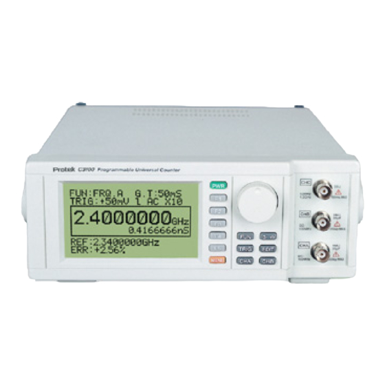
- Page 2 Programmable Universal Counter...
- Page 3 Safety rules to using his device Safety Regulations 1. Do not touch any part of high voltage circuit or make any unnecessary measurements. Do not remove the top or bottom covers of this unit unless you are a qualified service person. Remove the power from this unit before removing the top and bottom covers.
-
Page 4: Table Of Contents
Contents Chapter 1. General specification 1. Product summary............... 1 2. General specifications ............... 1 3. Electrical specifications ............. 2 4. Accessories ................4 Chapter 2. Installation of the equipment 1. Initial inspection ................. 5 2. Preparation for use ..............5 3. -
Page 5: Chapter 1. General Specification
Chapter 1. General specification 1. Product summary This programmable frequency counter is one of a series of programmable test instruments that has enhanced features over similar type of test instruments on the market today. This instrument features: 1) High accuracy frequency measurement to 2.4 GHz. 2) Nine measurement functions: FRQ. -
Page 6: Electrical Specifications
3. Electrical Specifications Note: Electrical specifications are at 25°C. 1) CHA, CHB input characteristics ▪ Freq. Range :0 to 120Mhz(DC Coupled) 10Hz to 120MHz(AC coupled) ▪ Sensitivity: 25mV rms (Sine Wave ) ▪ Impedance : 1Mohm less with less than 35pF capacitance ▪... -
Page 7: Accessories
▫ Coupling: AC ▫ Accuracy: ±Time Base Error ±1 Count (3) Time Interval (A ▫ Input: Channel A and B ▫ Measurement range: 0.5uS to 0.2S (5Hz to 2MHz) ▫ Pulse width: 250nS minimum ▫ Resolution: 0.1uS Max ▫ Accuracy: Time Base Error ± CHA Trigger Error ± Magnification ±1 Count (4) TOT. - Page 8 This unit is shipped with the following accessories: 1) Manual·························································································· 1 copy 2) BNC cable ······················································································ 1 unit 3) Line Cord ························································································ 1 unit 4) Spare fuse (2A, 250V) ···································································· 1 unit 5) RS232 Cable (9Pin to 9Pin) ··························································· 1 unit 6) RS232 Program··············································································...
-
Page 9: Chapter 2. Installation Of The Equipment
Chapter 2. Installation of the equipment This chapter supplies all the necessary information to install this equipment. It includes: initial inspection, preparation for use, appropriate voltage selection, packing for the return, etc. 1. Initial inspection 1) When received, inspect the shipping box for damage. If the shipping carton is damaged verify that there is no mechanical damage to the instrument and it is functional. -
Page 10: Chapter 3. Product Description
Chapter 3. Product description In this chapter, the front and rear panel buttons, controls and connectors are described. 1. Front Panel buttons and connectors description [Figure 1] Front Panel 1) CHC input BNC Input for measuring frequencies from 100MHz to 2.4GHz. 2) CHB input BNC Input for measuring frequencies from 0 to 120MHz and is used along with CHA for measuring Time interval (A B), Ratio (A/B) and Difference... - Page 11 FRQ.B TOT.A DTY.A FRQ.C F3 Press F3 Press RPM A F4 F5 Button F4 F5 Button ⇒ ⇒ More ▼ More ▼ EXIT [Table 1] Fun Button layout Button Toggles the cursor between the selection mode cursor displayed as a (< or >) symbol and the edit mode cursor displayed as a (◀...
- Page 12 Pressing this button for 1.5 to 2 second will turn the unit on. Pressing this button again for 1.5 to 2 seconds will turn the power off. 12) [F1, F2, F3, F4, F5] Buttons These buttons have a corresponding menu item displayed on the LCD when the MENU, CHA, CHB or FUN, buttons are pressed.
-
Page 13: Rear Panel
2. Rear Panel [Figure 3] Rear Panel CAUTION Before using, check that the AC line voltage is within the specified line voltage range. 1) AC input The AC line cord is inserted in to this connector. The allowable AC voltage range is 85V to 270Vac (±10%), 48 to 66 Hz. - Page 14 Standard IEEE-488 connector for connecting multiple devices to the GP-IB interface. * Note The total cable length should be less than 25m(80ft) and the maximum number of device connections (including controller) is 15. ◈ GP-IB Example Figure 4 is an example of connecting multiple devices to the GP-IB port. [Figure 4] GP-IB (Example of connecting the connector)
-
Page 15: Chapter 4. Lcd, Front Panel Buttons And Menus Description
Chapter 4. LCD, Front panel buttons and menus description 1. LCD display description Displays Section 1-TOP DISPLAY The current setup values and the selection/edit cursor Displays Section 2-MAIN-DISPLAY The measured values or Pass/ fail when in the compare mode Displays: •... - Page 16 1) Cursor (1) The cursor is displayed in the upper part of the LCD when the unit is first turned on as shown in Figure 5. It is used to indicate and change counter settings and functions. When the cursor is displayed as a (< or >) symbol it is the selection cursor and can be moved from one menu item to another by turning the rotary dial.
- Page 17 4) TRG: (Trigger Level) ▣ Displays the current Trigger level value. ▣ The range of the TRIG LEVEL is : ±1.28V as a scale from -99 to +99 units ▣ To change the current TRIG level: press Button to display the selection mode cursor (<...
- Page 18 The current measured frequency value is displayed or PASS/Fail when in the compare (COMP) mode. 10) Period display: Displays the period (1/F) of the currently displayed frequency measurement. (HOLD): This symbol is displayed when the [HOLD] button is pressed. The LCD reading is “frozen” until this button is press again 12) Data from one of the following (PROG) program modes is displayed in this area of the LCD: (1) MAXIMUM and MINIMUM frequency values when REC (record mode) is...
- Page 19 (3) HI and LO limit values in the COMPARE (COMP) mode. To select COMP press the following button sequence MENU PROG(F1) COMP (F3). This mode compares the input frequency to a high and low frequency limit value. A LO is displayed if the input frequency is lower than the low limit, PASS if the input frequency is within the high and low limit values and Hi if the input is greater than the high limit.
-
Page 20: Menu Description
2. MENU description This section explains the items in the menus and sub menus and the F soft buttons [F1], [F2], [F3], [F4], [F5] for selecting items in the menus. Table 4 is the diagram of the Menu structure that is displayed when the MENU button is pressed. - Page 21 1) MENU Description [F1] PROG (Program mode): REC(record), REL(relative), COMP (comparison), NONE and EXIT sub menus are displayed. [F2] TREND: Displays the trend graph with the reference value as the centerline. [F3] SETUP: Displays a list of a settings, data values and the PAGE, SAVE, LOAD, NEXT, EXIT soft Keys for selecting a memory page, saving the current screen or recalling a previously saved counter setup screen.
- Page 22 [F1] SET UP: The Reference frequency, horizontal and vertical axis values (REF, H/Div, V/Div) are displayed. The REF is the centerline value on the trend graph, H/Div is the X axis (time) and V/DIV is the Y axis (amplitude). Pressing the EDIT button and following the procedure on pages 14 or 19 for editing digit values, the REF, V/Div and H/Div values may be entered or changed.
- Page 23 (1) SETUP menu displays the current counter settings, Reference frequency, Compare HI limit and Compare Lo limit values. Pressing the NEXT (F4) button advances the display to the next menu screen; exit returns the display to the normal screen. Selects memory page address: 0 to 7 ♦...
-
Page 24: Rotary Dial
(3) To edit numerical data (Relative Reference, HI/LO Comp) values: (a) Turn the rotary dial to indicate the data value to be changed with the selection cursor (<). (b) Press the button to select the edit cursor (◄). (c) Turning the rotary dial the cursor changes to a ( ) symbol and highlights a digit or label (HZ, KHz, etc). -
Page 25: Quick Reference Guide
1) The Rotary dial is used to move the selection cursor (< or >) from one item to another in the top section of the LCD or in the set up menu. It changes the value of the settings when it is indicated by the edit cursor (◄ or ►). It is also used to change numerical data (Relative frequency or HI/LO frequency limit values) when REL or COMP program modes are selected or in the setup menu. -
Page 26: Chapter 5. Using This Instrument
Chapter 5. Using this instrument 1. Preliminary setup 1) Check whether the AC input voltage is within the specified range before turning the unit on. See [Figure 3]. 2) Connect the AC power cord to the receptacle on the rear panel. 3) Turn on the power by pressing the [PWR] button for 1.5~2 seconds. - Page 27 (a) Press the edit button to display the selection cursor (< >) and turn the rotary dial until it indicates G.T: __ (b) Press the to select the edit mode cursor (◄). Turn the rotary dial until the appropriate gating time is displayed on the LCD, and then press the button.
- Page 28 (a) Press MENU PROG (F1) REL (F2) buttons. (b) Press the EDIT button to display the selection cursor (<) (c) Press the , button to display the edit cursor (◄). When the rotary dial is turned the cursor changes to a ( ) symbol and highlights a digit.
-
Page 29: Counter Function Descriptions
3. Counter Function descriptions The 9 functions performed by this instrument and how to use them are explained in this section. These functions include: 1) FRQ A (1) Enables the CHA input to receive an input signal and is used in conjunction with the FRQ B input for time interval (A B) and frequency ratio A/B measurements. - Page 30 (2) To select the FRQ C input, press the FUN button and then the [F3] button. (3) The MIN/Max or Relative (REL) frequency is set up the same way as explained in steps (2) and (3) of FRQ A. 4) Time interval (A(B) (1) Time interval measures the time between a starting event on CHA and a stop event on CHB.
- Page 31 6) Ratio A/B (1) This function measures the ratio of the signals applied to the CHA and CHB inputs. (2) To select Ratio A/B press the FUN MORE (F5) F3 (A/B) buttons (3) Apply the signal levels to the CHA and CHB inputs. NOTE: the frequency range of CHA is 10MHz to 120MHz and the CHB frequency range is 0.1MHz to 10MHz.
-
Page 32: Program Examples
9) RPM A (1) The RPM is equal to the Frequency/60. The maximum RPM that can be measured is 600,000RPM (2) Select RPM A by pressing the FUN MORE(F5) MORE(F5) [F3] buttons. (3) Connect the signal source to the CHA. input (4) The trigger level, coupling, gate time, slope and LPF are set up the same way as explained in Steps1a and b of FRQ. - Page 33 Figure 11A (1) The reference frequency value is centerline as shown in Figure 11B. The Horizontal divisions in the example are 40 seconds per divisions. The H/Divisions may be set from 20S/Div to 5Hrs/DIV. The V/DIV may be set to any frequency and depends on the desired resolution; in this example the V/DIV is 2kHz/Div.
- Page 34 (a) Press the Press the . Button to display the selection cursor (<). Turn the rotary dial to indicate H/DIV. (b) Press the . Button to select the Edit cursor (◄) and turn the rotary dial to select the desired H/DIV. (c) Press the EXIT [F5] button when finish with the set up to return to the Trend graph.
-
Page 35: Rs232C Interface
Instrument and to the PC serial port. 5) Communication with PC (1) Start the program by clicking the mouse on the PROTEK C3100 icon (2) Click on the SetUp Button to open the setup dialog. Then select appropriate Serial Port and Baud Rate and click on the OK button.
Need help?
Do you have a question about the C3100 and is the answer not in the manual?
Questions and answers