Table of Contents
Advertisement
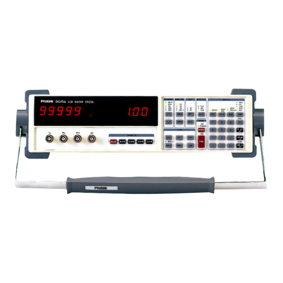
Z9216
S P E C I F I C A T I O N S
Measured Components
L (inductance)
C (capacitance)
R (resistance)
Measured Circuit Configurations:
Measurements
Resistance
Measured Parameter:
R + Q
Measurement Ranges:
R: 0.0001 Ω to 2000 MΩ
Q: 0.00001 to 50
Inductance
Measured Parameter:
L + Q
Measurement Range:
L: 0.0001 µH to 99999 H
Q: 0.0001 to 50
Capacitance
Measured Parameters:
C + D and C + R
Measurement Range:
C: 0.0001 pf to 99999 µF
D: 0.00001 to 10; R: 0.00001 KΩ to 9999 KΩ
Display:
Values, % deviation, or bin number
Test Environment
Test Frequencies:
100Hz, 120Hz, 1kHz, 10kHz and 100kHz
Frequency Accuracy:
±100 PPM
Drive Voltages:
Fixed: 0.10, 0.25, 1.0 V RMS;
Vernier: 0.1 to 1.0 V RMS (50 mV resolution)
Drive Voltage Accuracy:
±2%
Protek Test & Measurement
40 Boroline Road, Allendale, NJ 07401 Tel: 201-760-9898 Fax: 201-760-9888
30
Website: www.protektest.com E-Mail: sales@protektest.com
High Accuracy, Wide Range LCR Meter
0.2% basic accuracy
Wide measurement range over13 orders of magnitude
Store and recall 9 instrument setups
Measurement rates to 20 times per second
Test frequencies are 100Hz, 120Hz, 1kHz, 10kHz and 100kHz
Displays component value and Q or Dissipation factor
Averaging for 2 to 10 measurements
RS-232 and optional GPIB and Handler interface
Open and short circuit compensation for accurate zeroing
Easy to use and calibrate
Built-in calibration procedures
Binning capabilities
Measurement Rates:
(For test frequencies of 1kHz or greater):
Slow: 2 measurements/Sec
Medium: 10 measurements/Sec
series and parallel
Fast: 20 measurements/Sec
(For test frequencies of 100Hz and 120Hz):
Slow: 0.6 measurements/Sec
Medium: 2.4 measurements/Sec
Fast: 6 measurements/Sec
Bias Voltage:
External: 0 to +40 V DC
Input Protection:
Ranging:
Auto or manual
Triggering:
Continuous, manual or remote (from the RS-232,
GPIB or handler interface)
Measurement Accuracy
Basic Accuracy:
1. An ambient temperature of 23°C ±5°C after a 30 minute
warm up period.
2. The short and open Cal has been performed.
3. D < 0.1 for capacitance, Q < 0.1 for resistance and Q > 10 for
inductance.
The component value, measurement rate and frequency
determine the actual measurement accuracy. (See the user
manual).
Zeroing Correction:
Remote Operation:
conductor) Standard GPIB and Handler (25 pin D male
connector optional)
Z9216
Internal: +2.0 V DC ±2%;
0.25A/250V Fuse
± 0.2% with the following conditions:
Open and short circuit compensation
Interfaces: RS-232 (25 pin D female
CE
General Specifications
AC Voltage Input:
120/220 Volts
Frequency:
50/60Hz
Power Consumption:
20 Watts
Operating Temperature:
0 to 50°C at < 80% Relative Humidity
Size:
4.3" H × 14.3" W × 14.5" D
Weight:
18 lbs.
Supplied Accessories:
Manual, Line cord, Axial lead adapter
Optional Accessories:
GPIB and Handler interface, Kelvin
clips, SMD tweezers
Advertisement
Table of Contents

Related Manuals for Protek Z9216


Summary of Contents for Protek Z9216
- Page 1 Open and short circuit compensation Remote Operation: Interfaces: RS-232 (25 pin D female conductor) Standard GPIB and Handler (25 pin D male connector optional) Protek Test & Measurement 40 Boroline Road, Allendale, NJ 07401 Tel: 201-760-9898 Fax: 201-760-9888 Website: www.protektest.com E-Mail: sales@protektest.com...
- Page 2 The standard accessory supplied with the Z9216. This The Kelvin clips provide a 4-wire connection to The SMD tweezers are used to unit adapts to the Z9216 input BNC terminals and components that have large or odd shaped leads. This measure small surface mount or odd...
- Page 3 Mouser Electronics Authorized Distributor Click to View Pricing, Inventory, Delivery & Lifecycle Information: Protek Z9216...
-
Page 5: Background On Components And Measurements
Background on Components and Measurements Properties of Resistors, Inductors, and Capacitors The measurements made by the Model Z9216, Digital LCR Meter are based on the definitions of impedance and the properties of discrete components designed to provide impedances in electronic circuits. - Page 6 In this situation of positive, imaginary impedance, the impedance is purely inductive, as an ideal inductor would be. The impedance of an ideal inductor with inductance L is a linear function of = jωL. frequency, given by Z If the phase of the voltage is 90 degrees (π/2 radians) behind the phase of the current, then the impedance is a negative imaginary number: −...
-
Page 7: Series And Parallel Equivalent Circuits
Series and Parallel Equivalent Circuits The impedances of Actual resistors, inductors and capacitors are combinations of resistance, inductance, and capacitance. The simplest models for actual inductors and capacitors are the series and parallel equivalent circuits shown in Figure 1-1. For example, the complex impedance of an inductor is ω... -
Page 8: Quality Factor
Quality Factor Originally, the quality factor, Q was defined for an inductor as a measure of the efficiency of energy storage in the inductor when an AC current is passed through it. Mathematically, the definition is Q = 2π (max. energy stored) ÷ (energy dissipated per Hz) (10a) = 2π... - Page 9 Using the quality factor, the impedance of an inductor is seen to be ω ω (13a) and the inductor’s series equivalent circuit components can be expressed in terms of its parallel equivalent circuit components as (13b) The impedance of a capacitor in terms of the quality factor is ω...
-
Page 10: Accuracy And Calibration
Accuracy Specifications Note: The accuracy of the Model Z9216 that is stated in this chapter is valid for the following conditions: (a) a warm-up time of at least 30 minutes, (b) a temperature of 23°C ± 5°C, (73°F± 9°F) (c) the use of the built-in fixture, and (d) the completion of the open and short circuit calibrations. - Page 11 .55% .35% .55% .35% .25% .35% 0.20% Figure 2-1 Basic Impedance Accuracy Table 2-1 - Integration Time Accuracy Factor, K Meas. Rate Frequency Slow, Medium Fast 100 Hz to 1 kHz 6.25 Ω < Z < 400 kΩ All other Table 2-2 - -Drive Voltage Error Factor, K Vout (Vrms) 0.55 to 1.0...
-
Page 12: Accuracy Equations For Specific Measurement Modes
Table 2-3 - Extreme Range Error Terms For Impedance and Resistance, K and K Frequency 100 Hz, 120 Hz, 1 kHz (1 mΩ/Z /2 GΩ) 10 kHz (1 mΩ/Z /1.5 GΩ) 100 kHz (4 mΩ/Z /50 MΩ) Accuracy Equations for Specific Measurement Modes R + Q Accuracy In the R + Q measurement mode, the basic impedance accuracy, Az, in equation (1), may be read from Figure 2-1 directly while interpreting the “impedance”... - Page 13 Then the accuracy of the Q calculation is given by equation (3b) Accuracy of Q = ± [(A /100) × (1+Q (3b) 0.55% 0.35% 0.55% 0.35% 0.25% 0.35% 0.20% Figure 2-2 Basic Impedance Accuracy for Inductance Table 2-4 - Extreme Range Error Terms for Inductances, K and K Frequency 100 Hz, 120 Hz...
- Page 14 C+D Accuracy The basic impedance accuracy depicted in Figure 2-1 applies to capacitance measurements when the impedance is interpreted to be 1/2π f C, where f is the test frequency in Hz and C is the capacitance in Farads. For convenience, Figure 2-1 is redrawn in Figure 2-3 with lines of constant capacitance superimposed.
- Page 15 Table 2-5 Extreme Range Error Terms for Capacitances (C + D mode), K and K Frequency 100 Hz, 120 Hz (2 pF/C /1600 mF) 1 kHz (0.1 pF/C /160 mF) 10 kHz (0.01 pF/C /16 mF) 100 kHz (0.02 pF/C /200 µF) Note: C m = Measured Capacitance Value...
- Page 16 For D > 0.1, the impedance accuracy must first be calculated. To do this, first calculate the impedance of the DUT by adding the resistive and capacitive elements, either in series or parallel, as appropriate. Use the impedance accuracy graph to obtain an impedance accuracy, and let it be denoted A .
- Page 17 Table 2-8 - Parameters for Calculating K and K for Inductive Measurements × L × L Frequency 1 µH 20 µH 300 µH 100, 120 Hz 5 mH 630 H 10 kH 160 kH 2.6 MH 1 µH 20 µH 300 µH 1 kHz 5 mH...
-
Page 18: Verification Of Meter Performance
The performance verification procedures in this section test and verify the performance of Model Z9216 and compare it to the specifications listed in Volume 1 of the User’s Manual. The first set of tests verifies the basic functionality of the unit. - Page 19 This test checks the Model Z9216 output voltage for the correct frequency and amplitude. 1. Set the Model Z9216 to 1 kHz, 1 V and constant voltage. Set the scope to 1 V/div vertical and 0.5 ms/div horizontal. Connect a ×10 probe to the scope.
-
Page 20: Capacitance Measurement
(100 ppm) of the nominal value. 1. Set the Model Z9216 to its default conditions by pressing the key sequence RCL 0 ENTER. Set the unit to constant voltage mode, 1 kHz test freqency, and remove any part from the fixture. - Page 21 0.102, respectively). Record the results. 5. Set the DVM to DC volts. Set the Model Z9216 to the C+D measurement mode, 100 kHz test frequency, 0.10 V drive voltage with internal Bias on. Verify that the DC voltage is 2.0 VDC ±...
- Page 22 4. Set the decade resistor and the Model Z9216 according to the values in the Resistance Accuracy Table below. Verify that the readings fall within the acceptable values. Record the results. Resistance Accuracy Table Range Conditions Minimum Maximum Resistance 10.0Ω...
- Page 23 Connect the IH and PH leads to the “+” terminal of the decade capacitor. Connect the IL and PL leads to the "−" terminal of the decade capacitor box. Set the Model Z9216 to its default conditions by pressing the key sequence RCL 0 ENTER, then select the R+Q measurement mode and the 1 kHz test frequency.
-
Page 24: Calibration Procedures
The standard resistor calibration sets the accuracy of the Model Z9216, since it allows the LCR meter to determine the values of its internal standard resistors. The Standard Resistor Calibration need only be performed periodically to account for component aging and drift. - Page 25 Table 2-10 - Organization of Amplitude Calbytes to Amplitude and Frequency Amplitude Frequency 100 Hz 120 Hz 1 kHz 10 kHz 100 kHz 0.10 V 0.15 V 0.20 V 0.25 V 0.30 V 0.35 V 0.40 V 0.45 V 0.50 V 0.55 V 0.60 V 0.65 V...
-
Page 26: Amplitude Calibration
DVM. Do not connect either end to ground. Set the meter to AC volts, autoranging. Set the Model Z9216 to its default conditions by pressing the keys, RCL 0 ENTER. Set the unit to constant voltage mode. - Page 27 The clock correction factor is stored in parts per million (ppm). 1. Set the Model Z9216 to its default conditions by pressing the keys RCL 0 ENTER. Set the unit to constant voltage mode at 1 kHz, and remove any part from the fixture.
- Page 28 In addition, the Model Z9216 and the calibration resistors must be placed in a temperature controlled room and allowed to stabilize at least 30 minutes before attempting calibrate.
-
Page 29: Remote Control Of The Lcr Meter
Remote Control of the LCR Meter Remote Programming Reference The Model Z9216 LCR meter may be controlled and programmed remotely using either an RS-232 or the optional GPIB (IEEE488) interface. Any computer supporting either of these interfaces may be used with the Model Z9216. Both interfaces are simultaneously active and are accessed via the connectors on the rear panel. - Page 30 Table 3-1 - RS-232 Signals and Pin Assignments Signal Direction Description — Protective Shield Ground → Transmit data ← Receive Data → Request to Send ← Clear to Send ← Data Set Ready — System Ground ← Carrier Detect RESERVED RESERVED →...
- Page 31 CTS/DTR hardware handshaking discussed above. The CTS signal (pin 5) is an output of the meter indicating that the Model Z9216 is ready, while the DTR signal (pin 20) is an input to the meter that is used to control the Model Z9216 transmissions. If desired, the handshake pins may be ignored and a simple three-wire interface (pins 2, 3 and 7) may be used.
- Page 32 Optional GPIB (IEEE 488) Interface (Model Z9216-4 Only) The IEEE-488 Interface Standard The General Purpose Interface Bus (GPIB), also known as the IEEE-488 interface, is an 8-bit parallel bus common on test equipment. The IEEE-488 standard was proposed by Hewlett-Packard in the late 1970s and has undergone several revisions.
- Page 33 Table 3-3 - GPIB (IEEE-488) Connector and Pin Assignments Signal Description 1 to 4 DI01 to DI04 Data lines. End or Identify. The Talker uses the EOI to mark the end of a message string, while the Active Controller uses it to tell devices to identify their responses in a parallel poll.
-
Page 34: Mechanical Description
A timing diagram for the handler interface is shown in Figure 3-1. In the states labeled (a) in the figure, the Model Z9216 is waiting for a trigger to start measuring. Previous bin data, if any, is still available on the data outputs. - Page 35 Figure 3-1 - Handler Interface Timing Diagram. Table 3-4- Pinout for Handler Interface Connector Signal Signal -START +5 supply +5 supply -BDA -BUSY Bin 9 Bin 8 Bin 7 Bin 6 Bin 5 Bin 4 Bin 3 Bin 2 Bin 1 Bin 0...
-
Page 36: Using Commands
There is no need to wait between commands. The Model Z9216 has a 256-character input buffer and processes commands in the order received. If the buffer fills up, the Model Z9216 will hold off handshaking on the GPIB and attempt to hold off handshaking on RS232. - Page 37 Table 3-5 - Examples of Command Formats 2 <LF> Sets the drive frequency to 100 Hz (one-parameter command) FREQ ? <LF> Queries the drive frequency (query of one-parameter command Sets the upper limit of bin 3 to 1000 Ω (three-parameter command BLIM 0, 3, 100 <LF>...
- Page 38 Performing a Remote Calibration and Hardware Test via RS232 or GPIB Many automated setups require frequent open and short circuit calibrations. The Model Z9216 allows the user to perform open and short circuit calibrations remotely so that no external interference is required.
-
Page 39: Status Displays And Error Messages
The ERR LED flashes when an error has been detected, such as an illegal command, or parameter out of range. The REM LED is lit whenever the Model Z9216 is in a remote state (front panel locked out). - Page 40 Standard Event Name Usage Set by the OPC command when all measurements are complete Not used Query Error Set on output queue overflow (too many responses waiting to be transmitted.) Not used Execution err Set by an out of range parameter, or non-completion of some command due a condition such as an incorrect operating mode.
-
Page 41: Binning Options
Binning Using the LCR Meter to Sort Components The Model Z9216 has built in features to aid in component sorting, which is useful for production testing, incoming inspection, device matching, or tests in which multiple components of similar value must be measured. The binning feature simplifies parts sorting by eliminating the need to read the major and minor parameters and then deciding what to do with the part. -
Page 42: Nominal Value
Nominal value −4% −3% −2% −1% Bin 0 Bin 1 Bin 2 Bin 3 Figure 4-1 - Example of Nested Bins Sequential Bins With Different Nominal Values Suppose that the batch of nominally 100 Ω resistors is to be sorted according to actual value instead of according to tolerance, as in the previous example. -
Page 43: General Procedures
Sequential Bins With a Single Nominal Value Suppose that the batch of nominally 100 Ω resistors is to be sorted according to tolerance, as in the first example, but with the ability to distinguish between the low and high values. Then the bins can be set up to have the same nominal values, with each bin having asymmetric limits that are expressed as a percentage of the nominal value: 95 Ω... -
Page 44: Setting Up The Bins
Table 4-1 - QDR Limits and Extreme Values Measurement Mode QDR Limit Extreme Value R + Q Q maximum 9999.9 L + Q Q minimum C + D D maximum 9999.9 C + R series R maximum 99999 C + R parallel R minimum Setting Up the Bins Procedures... - Page 45 Values for Fail Bins 8 and 9 To set the QDR limit value, select Bin 8 (using the keys BIN# 8 ENTER) and press the NOM key. This action will generate a display of the present QDR limit, or “----“, in the right alphanumeric display and turn on the NOM LED.
-
Page 46: Summary Of Binning Setups
Table 4-2 - Binning Worksheet Date: Nominal Value of Component: Tolerance to be sorted to: Entered by: Type of binning: Pass/Fail Nested Sequential Bin # +lim -lim ----- ------ ----- ----- ----- Summary of Binning Setups Pass/Fail Setup Enter the nominal value and limits for Bin 0. Enter the QDR fail value for Bin 8. Make sure no other bins are open (set their limits to zero). -
Page 47: Troubleshooting
Chapter Troubleshooting General Problems Nothing Happens at Turn-on Make sure that the power entry module on the rear panel is set for the AC line voltage for your region, that the correct fuse is installed, and that the line cord is inserted all the way into the power entry module. -
Page 48: Error Messages
Error Messages The following lists explain all of the error messages that the Model Z9216 can generate. The messages are divided into operational errors (errors in using the instrument), self-test errors, and calibration errors. The messages are listed alphabetically. Operational Errors These error messages may appear during normal front-panel operation and generally are warnings for incorrect operation. - Page 49 Data Error CPU RAM failed a read/write test. Det Error The square wave multiplier failed its DC rejection test. Drv Error i The output drive circuitry failed its test. i is an error code indicating the failure point. error 100 Hz amplitude failure 120 Hz amplitude failure 1 kHz amplitude failure 10 kHz amplitude failure...
- Page 50 The default GPIB address is 17, so it is a good idea to use this address when writing programs for the Model Z9216. Any address from 0 to 30 may be set using the rear panel switches SW2.
- Page 51 Model Z9216 Test Performance Record Serial #: Date: Tested By: Equipment Used: Model#: RH %: Temperature: Notes: FUNCTIONAL TESTS Pass Fail Test Values Front Panel Test Self Test Drive Voltage Resistance Test 24.9 Ω +/- 0.15% 402 Ω +/- 0.15% 6.34 kΩ...
- Page 52 IMPEDANCE ACCURACY Minimum Actual Maximum 1.000 KΩ +/- 0.02% 999.3 Ω 1000.7 Ω RESISTANCE ACCURACY Range Conditions Minimum Actual Maximum Pass/Fail Resistance 10.0Ω 1kHz, Series 25.0Ω 1kHz, Series 25.0Ω 10kHz, Series 25.0Ω 100kHz, Series 100.0Ω 1kHz, Series 100.0Ω 1kHz, Series 400.0Ω...
Need help?
Do you have a question about the Z9216 and is the answer not in the manual?
Questions and answers