Table of Contents
Advertisement
Quick Links
Advertisement
Table of Contents

Subscribe to Our Youtube Channel
Related Manuals for Protek A734


Summary of Contents for Protek A734
- Page 2 This Operating Manual represents design, specifications, overview of functions, and detailed operation procedure of Protek A734 Spectrum Analyzer, to ensure effective and safe use of the technical capabilities of the instruments by the user. Spectrum Analyzer operation and maintenance should be performed by qualified engineers with initial experience in operating of microwave circuits and PC.
-
Page 3: Table Of Contents
INTRODUCTION ....................... 2 SAFETY INSTRUCTIONS ................10 GENERAL OVERVIEW ................... 15 Description ..................18 Specifications ..................19 Options and Accessories ..............23 Principle of Operation ................27 PREPARTION FOR USE .................. 30 Power Adaptor ..................30 Battery....................31 Front Panel ..................37 Top Panel ..................... - Page 4 4.4.5 Detector(F5) ................116 4.4.6 Ref. Clock(F6) ................ 119 Marker ....................122 4.5.1 Marker(F1) ................125 4.5.2 Normal(F2)................126 4.5.3 Delta(F3) ................130 4.5.4 Off(F4) ................... 135 4.5.5 Marker CF(F5) ..............136 4.5.6 Marker All Off(F6) ..............138 Trace ....................139 4.6.1 Trace(F1) ................
- Page 5 Figure Figure 2-1 A734 Hand-Held Spectrum Analyzer ........18 Figure 2-2 A734 Option & Accessories ..........23 Figure 2-3 A734 Block-diagram ............27 Figure 3-1 Connecting the power adaptor ..........30 Figure 3-2 Battery ................. 31 Figure 3-3 A734 bottom view ............... 33 Figure 3-4 Battery Charger Cradle ............
- Page 6 Figure 4-45 Load Type Menu-tree ............222 Figure 4-46 Limit Line Menu-tree ............226 Table Table 2-1 A734 Specifications ............... 19 Table 2-2 Option & Accessory Descriptions..........24 Table 3-1 External Power Indicator LED ..........35 Table 3-2 Battery Charging Status LED ..........35 Table 3-3 Environment Specifications ............
- Page 7 Table 4-12 Span Menu Descriptions ............70 Table 4-13 Changing Set Span (with number keys) ....... 73 Table 4-14 Set Span Active & De-active ..........73 Table 4-15 Changing Span (Up/Down Key & Rotary knob) ....75 Table 4-16 Chancing Zero Span (number keys) ........80 Table 4-17 Zero Span Active &...
- Page 8 Table 4-50 Volume Control Step ............213 Table 4-51 Lo/Re Menu Descriptions ........... 214 Table 4-52 Preset Menu Descriptions ..........221 Table 4-53 Load Type Menu Descriptions ..........222 Table 4-54 Limit Line Menu Descriptions ..........226...
- Page 9 SAFETY OPERATING MANUAL INSTRUCTION...
- Page 10 The protection provided by the equipment may be impaired if the equipment is used in a manner not specified by the manufacturer. A734 is tested in stand-alone condition or in combination with the accessories supplied by GSI against the requirement of the standards described in the Certificate of Compliance.
- Page 11 following: Always use a desktop anti static mat under the DUT. Always wear a grounding wrist strap connected to the desktop anti static mat via daisy-chained 1 MΩ resistor. Observe all the general safety precautions related to operation of equipment powered by mains. The definitions of safety symbols used on the instrument or in the Manual are listed below.
- Page 12 Adaptor. The power connection plug must only be plugged into a two-pin grounded socket! Do not use any battery except for specified battery. Li-Ion batteries must not be exposed to high temperatures or fire. Keep batteries away from children. ...
- Page 13 Never use water or abrasives for cleaning any connectors of the Analyzer. Do not allow contact of alcohol to the surface of the insulators of the connectors. When connecting male-female coaxial connectors always use a calibrated wrench. Caution Never perform cleaning of the instrument if the power cable is connected to the power outlet.
- Page 14 +82-32-1688-6820 GS Instruments Co., Ltd. 70, Gilpa-ro 71beon-gil, Nam-gu, Incheon, 402-854, Korea Product Information and Technical Assistance www.gsinstrument.com isale@gsinstrument.com...
-
Page 17: General Overview
GENERAL OPERATING MANUAL OVERVIEW... - Page 18 A734 is Hand-Held type spectrum analyzer with a frequency range of 100 kHz to 4.4 GHz. This equipment is suitable for signal analysis which can be used as frequency, digital information are more important these days. A734 Hand-Held Spectrum Analyzer has been designed for use in the...
-
Page 19: Specifications
Protek A734 has wide frequency range of 100 kHz to 4.4 GHz and provides analysis ability which can measure low level RF signal with preamp. The equipment has low power consumption so that A734 can operate for 8 hours with the battery. - Page 20 10Hz -124dBm 100Hz to -130dBm 10kHz 10kHz to -142dBm 500kHz 500kHz to -142dBm -153dBm 10MHz 10MHz to -148dBm -161dBm 100MHz 100MHz to -144dBm -158dBm 1GHz 1GHz to -139dBm -151dBm 2.6GHz 2.6GHz to -135dBm -151dBm 3.3GHz 3.3GHz to -128dBm -134dBm 4.4GHz Amplitude unit dBm, Watt Absolute Accuracy...
- Page 21 DETECTOR min, max, sample, avg ( power , voltage , log ) Marker 5 Marker Marker function peak, next peak, center=marker frequency, Audio Demodulation AM & FM Type 5.7" Color TFT-LCD 640*480 pixels Display Resolution 640*480 pixels Feature SunLight Readable KeyPad Back Light ON/OFF Input...
- Page 22 ...
- Page 23 Figure 2-2 Options & Accessories...
- Page 24 Specification Description Picture...
- Page 25 Operating Manual PC GUI Manual Stereo 6FT(1.8MM) 220V BLACK AC Input: 100- 240V-,1.5A DC Output: 12Vdc, 5A Nominal Voltage: 7.4Vdc Capacity: 7800mAh DC Input: 12Vdc, 3A DC Output: 8.3Vdc, 2.5A...
- Page 26 Frequency Range : 20Mhz to 3.8GHz Sensor Type : Average Peak Power Sensor : -40dBm to +10dBm Accuracy : ±7% Test Port : Precision N Female...
- Page 27 A734 Spectrum Analyzer consists of the Analyzer Unit, and some supplementary accessories. The Analyzer Unit includes internal computer, display, and keypad. The block diagram of the Analyzer is represented in figure 3. Figure 2-3 A734 Block-diagram The Analyzer Unit consists of CPU module, carrier board, RF module, LCD, keypad board, rotary board, speaker, audio jack, battery, and AC/DC adaptor.
-
Page 29: Prepartion For Use
PREPARTION FOR OPERATING MANUAL... - Page 30 The Equipment uses following Power Supply. Product: Switching Power Supply Adaptor Model no. FSP060-DBAE1 AC INPUT: 100-240 V-, 1.5 A, 50-60 Hz DC OUTPUT: 12.0 Vdc 5.0A MAX Manufactured by: Zhonghan Electronics (Shenzhen) Trade mark: FSP GROUPINC ...
-
Page 31: Battery
A734 uses CE, UL certificated PBP-7800 Battery. Figure 3-2 Battery RISK OF EXPLOSIOM IF BATTERY IS REPLACED BY AN INCORRECT TYPE. DISPOSE OF USED BATTERIES ACCORDING TO THE MANUFACTURER’S INSTRUCTIONS. If the “push” button on the battery is pressed, the ... - Page 32 Avoid placing the battery pack near heating sources or on the place near windows. Do not store the battery pack in the high humidity. If the battery is unused for a long time, separate it from the unit. ...
- Page 33 Caution: Full charge the battery before first using the analyzer. Figure 3-3 A734 bottom view Open the battery cover. Insert the battery (Observe correct battery polarity orientation when installing). Close the battery cover.
- Page 34 If any of the monitored conditions exceed their safety limits, the battery will terminate any further charging or discharging until the error condition is corrected. Protek A734 has another battery charging method which uses Battery Charger Cradle. Figure 3-4 Battery Charger Cradle...
- Page 35 Product: Battery Charger Model no. C122R5 DC INPUT: +12Vdc(+11Vdc to +29Vdc) Manufactured by: GS Instruments Co., Ltd. The battery charger equipment is used to supply stable DC power to charge the external battery pack. The input voltage of battery charger equipment is +12 Vdc(+11 to +29 Vdc) and the output voltage of battery charger equipment is +8.3 Vdc ±...
- Page 36 Operating Temperature 0C-50C Full Load Condition Operating Humidity 0%-90%...
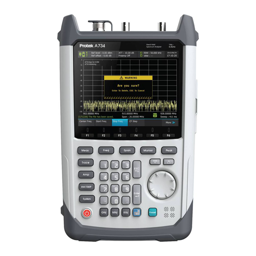
- Page 37 The front view of A734 is represented in figure 3-5. The front panel is equipped with the following parts: Figure 3-5 A734 Front View...
- Page 38 «POWER SWITCH» toggles between On and Off states of the Analyzer. Holding the key for more than 3 seconds on Note an operating Analyzer will turn off the power supply Do not disconnect the power cable from the CAUTION mains when the Analyzer is operating. This can damage the Analyzer software.
- Page 39 The assignment of functional hard keys is determined by a current soft key panel displayed along the upper side of the screen. The control keys enable you direct access to the control functions of the Analyzer. They allow the user to access a specific function by pushing just one key.
- Page 40 «ESC» key is used for the following: If there is an active data entry field, this key cancels all the data entered in the field and restores the value of the field as it was before any new numbers or characters were entered. If there is no active data entry field, this key ...
- Page 41 Using the alphanumeric keys, you can enter numeric values or characters. The alphanumeric keys include the numbers from 0 to 9, the alphabet, a minus sign and dot. Each key covers one number and more than one character with the first choice being a character.
- Page 42 «CAPTURE / BACK» key is used for the following: «CAPTURE» key is used to capture the screen. If there is an active data entry field, this key completes the entry process and assigns the new value to the field. «GHz»...
- Page 43 «UP» and «DOWN» CURSOR keys are used for the following: If there is an active numeric data entry field, these keys scroll up and down the list of the available numeric values. «UP» arrow increases the value, «DOWN» arrow decreases the value. The rotary knob is used for the following: ...
- Page 44 The top view of A734 is represented in figure 3-6. The top panel is equipped with the following parts: Figure 3-6 A734 Top View Accepts an external input with a frequency range from 100 kHz to 4.4 GHz. 0 VDC +20dBm MAX...
- Page 45 To use the self test, connect the SELF TEST to the INPUT. This checks the attenuator, mixers, broadband power detector, RF and IF signal paths, and I/Q demodulator DC 6V Max 10MHz Reference input, automatically detected after each sweep completes. Use a clean 10 MHz reference with >0 dBm level.
- Page 46 The side view of A734 is represented in figure 3-7. The side panel is equipped with the following parts: Figure 3-7 A734 Side View...
- Page 47 Provides input for the DC power source via an AC-DC adapter In case of emergency, to avoid danger of electric shock or the like, pull the power cable out of the power outlet or the DC power connector of the instrument.
- Page 48 Ethernet port allows the user to connect the Analyzer to a LAN (Local Area Network). This connection enables the user to control the instrument using an external PC 10BASE-T & 100BASE-TX CAT5e UTP Cable ...
-
Page 49: Operation And Function
OPERATION AND OPERATING MANUAL FUNCTION... - Page 50 Figure 4-1 Main Window Name Category Descriptions AC Power Icon - AC Power Adaptor connected - AC Power Adaptor disconnected...
- Page 51 Battery & Icon - Battery connected to AC power Charge - Battery full-charged - Operated with the battery - Remaining battery capacity is 90% or over - Operated with the battery - Remaining battery capacity is 8% or less - Battery is being charged - Remaining battery capacity is 90% or over - Battery is being charged...
-
Page 52: Freq (Frequency)
- RBW Auto setting - RBW Manual setting BW/SWP - Displays the Video Bandwidth value - VBW Auto setting - VBW Manual setting Date & Time - Displays the current date and time Text Status - Ext. Trigger: Displays the external trigger status - Single: Displays the single sweep status... - Page 53 The Freq (Frequency) control key allows you to change the frequency of the A734 for measurement. It is used to set the horizontal axis information of the screen and consists of Center Freq (F1), Start Freq (F2), Stop Freq (F3) and CF Step (F4). The Freq control key is located as shown in the following figure.
-
Page 54: Cf Step(F4)
You can view the current frequency in the main window. However, the sub menu of Freq provides the current frequency information at the bottom of each item. The allowed frequency range of A734 is from 100 kHz to 4.4 GHz and you should change the frequency within the given frequency. - Page 55 The Center Freq (F1) changes the center frequency without changing the span to measure. When entering to the Freq menu, the Center Freq is activated by default. Press the number key and the frequency input window will appear. Enter the center frequency and then press the Unit key to start sweep with to the same span and the changed center frequency.
- Page 56 While the Center Freq is activated, press the number key to display the input window. Enter the center frequency value and then press the Unit key to complete the setting. If pressing ‘Enter’ after entering the value, not pressing the Unit key, the unit is in Hz.
- Page 57 frequency input display the frequency input window. window (Press the first number of the center frequency to change) Enter the center Enter the center frequency with the number frequency value keys. Unit key or Enter ‘Enter’ key Sets the frequency in Hz as the center frequency.
- Page 58 Figure 4-4 Center Frequency Control (Up/Down Key & Rotary) Item Direction Description Lower The center frequency decreases as much as the CF Step (F4) setting value when the key is pressed once. 1 push Changes the center frequency to the value of Center frequency-CF Step.
- Page 59 Frequency display resolution. When you enter the frequency not supported by A734 or enter the start frequency higher than the stop frequency, a short message is displayed. The Start Freq (F2) sets the start frequency of the bandwidth to measure and sets the start point on the left end of the vertical axis in the main window.
- Page 60 Key Stroke Sequence Freq Start Freq(F2) Press the F2 key while the menu is the Freq menu.
- Page 61 While Start Freq is activated, press the number key to display the input window. Enter the start frequency value and then press the Unit key to complete the setting. If pressing ‘Enter’ after entering the value, not pressing the Unit key, the unit is in Hz.
- Page 62 Activated Deactivated The allowed range of start frequency is from 100 kHz to (Stop frequency+600 Hz). When you enter the frequency out of the range, a short message is displayed The Stop Freq (F3) sets the stop frequency of the sweep data to measure and sets the start point on the right end of the vertical axis in the main window.
- Page 63 Key Stroke Sequence Freq Stop Freq(F3) Press the F3 key while the menu is the Freq menu.
- Page 64 While Stop Freq is activated, press the number key to display the input window. Enter the stop frequency value and then press the Unit key to complete the setting. If pressing ‘Enter’ after entering the value, not pressing the Unit key, the unit is in Hz.
- Page 65 Activate Activate the Stop Freq (F3). Open the frequency While it is activated, press the number key input window to display the frequency input window. (Press the first number of the start frequency to change) Enter the start Enter the stop frequency with the number frequency value keys.
- Page 66 The CF Step (F4) is the only one item of which frequency is not affected by the changed setting. The CF Step (F4) sets the changing width of the center frequency per one pressing of the Up/Down key to adjust the center frequency.
- Page 67 While CF Step is activated, press the number key to display the input window. Enter the CF Step value and then press the Unit key to complete the setting. If pressing ‘Enter’ after entering the value, not pressing the Unit key, the unit is in Hz.
- Page 68 GHz. When you enter the frequency out of this range, a short message indicating the range error is displayed. When changing the center frequency after setting the CF Step, if you enter the frequency out of the range supported by A734, a short message indicating the range error is displayed.
- Page 69 Span is the sweep frequency range (Stop frequency ~ Start frequency), indicating the frequency range displayed on the screen. Therefore, when the span is changed, the sweep frequency range is changed, too. When the Span is changed, the current center frequency is fixed but the start frequency and the stop frequency are changed.
-
Page 70: Set Span(F1)
You can view the current span information in the main window. However, the sub menu of Span provides the current information at the bottom of each item. The allowed span range of A734 is from 0 Hz to 4.3999 GHz and you should change the span within the given frequency. - Page 71 The Set Span (F1) changes the current span. The Set Span (F1) changes the start frequency and the stop frequency based on the current center frequency. When entering to the Span menu, the Set Span (F1) is activated by default. Press the number key and the frequency input window will appear.
- Page 72 While Set Span is activated, press the number key to display the input window. Enter the span value and then press the Unit key to complete the setting. If pressing ‘Enter’ after entering the value, not pressing the Unit key, the unit is in Hz. To close the window without saving the setting, press the ESC key.
- Page 73 Activate Activate the Set Span (F1). Open the While it is activated, press the number key frequency input to display the frequency input window. window (Press the first number of the span to change) Enter the span Enter the span with the number keys. value Unit key or Enter ‘Enter’...
- Page 74 Figure 4-7 Span Control (Up/Down Key & Rotary) While the Set Span (F1) is activated, press the Up/Down keys and then the span will be changed in the 1-2-5 sequence. The 1-2-5 sequence indicates that the span is changed to the value which starts with 1, 2 or 5 and is lower or higher than the current span value.
- Page 75 ⋀ ⋁ The following table shows the change of Set Span(F1) with the Up/Down keys and the rotary knob. Item Ditection Description 1 push -> decreased the span in 1- Lower 2-5 sequence. 1 push -> increased the span in 1- Upper 2-5 sequence.
- Page 76 When you enter the span value not supported by A734, a short message is displayed. The Full Span (F2) changes the span to the current full span. Pressing the Full Span (F1) key changes the span within the range from 200 MHz to 4.4 GHz.
- Page 77 After applying the Full Span, the Set Span(F1) is activated as shown above. The range of Full Span of A734 should be specified to the value from 200 MHz to 4.4 GHz because of the sweep speed. If the frequency under 162 MHz should be swept, the RBW cannot be set to 5 MHz but to 250 kHz.
- Page 78 The Zero Span (F3) is to measure the change of frequency with 0 Hz span. Set the desired point as the center frequency and then execute Zero Span. The span is set to 0 Hz and the horizontal axis is changed to the Time axis. The length of the Time can be set within the range of 10 ~ 2000 ms and the default value is 20 ms.
- Page 79 While Zero Span is activated, press the number key to display the input window. Enter the time value and then press the ‘Enter’ key to complete the setting. To close the window without saving the setting, press the ESC key. When the Zero Span is set, narrow the span as much as possible to reduce the frequency error, increasing the accuracy.
- Page 80 Execute Zero Span (F3) (it Execute and activate Zero span should be activated) While it is activated, press the number key to display the time Open the Time input window input window. (Press the first number of the time to change) Enter the time with the Enter the time value number keys.
-
Page 81: Amp (Amplitude)
The Amp (Amplitude) allows you to change the Amplitude-related items of A734, the Y-axis on the screen. The Amp menu consists of Ref Level(F1), Scale/Div(F2), Unit(F3), Atten(F4), Preamp(F5) and Ref Offset(F6). The Amp key is located as shown in the following figure. -
Page 82: Ref Level(F1)
You can view the current amplitude information in the main window. However, the sub menu of Amp provides the current information at the bottom of each item. The maximum amplitude range of A734 is +20 dBm. To measure the signal larger than +20 dBm, you should connect an... - Page 83 The Ref Level(F1) sets the top value of the Y-axis on the screen. If the input signal is larger than the specified Ref Level, the trace shown on the screen cannot show the top value. Therefore, you need to set the Ref Level larger than the input signal.
- Page 84 While Ref Level is activated, press the number key to display the input window. Enter the reference level value and then press the ‘Enter’ key to complete the setting. If pressing ‘Enter’ after entering the value, not pressing the Unit key, the unit is in Hz.
- Page 85 Activate Activate the Ref Level(F1). While it is activated, press the number key Open the Ref Level to display the Ref Level input window. input window (Press the first number of the Ref Level to change) Enter the Ref Level Enter the Ref Level with the number keys.
- Page 86 Figure 4-10 Reference Level Control (Up/Down Key & Rotary) Item Ditection Description The Ref Level decreases as much as the Scale/Div(F2) setting value Lower when the key is pressed once. 1 push Changes the Ref Level to the value of Ref Level - Scale/Div.
- Page 87 The Ref Level increases as much as the Scale/Div(F2) setting value Upper when the key is pressed once. 1 push Changes the Ref Level to the value of Ref Level + Scale/Div. The Ref Level decreases as much as the Scale/Div(F2)/10 when the Counterclockwise key is pressed once.
- Page 88 The Scale/Div(F2) adjusts the width of the one grid on the Y-axis. To control this, it should be activated. When it is activates as shown below, it can be set by using the Up/Down keys or the rotary knob. The Scale/Div(F2) does not allow you to enter the value with number keys.
- Page 89 By default, the amplitude unit is dBm scale. However, for some users' convenience, Watts scale is provided in a limited range. As shown in the following figure, all amplitude items of A734 are in dBm scale. When Watts scale is applied, only the amplitude information of the marker, channel power and the power level of the ACP are displayed in Watts scale.
- Page 90 Key Stroke Sequence Amp Unit(F3) Unit os all Amplitude values are dBm by default.
- Page 91 When changed to the Watts scale, only the amplitude information of the marker and channel power is changed to Watts scale.
- Page 92 The Atten(F4) adjusts the internal attenuator size. To control this, it should be activated. When it is activates as shown below, it can be set by using the Up/Down keys or the rotary knob. The Atten(F4) does not allow you to enter the value with number keys.
- Page 93 the value is changed to 0.0 dB. In reverse, when the current value is 5.0 dB, press △ and then it is changed to 10.0 dB. Like the Up/Down keys, when rotating the rotary knob to the clockwise, the value is changed to the value higher than the current value. In reverse, when rotating the rotary knob to the counterclockwise, the value is changed to the value lower than the current value.
- Page 94 0dBm < Ref.Level ≤ 10dBm Sets Atten ≥ 10dB 10dBm < Ref.Level Sets Atten=15dBm The Preamp(F5) turns on or off the RF Preamplifier in A734. If the input signal is low, set the Preamp(F5) to On to increase the internal gain in the A734 for improved measurement sensitivity.
- Page 95 The default setting: Off Set when the input signal is high. Set when the input signal is low. Increase sensitivity and reduce LO feed-thru Set to On when the max. input signal is -20 dBm or lower. A Local Oscillator signal may be observed at the RF input port, often found 10.7 MHz above the RF frequency being scanned.
- Page 96 The Ref Offset(F6) sets the offset of the Y-axis on the screen. You can set it when the value should be compensated because of extension cable loss or connection of an external attenuator. When the Ref. Offset is set to the amplitude offset, the Y-axis is the value of Ref Level + Ref Offset and the offset is applied to the measured trace size, too.
- Page 97 While Ref Offset is activated, press the number key to display the input window. Enter the Ref Offset value and then press the ‘Enter’ key to complete the setting. To close the window without saving the setting, press the ESC key.
- Page 98 To change the reference offset, you can use the number keys. Up/Down keys and the rotary knob are not supported by the Ref Offset(F6). Changing Ref Offset by using number keys Activate Activate the Ref Offset(F6). While it is activated, press the number key Open the Ref Offset to display the Ref Offset input window.
-
Page 99: Bw/Swp (Bandwidth/Sweep)
The BW/SWP menu provides functions to set RBW/VBW, Detector mode, Sweep Type, Sweep Time and Ref. Clock. As shown below, click the BW/SWP key to change the F1 ~ F6 keys to BW/SWP functions. Figure 4-11 Bandwidth & Sweep Control Key Pressing the BW/SWP key changes the F1 ~ F6 keys BW/SWP functions as shown in the following figure. -
Page 100: Rbw(F1)
Figure 4-12 BW/SWP Menu-tree Item Select Description RBW(F1) Auto Automatically sets the RBW to the value saved internally as the span is changed. Manual Sets the available value among the RBW list according to the span. VBW(F2) Auto Automatically sets the VBW to the value saved internally as the span is changed. - Page 101 A734 has RBW values which can be set according to the span and the value can be changed and applied by using the Up/Down keys or the rotary knob.
- Page 102 Key Stroke Sequence BW/SWP RBW(F1) Automatically sets the appropriate RBW according to the span Operation: automatic setting...
- Page 103 Sets the RBW to the user-specified value Operation: Up/Down keys or Rotary knob As shown in the above table, press the RBW(F1) key repeatedly to set to Auto or Manual. When Auto is set, Auto is displayed and the font gets a little bit bigger as shown in the left figure.
- Page 104 The RBW can be controlled manually only when the RBW is activated and the setting is Manual. When deactivated, the RBW cannot be changed. Activated Deactivated As shown in the table below, you can change the RBW by using the Up/Down keys and the rotary knob while the RBW is activated.
- Page 105 The VBW is a low pass filter which processes the sweep data which have been filtered by RBW and Detector(F5). The VBW lowers the range of noise level change. The data before being filtered by VBW has a wide range of trace change (point to point size). However, after VBW, the data has a narrow range of trace change.
- Page 106 Automatically sets the appropriate VBW according to the RBW Operation: automatic setting Sets the VBW to the user-specified value Operation: Up/Down keys or Rotary knob In the Manual setting, the VBW value should not be larger than the RBW value; it should be always the same or the smaller value than the RBW value.
- Page 107 In the Auto setting, the VBW is automatically set to the same as RBW. In the Manual setting, the VBW can be changed by using the Up/Down keys and the rotary knob as shown below. Figure 4-14 VBW Control (Up/Down Key & Rotary knob) Like the RBW, the VBW can be controlled manually only when the VBW is activated and the setting is Manual.
- Page 108 Activated Deactivated As shown in the above table, you can change the VBW by using the Up/Down keys or the rotary knob while the VBW is activated as shown in the following table. Up/Down Key Rotary Action Sets the VBW to the value lower than the current value.
- Page 109 The SWP Type allows you to set the sweep type to Single Sweep, Continuous Sweep or External Trigger mode. Press the SWP Type(F3) key and the bottom menu is changed to the sub layer as shown in the following figure. The F6 Return is used to move to the upper layer. Continuous(F1), Single(F2) and Ext.Trigger(F3) indicate the trace status and you must set one from the three.
- Page 110 Key Stroke Sequence BW/SWP SWP Type(F3) Updates the trace according to the sweep. Displays the sweep data at the time of pressing the Single(F2) key. The trace is not updated any more.
- Page 111 The External Trigger is available only when Zero Span is activated. To set this function, you need to execute Zero Span with the desired frequency. Press the Ext.Trigger(F3) to set it and then connect the trigger signal to the A734 Ext.Trigger terminal.
- Page 112 Zero Span setting: Span Zero Span(F3) Ext. Trigger setting: BW/SWP Sweep Type(F3) Ext. Trigger(F3) Cable connection: 3.3V CMOS/TTL input Even if you have been set to the Ext. Trigger(F3) mode, the operation is Continuous sweep until the cable is connected.
- Page 113 The SWP Time can be set to three stages: Fast, Medium and Slow. The default setting is Fast. For more accurate measurement, you can set it to Medium or Slow. Press the SWP Time(F4) key to change the bottom menu to the lower layer menu as shown below.
- Page 114 Key Stroke Sequence BW/SWP SWP Type(F3) The sweep data is processed with the fastest speed. The sweep data is processed with the medium speed.
- Page 115 The sweep data is processed with the slowest speed. Sweep time is not applied at all conditions. Sweep time can be applied at the section that the VBW is smaller than 3.2 kHz. Therefore, when the VBW is larger than 3.2 kHz, the amount of sweep data collected is small and there is no change even if Medium or Slow is applied.
- Page 116 There are four ways to detect the A734 sweep data: Max, Min, Sample and Average. Among this, Average allows you to choose one of the three modes: Power, Voltage and Log. Press the Detector(F5) key to change the bottom menu to Max(F1), Min(F2), Sample(F3) and Average(F4) as shown below.
- Page 117 Default setting type Randomly extracts and displays the sweep data. VBW cannot be applied while the Sample is set Extracts and displays the largest value among the sweep data in the frequency area. Extracts and displays the smallest value among the sweep data points in the frequency area.
- Page 118 spectrum analyzer in log scale BW/SWP Detector(F5) Key Stroke Sequence Average(F4) Averages the amplitude information of the extracted data by using RMS. Used for RMS power measurement. Averages the amplitude information of the extracted data by using Voltage scale.
- Page 119 A734 provides the TCXO reference time base. Generally, the OCXO time base shows higher stability than the TCXO time base. A734 allows you to set external 10MHz time base when you need measurement results with high frequency accuracy or synchronization. Ref.Clock(F6) provides two options, Int(Internal) and Ext(External), and the default setting is Int.
- Page 120 Key Stroke Sequence BW/SWP Ref.Clock(F6) Uses the Internal time base.
- Page 121 Ext.Clock is set, if the cable connected to the terminal is removed without changing the setting to Int.Clock, A734 does not operate normally; sweep may stop or not according to the equipment setting status. Therefore, when the cable is removed, you must...
- Page 122 OK” short message is displayed. The Marker is used to check the amplitude and frequency information of a specific point on the trace. A734 provides five markers, M1 ~ M5. Each marker can be selected by pressing the Marker(F1) key and the selected marker status can be set.
- Page 123 Figure 4-17 Marker Control Key Press the Marker key to change the bottom menu F1 ~ F6 to the marker items and to set M1 to the center frequency. In other words, Marker(F1) is set to 1 and Normal(F2) is activated. After entering to the Marker menu, you can set the marker number and the status.
-
Page 124: Marker(F1)
Figure 4-18 Marker Menu-tree Item Select Description Marker(F1) 1, 2, 3, 4, 5 Selects one of M1 ~ M5. Sets the selected marker status to Normal(F2) Normal. Displays and changes the frequency. Sets the selected marker status to Delta. Delta(F3) Displays and changes the difference between the reference point and the Delta point. - Page 125 The Marker(F1) provides the function to select one from M1 ~ M5. A734 provides five markers. By pressing the Marker(F1), set the marker to one of 1 ~ 5 and then set the status to Normal(F2), Delta(F3) or Off(F4) by using the F2, F3 or F4 key.
- Page 126 The Normal(F2) is a general status of a marker, showing the frequency and amplitude information of the point. Select a number to be set as Marker(F1) and then press the Normal(F2) to set the marker on the center frequency of the trace. To move the maker, you can enter the frequency of the marker directly or use the Up/Down keys or the rotary knob.
- Page 127 While Normal(F2) is activated, press the number key to display the input window. Enter the marker frequency value and then press the Unit key or the ‘Enter’ key to complete the setting. To close the window without saving the setting, press the ESC key.
- Page 128 Set to Normal(F2) Set the selected marker status to Normal(F2). Press the number key while the status is set Open the Marker to Normal(F2) and then the marker input frequency input window will be displayed. (press the first window number of the marker frequency to be changed) Enter the marker Enter the frequency value where the marker...
- Page 129 Figure 4-19 Marker Control (Up/Down Key & Rotary knob) Item Ditection Description 1 push -> Moves the marker toward Lower the lower frequency by Span/10 1 push -> Moves the marker toward Upper the higher frequency by Span/10...
- Page 130 1 click -> Moves the marker toward the Lower lower frequency by 1 point 1 click -> Moves the marker toward the Upper higher frequency by 1 point The marker in Normal status can be moved from the start frequency to the stop frequency.
- Page 131 Key Stroke Sequence Marker Delta(F3) When the Marker 1 is set to Delta(F3), 1R and 1D are displayed on the center frequency. Regardless of sweep, 1R has the same amplitude and frequency. 1D is moved along the trace according to sweep. While Delta is activated, press the number key to display the input window.
- Page 132 To close the window without saving the setting, press the ESC key. Moves 1D to the location which is 10 MHz far from 1R. The marker information on the right top side shows the difference of frequency and amplitude between 1R and 1D. When the Delta is set as shown in the above figure, the difference of frequency and amplitude between the reference marker and the Delta marker is displayed on the right top side of the screen.
- Page 133 number of the Delta frequency to be changed). Enter the difference of frequency and Enter the Delta amplitude between the reference marker and frequency value the Delta marker Unit key Moves the Delta marker to the location with the entered frequency and Unit Unit key or Enter key information.
- Page 134 Figure 4-20 Delta Marker Control (Up/Down Key & Rotary knob) Item Ditection Description 1 push -> Moves the Delta marker Lower toward the lower frequency by Span/10 1 push -> Moves the Delta marker Upper toward the higher frequency by Span/10 1 click ->...
- Page 135 1 click -> Moves the Delta marker Upper toward the higher frequency by 1 point The Delta marker can be applied to the frequency out of the current span. However, when moving to the frequency out of the span, adjust the start frequency and the stop frequency.
- Page 136 Key Stroke Sequence Marker Off(F4) Select the marker to set to Off. Press the F4 key. The MarkerCF(F5) moves the frequency of the selected marker to the center frequency. After moving the marker, press the MarkerCF(F5) key to move the marker frequency to the center frequency with the same span.
- Page 137 Key Stroke Sequence Marker MarkerCF(F5) Moes the marker to the desired location.
- Page 138 After moving the marker, press MarkerCF(F5). The marker frequency is changed to the center frequency (with the same span). The Marker All Off(F6) sets the status of all markers from 1 to 5 to Off. You do not have to select the number. After executing this, all markers are Off(F4).
- Page 139 Press the Trace key and the bottom menus F1 ~ F6 are changed to the trace items. When the A734 is in the default status, the yellow trace is T1, the green is T2 and the purple is T3. Press the Trace(F1) key to select one from T1 ~ T3.
-
Page 140: Trace(F1)
Figure 4-22 Trace Menu-tree Item Select Description Trace(F1) 1, 2, 3 Toggles among T1 ~ T3 Updates selected trace Clear Write(F2) according to sweep. Updates each point of the Max Hold(F3) selected trace to the max. value according to sweep. Keeps selected trace... - Page 141 When T2, located on the green trace. When T3, located on the purple trace. The Trace(F1) allows you to select one from T1 ~ T3. A734 provides three trace types and the type can be selected by pressing the Trace(F1) key.
- Page 142 The default setting is T1 (yellow) and the status is Clear Write. Press the F1 key to select one from T1 ~ T3. Select the desired trace number and then set the status by using F2-F6. As shown in the above figure, the current T1 (yellow) is in the Clear Write(F2) status.
- Page 143 Key Stroke Sequence Trace Clear Write(F2) T1 (yellow) is the Clear Write status by default. After selecting the number in the Trace(F1), activate it with the F2 key. If all of the status of T1 ~ T3 are Clear Write(F2), the trace displayed in the screen are overlapped.
- Page 144 The Max Hold(F3) compares each point of trace according to the sweep with the previous amplitude value and updates the value to the larger one. After RF sweep has ended, when the amplitude of the point is larger than the previous value, the previous amplitude is replaced with the current sweep data.
- Page 145 sufficient time period according to the sweep speed. When the configuration such as the frequency is changed in the Max Hold(F3) status, the Max Hold(F3) is reset. At this time, when the F3 key is pressed again, Max Hold is started from the moment that the key is pressed.
- Page 146 The Hold(F4) holds the selected trace as the trace when Hold is set. In other words, when Hold is executed while it is in the Clear Write status, the trace with the sweep data at the time of executing Hold is kept. Like that, when Hold is executed while it is in the Max Hold status, the trace with the sweep data at the time of executing Hold is kept.
- Page 147 Different from Clear Write or Max Hold, in Hold, the trace is not updated according to the sweep. Therefore, Hold is used to keep a specific trace without update. In the Hold(F4) status, the trace is kept even though the configuration such as Span is changed.
- Page 148 All of T1 ~ T3 are set to the Off(F5) status (all are Off, there is no trace displayed on the screen.) After selecting the number in the Trace(F1), activate it with the F4 key. The Off just remove the displayed trace from the screen, not stops sweep.
- Page 149 The following figures show that Count(F2) is set to 20 and Average(F1) is On, and the Count(F2) input window is open. Key Stroke Sequence Trace Average(F6) The default value is Off When it is set to On, each point of the trace is averaged as many times as the count set in the Count(F2).
- Page 150 While Count(F2) is activated, press the number key to display the input window. Enter the count (1 ~ 20) and then press the ‘Enter’ key to complete the setting. To close the window without saving the setting, press the ESC key.
- Page 151 Figure 4-24 Peak Control Key When the Peak key is pressed, the bottom menu is changed to the Peak menu. The following table shows functions of each menu. Figure 4-25 Peak Menu-tree...
-
Page 152: Peak
Name Enable Description - Runs like a HW key. - Sets the marker on the highest Peak Search(F1) amplitude point among the sweep data. - Moves to the amplitude point smaller Next Peak(F2) than the amplitude point of the current marker. - Among the sweep data, moves the frequency of the highest amplitude PeakCF(F3) - Page 153 The Peak Search(F1) is to search the highest amplitude point on the trace. When it is executed, the marker is placed on the highest amplitude point. When pressing the Peak key, Peak Search is immediately executed. Pressing the Peak key gives the same result with pressing the Peak Search(F1).
- Page 154 Sets the marker on the highest amplitude point on the screen. Several traces are set on the screen, sets on the current trace. When a marker is set, the marker is moved to the peak point. The Next Peak(F2) moves the marker to the amplitude point which is smaller than the amplitude of the marker.
- Page 155 Key Stroke Sequence Peak Next Peak(F2) After Peak Search...
-
Page 156: PeakCf(F3)
Moves the marker to the point of which amplitude is next highest on the screen. Several traces are set on the screen, sets on the current trace. The PeakCF(F3) is to change the peak point to the center frequency and to set the marker on the point. - Page 157 Before PeakCF(F3) Moves the highest amplitude point to the center frequency and then sets the marker on the peak point.
- Page 158 A734 provides useful measurement functions. You can view and select the functions by pressing the Meas key. The following figure shows the location of the Meas key. Figure 4-26 Measure Control Key The Meas menu consists of Measure Off(F1), Ch Power(F2), ACP(F3), Harmonic(F4), Phase Noise(F5), Demod(F1) and Pwr Sensor(F2).
-
Page 159: Measure Off(F1)
Figure 4-27 Measure Menu-tree Name Select Description Measure Off(F1) - Turns off the measure function. - Measures the channel power of the Ch Power(F2) bandwidth. - Measures the ACP with the ACP(F3) bandwidth and channel space. - Measures the 2 harmonic by using Harmonic(F4) the 100 kHz signal adjacent to the... - Page 160 The Measure Off(F1) removes the measurement functions which have been set. If Ch Power(F2), ACP(F3), Harmonic(F4), Phase Noise(F5), Demod(F1) and Pwr Sensor(F2) are set and you want to release the functions, press Measure Off(F1) to remove all functions. The following figure shows execution of the Measure Off(F1).
- Page 161 The Ch Power(F2) measures the power of the modulated signal. After setting the frequency defined in several communication standards and the channel bandwidth and then providing signals, the measured result is displayed. When the Ch Power(F2) is executed, the channel power is measured with the default setting and the bottom menu is changed to the channel power items.
- Page 162 Key Stroke Sequence Measure Ch Power(F2) Execute Ch Power(F2) to measure the channel power with the default (Span/5) channel bandwidth. You should change the channel bandwidth to the desired value.
- Page 163 While Ch BW(F1) is activated, press the number key to display the input window. Enter the channel bandwidth and then press the Unit key or the Enter key. To close the window without saving the setting, press the ESC key. Different from the Normal screen, the channel bandwidth is colored in blue in the Channel Power mode and the channel power of the area is displayed at the bottom.
- Page 164 Channel power mode window description Basically, the Detector should be set to Average-Power in the Ch Power(F2) mode. If the Detector is set to Sample, VBW is not applied. So the swing width gets larger and the accuracy gets lower. Causing the power measurement result lower by about 3 dB than the result when the VBW is set.
- Page 165 The ACP(F2) measures the Adjacent Channel Power (ACP) of the modulated signal. After setting the frequency defined in several communication standards and the channel bandwidth, you can view the signal ratio of the carrier channel and the adjacent channel. When executing the ACP(F3), the ACP is measured with the default setting and the bottom menu is changed to the ACP items.
- Page 166 You should change the channel bandwidth and the channel space to the desired values. While Ch BW(F1) is activated, press the number key to display the input window. Enter the channel bandwidth and then press the Unit key or the Enter key.
- Page 167 key. To close the window without saving the setting, press the ESC key. The ACP mode is similar to the Channel Power window. The channel bandwidth and the channel space are colored in blue in the ACP mode and the channel power of the area is displayed at the bottom. The left and right blue areas display the absolute value measured and the power difference from the carrier channel.
- Page 168 Sample, VBW is not applied. So the swing width gets larger and the accuracy gets lower. Causing the power measurement result lower by about 3 dB than the result when the VBW is set. Therefore, the Detector should be set to Average-Power when measuring the channel power or ACP.
- Page 169 Key Stroke Sequence Measure Harmonic(F4) Set the Peak point to the center frequency and then execute Harmonic(F4) The left five grids show the carrier signal and the right five grids show the 2 harmonic signal. Each marker tracks the peak value. The left top side shows the difference between the carrier peak amplitude and the 2 harmonic peak amplitude.
- Page 170 The Phase Noise(F5) measures the phase noise characteristics of the signal measured. To measure it, the conditions should be set as follows. Trace 1 Clear Write & Average Off Span ≤ 10kHz | Ref.Level – Peak Level | ≤ 10dB (Ref.Level control) ...
- Page 171 Execute Phase Noise(F5) after setting the conditions as follows. Trace 1 Clear Write & Average Off Span ≤ 10kHz | Ref.Level – Peak Level | ≤ 10dB (Ref.Level control) Peak to Center frequency Displays the result of measuring 100 Hz ~ 100 kHz phase noise. When executing Phase Noise(F5), the Notice window for the conditions is displayed.
- Page 172 Figure 4-30 Demodulation Menu-tree When executing AM(F1) and FM(F2) and a marker is Off as shown in the following figure., the marker is on the center frequency and the marker information on the right top shows the demodulation type and the frequency.
- Page 173 Before executing Demod(F1), place the marker on the frequency which requires demodulation or on the center frequency. After setting the frequency, execute the Demod(F1). The FM(F2) is set by default. Press the AM(F1) and then AM demodulation is executed and sound is output from the speaker (or earphone). Before executing Demod(F1), place the marker on the frequency which requires demodulation or on the center frequency.
- Page 174 Return(F6) click Marker or Center frequency change Demod(F1) click Select AM(F1) or FM(F2) In the demodulation status, the volume is adjusted by using the Up/Down key or the rotary knob. The volume level is 5-level. Pwr Sensor(F2) can be used when it is connected to the Power Sensor (optional).
-
Page 175: Pwr Sensor(F2)
Power Sensor dBm, Unit(F3) - Sets the measurement unit Watts Initialization(F4) - Power Sensor initialization Sensor Info (F5) - Power Sensor information display When the Pwr Sensor(F2 is executed while the Power Sensor is not connected, the following Notice window appears. - Page 176 Key Stroke Sequence Measure More(F6) Pwr Sensor(F2) Screen when execution is successful. The Power Sensor input port is open, no measurement result exists. The measurement range is from +10dBm to -40dBm. The result out of the range is displayed as --.—dBm. The following figure describes each part of the Pwr Sensor(F2) screen.
- Page 177 The Power Sensor is connected with A734 via USB. A734 uses the USB type interface with the other modules in the device. Therefore, if the A734 power is turned on/off after the Power Sensor has been connected, an error may occur because of the USB recognition sequence.
- Page 178 When the Power Sensor executes measurement, the A734 function keys do not operate. Therefore, you should control the span or frequency of A734 after the power sensor completes measurement. The information is displayed as a short message. The Freq(F1) sets the frequency to be measured by the power sensor.
- Page 179 Freq(F1) Activated When Pwr Sensor(F2) is executed, Freq(F1) is activated by default. While Freq is activated, press the number key and the input window appears. Enter the frequency value and then press the Unit key to complete the setting. To close the window without saving the setting, press the ESC key.
- Page 180 The Offset(F2) compensates the loss in the cable between the power sensor and the measured object. The input range is from -50dB to +50dB. When the value is out of the range, a short message is displayed. When Offset is set, the measurement result is compensated with the offset and the power is displayed on the main screen.
- Page 181 While Offset is activated, press the number key and the input window appears. Enter the frequency value and then press the Enter key to complete the setting. To close the window without saving the setting, press the ESC key. When Offset is set, the result compensated with the offset is displayed on the main screen.
- Page 182 Measure More(F6) Pwr Sensor(F2) Key Stroke Sequence Unit(F3) Power sensor measurement result is displayed in the dBm scale.
- Page 183 Power sensor measurement result is displayed in the Watts scale. It is like A734 Preset. When executed, it is changed to the default setting. Default setting means the frequency and offset are set to initial state. Frequency: 1GHz Offset: 0.00dB...
- Page 184 The Sensor Info(F5) shows the information of connected sensors. It provides the model name, FW version information, serial number, etc. Measure More(F6) Pwr Sensor(F2) Key Stroke Sequence Sensor Info(F5) When it is executed, it shows the power sensor information as shown above.
- Page 185 The System provides functions to control items except measurement and sweep. It allows you to save the measured data, the screen or the configuration or to adjust the IP, time or LED brightness. When a new SW is released, it allows you to upgrade it. And you can set either of local or remote through the System menu.
-
Page 186: File(F1)
- Sets time, IP, sound, light - Sets either of Local operating or Lo/Re(F3) Remote operating S/W Upgrade(F4) - Software Upgrade Information(F5) - Provides information on A734 Preset(F1) - Sets the Preset key operation Limit Line(F2) - Sets the items related to Limit line... - Page 187 USB. If it is set to Int, the file is saved or loaded in internal memory. When the USB memory is connected to A734, it takes a little time. The sub menus of File(F1) are shown in the following figure. The following table...
- Page 188 Figure 4-34 File Menu-tree Name Select Description - Saves the items related to Config, Save(F1) Screen and Trace - Loads the Config file and the screen Load(F2) file among the saved (Save(F1)) files - Renames, deletes or copies the saved Manager(F3) file Memory(F4)
- Page 189 Key Stroke Sequence System File(F1) Click the File(F1) and the bottom menu is changed as shown in the above. Press the F1 ~ F3 keys to move to each sub menu. Press F4 to set the target. The max. number of files which can be saved is 150, including Config, Screen and Trace.
- Page 190 The Save(F1) consists of Config(F1), Screen(F2) and Trace(F3). The Config(F1) saves the configuration as a file. The Screen(F2) saves the screen at the time of clicking it. The Trace(F3) saves the trace data at the execution time as a csv file. The following figures show Save(F1 sub menus and execution of Config(F1), Screen(F2) and Trace(F3).
- Page 191 Press the Screen(F2) and the file name input window will appear as shown in the above. The default setting is time as shown above, however, you can change it by using the keypad. To complete save, press the Enter key. To cancel the setting, press the ESC key.
- Page 192 Select a file by using the Up/Down keys or the rotary knob and then press the Enter key to change the A734 setting with the saved configuration. The Screen(F2) shows all screen capture files saved in the target memory. Select a file by using the Up/Down keys or the rotary knob and then press the Enter key to change the main screen with the saved screen capture screen.
- Page 193 Press the Config(F1) and the configuration file saved in the target memory is displayed. Select a file to load by using the Up/Down keys or the rotary knob and then press the Enter key. To cancel the setting, press the ESC key. Press the Screen(F2) and the screen capture file saved in the target memory is displayed.
- Page 194 The Manager(F3) consists of Rename(F1), Delete(F2), Delete All(F3), CopyUSB(F4) and CopyAllUSB(F5). Press the Manager(F3) key to open the file manager window. In this window, select the file to rename, delete or copy by using the Up/Down keys or the rotary knob and then click the F1 ~ F5 keys to execute the menu.
- Page 195 When executing Delete(F2), Delete All(F3), CopyUSB(F4) or CopyAllUSB(F5) after selecting the file from the file manager window, it is executed after a short message or a warning window is displayed. When executing Rename(F1), the following file rename window appears. System File(F1) Manager(F3) ...
- Page 196 To cancel it, press the ESC key. After completing copy, a short message is displayed. A short message is displayed when the USB has not been connected. The Memory(F4) sets the system memory target. You can select either of Internal memory and USB memory. Press the F4 key to toggle the target. Key Stroke Sequence System ...
- Page 197 Acter connecting the USB memory, toggle to USB and then the system memory target is changed to USB. When the setting is set to USB without connecting the USB memory, a Notice window is displayed as shown below. Press the Enter key or the ESC key to close the window.
- Page 198 The Setting(F2) sets or controls additional items of the equipment. Date/Time(F1) is used to set the time. Sleep Time(F2) is used to set the sleep mode entry time. LCD Bright(F3) and Key Light(F4) are used to control the screen brightness and key LEDs. IP Set(F5) is used to set the equipment IP.
- Page 199 Key Stroke Sequence System Setting(F2) Click Setting(F2) and the bottom menu is switched as shown in the above. Press F1 ~ F5 key to move or control to each sub menu. Sound(F1) is shown by pressing the More(F6). The Date/Time(F1) sets the date and time of the equipment. Date/Time(F1) consists of Date(F1) and Time(F2).
- Page 200 the format or range, it is not set. Date/Time(F1) menu and functions are as follows. Figure 4-39 Date/Time Menu-tree Name Select/Range Description Date(F1) - Sets the system date 8 digit Time(F2) - Sets the system time 4 digit Key Stroke Sequence System ...
- Page 201 input window. Enter the year, month and date in the window and then press the Enter key to complete the setting. To cancel the setting, press the ESC key. Press the Time(F2) and then the number key to display the time input window.
- Page 202 The Sleep Time(F2) sets the time that the equipment enters into the sleep mode. The Sleep mode is generally used to save the battery power. A734 minimizes or turns off LCD, keypad LED, system clock and sweep in the Sleep mode to minimize the power consumption. If the Sleep mode is not necessary, set Sleep Time(F2) to 0.
- Page 203 10 minutes, A734 enters into the Sleep mode. In the Sleep mode, A734 stops LCD, Key pad LED, System clock and Sweep to save the energy. When Sleep Time(F2) is set to 0, the Sleep mode is released.
- Page 204 LCD Bright(F3) adjusts the LCD backlight brightness. It is used to make the screen brighter or darker to reduce the power consumption. The range is 0 ~ 100 and the unit is %. When it is set to 0%, the LCD backlight is the darkest status.
- Page 205 The above figure shows LCD brightness 80%. When the battery is used, LCD brightness can be set to the low value to save the power. The Key Light(F4) turns on or off the key pad LED. In the dark place, the key pad silk is not clearly recognized.
- Page 206 Key Stroke Sequence System Setting(F2) Key Light(F4) The default setting is key light On. When it is set to On, the key pad LED is turned on and the key silk is visible in the dark place.
- Page 207 Press the Key Light(F4) to switch the status to Off (toggle between On and Off) When it is set to Off, the key pad LED is not turned on even when the keys are used. The IP Set(F5) sets the equipment IP and it must be set when Ethernet is used to connect to the equipment.
- Page 208 Key Stroke Sequence System Setting(F2) IP Set(F5) Press the IP Address(F1) and then the number key to display the input window. Enter the value in the IP field and then press the Enter key to complete the setting. To cancel the setting, press the ESC key.
- Page 209 IP setting is not required for local operation; however, it must be set for remote operation. Remote operation is available only when the IP setting of A734, the IP setting of the remote PC and the IP setting of the remote program are...
- Page 210 The Sound(F1) controls the sound output of the equipment. You can set the overall volume and key beep output. The sub menus are Volume(F1) and Key Beep(F2) and the functions are as follows. Figure 4-41 Sound Menu-tree Name Select/Range Description Volume(F1) - Sets the system volume.
- Page 211 Set it to On to output the beep when pressing the key pad buttons. When an earphone is connected to A734, all sounds including key beep, demodulation and limit line beep are output via the earphone. When the earphone is disconnected, the sound is output through the speaker.
- Page 212 Figure 4-42 Volume Control (Up/Down Key & Rotary knob) Item Ditection Description 1 push -> The volume decreases by one Lower level. 1 push -> The volume increases by one Upper level. 1 click -> The volume decreases by one Lower level.
- Page 213 1 click -> The volume increases by one Upper level. The volume image is changed according to the level. 0(Mute) The Lo/Re(F3) sets local operating and remote operating. The default setting is local and it is for local operation. To operate the equipment remote, the mode should be changed by using the Remote(F2).
- Page 214 Figure 4-43 Local & Remote Menu-tree Name Select/Range Description Local(F1) - Default setting. Local operating Remote(F2) - Remote operating Key Stroke Sequence System Lo/Re(F3) Default setting, normal operation...
- Page 215 Operation interworking with the remote GUI The LCD displays Remote Mode and all keys except the F1 key and the Power key cannot be operated. When switching between Remote and Local, the following warning window appears. Enter the Enter key to complete switch, or press the ESC key to cancel the setting.
- Page 216 The S/W Upgrade(F4) upgrades the equipment S/W when a new firmware is released. Copy the firmware (*.tar file) downloaded from the web site to the root folder of the USB memory. Connect the USB to the A734 USB terminal and press the S/W Upgrade(F4) to display the upgrade warning window.
- Page 217 window. At this time, press the Enter key to upgrade with the file. The equipment is automatically rebooted. When the upgrade has been successfully completed, a short message shows OK. To cancel the upgrade, press the ESC key in the warning window. S/W Upgrade(F4) can be executed only when the USB memory has the firmware.
- Page 218 Press the Information(F5) to view information of the A734 system, such as FW version, configuration, IP setting, external interface status, temperature and other setting information. To close the window, press the Enter or the ESC key. When this window is open, no other function keys can operate.
- Page 219 When the remaining battery capacity is 1%, the notice window at the right side is displayed and the system is automatically powered off. A734 displays three temperatures on the information window. When the temperature is abnormally increasing, the corresponding Notice window appears. When the temperature notice window appears, cool down the temperature and then use the system again.
- Page 220 The Preset(F1) sets the configuration according to the Preset key operation. Basically, the factory preset is provided, but the user-defined configuration can be set as preset. The following figure shows the sub menu and functions of Preset(F1). Figure 4-44 Preset Menu-tree...
- Page 221 Name Select/Range Description Load - Sets the Preset item. Factory, User Type(F1) - Saves the user preset with the Save User(F2) configured conditions. Key Stroke Sequence System More(F6) Preset(F1) Click the Preset(F1) to change the bottom menu as shown in the above figure.
- Page 222 The Load Type(F1) sets the preset execution conditions according to execution of the Preset key. Basically, factory preset is saved but users can save the conditions as a preset. This is to select either of the user preset and the factory preset. The sub menus are Factory(F1) and User(F2) and either of two must be activated.
- Page 223 System More(F6) Preset(F1) Key Stroke Sequence Load Type(F1) Sets with the factory preset set by the manufacturer. Press the Preset key to set the configuration with the factory preset.
- Page 224 Sets with the user-defined configuration. Press the Preset key to set the configuration with the user preset. The Save User(F2) saves the User Preset items. When the user has set the configuration to be applied to the preset and then executes the Save User(F2), the configuration is saved in the User Preset and the preset is executed with the user-defined configuration when pressing the Preset key.
- Page 225 System More(F6) Preset(F1) Key Stroke Sequence Save User(F2) Press the Save User(F2) to save the user preset information with the current configuration. After completing save, the short message is displayed as shown in the above. The configuration should be set before executing Save User(F2).
- Page 226 The Limit Line(F2) draws a horizontal line on the screen. If the measurement result is larger or smaller than the line, it determines pass or fail of the result and controls the beep based on the determination. The sub menus are Limit Line(F1), Limit Level(F2), Limit Type(F3) and Limit Beep(F4) and the functions are as follows.
- Page 227 Key Stroke Sequence System More(F6) Limit Line(F2) Press the Limit Line(F2) to change the bottom menu as shown in the above figure.
- Page 228 The Limit Line(F1) controls On/Off. When it is set to On, a red horizontal line is displayed on the screen and Pass or Fail is displayed based on the other conditions. The default setting is Off and there is no horizontal line on the screen.
- Page 229 A red horizontal line is displayed on the screen and Pass or Fail is displayed based on the other conditions.
- Page 230 The Limit Level(F2) sets the level of red limit line. The limit line can be moved by using the reference level of the setting value. The available range is from -480 to 320dBm and the number keys, Up/Down keys and rotary knob can be used to enter the value.
- Page 231 On the left figure, press the Enter key to move the red limit line to Ref.Leve -10dBm as shown in the right figure. The Limit Type(F3) sets the conditions to compare the limit line with the trace amplitude and determine Pass or Fail. When it is set to Upper, if any point of the trace is larger than the limit line, the trace is processed as Fail.
- Page 232 System More(F6) Limit Line(F1) Limit Key Stroke Sequence Type(F3) When Limit Type(F3) is set to Upper, if any point of the trace is larger than the limit line, the trace is processed as Fail. If all points are smaller than the limit line, the trace is processed as Pass.
- Page 233 When Limit Type(F3) is set to Lower, if any point of the trace is smaller than the limit line, the trace is processed as Fail. If all points are larger than the limit line, the trace is processed as Pass. The Limit Beep(F4) controls the beep output based on the Pass / Fail.
- Page 234 System More(F6) Limit Line(F1) Key Stroke Sequence Limit Beep(F4) Limit Beep(F4) default setting. When Limit Beep(F4) is Off, beep is not output regardless of Pass or Fail.
- Page 235 When Limit Beep(F4) is On, beep is output. Beep is not output for Pass; it is output for Fail.
- Page 239 WARRANTY OPERATING MANUAL INFORMATION...
- Page 240 This product has a two-year warranty. The manufacturer will repair or replace without charge, as any charger found defective in manufacture within the warranty period. The warranty is considered void if: а) the defect or damage is caused by improper storage, misuse, neglect, inadequate maintenance, or accident;...
Need help?
Do you have a question about the A734 and is the answer not in the manual?
Questions and answers