Table of Contents
Advertisement
Quick Links
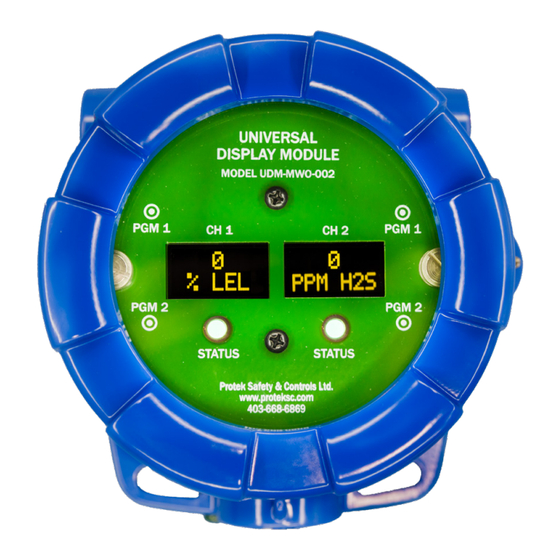
UNIVERSAL DISPLAY MODULE
MULTI-WIRING OPTION
MODEL UDM-MWO-00X-A / UDM-MWO-00X-AR
UDM-MWO-002-A
Operator 's Installation and Instruction Manual
Protek Safety & Controls Ltd.
#10, 1715 – 27th Ave NE
Calgary, AB T2E 7E1
Ph.403-668-6869 / Fax 403-668-6865
www.proteksc.com
July 1, 2024 • Document # 1002 • Revision 0
Advertisement
Table of Contents
Troubleshooting

Related Manuals for Protek UDM-MWO-00-A Series


Summary of Contents for Protek UDM-MWO-00-A Series
- Page 1 UNIVERSAL DISPLAY MODULE MULTI-WIRING OPTION MODEL UDM-MWO-00X-A / UDM-MWO-00X-AR UDM-MWO-002-A Operator ’s Installation and Instruction Manual Protek Safety & Controls Ltd. #10, 1715 – 27th Ave NE Calgary, AB T2E 7E1 Ph.403-668-6869 / Fax 403-668-6865 www.proteksc.com July 1, 2024 • Document # 1002 • Revision 0...
-
Page 3: Table Of Contents
Universal Display Module (MWO Version) Table of Contents 1. Introduction.................... 1 Features....................1 Compatible Gas Detectors..............1 2. Safety Guidelines for Safe Use.............2 3. Installation....................3 Mounting....................3 Field Wiring..................3 4. Startup / Configuration...............8 Startup......................8 Operator Interface....................8 Magnetic Programming Tool.................9 5. - Page 4 Universal Display Module (MWO Version) List of Figures Figure 1: Mounting details..............3 Figure 2: UDM-MWO-00X-A Wiring Diagram (2 & 3-Wire Configurations) 4-20mA Output ONLY Model......4 Figure 3: UDM-MWO-00X-AR Wiring Diagram (2 & 3-Wire Configurations) 4-20mA Output ONLY Model......5 Figure 4: UDM-MWO-00X-A Wiring Diagram (4 & 5-Wire Configurations) 4-20mA Output ONLY Model......6 Figure 5: UDM-MWO-00X-AR Wiring Diagram (4 &...
-
Page 5: Introduction
Universal Display Module (MWO Version) Introduction Features The Universal Display Module Multi Wiring Option (UDM-MWO) is a single or dual channel remote display module designed to achieve remote sensor separation for up to two gas detectors. The UDM-MWO is provided in an epoxy painted explosion-proof enclosure with a viewing window. -
Page 6: Safety Guidelines For Safe Use
Universal Display Module (MWO Version) Below is a list of compatible gas detectors at the time of this manual release for 2-wire or 3-wire sensor separation applications. Sensor Electronics Millenium Series (3-Wire Only) Sensor Electronics Millenium Hawk Series (3-Wire Only) Sensor Electronics SEC3000 Toxic Series (2-Wire or 3-Wire) Sensor Electronics SEC3000 O2 Detector (2-Wire or 3- Wire) Additional parameters may be found by accessing each detector directly depending on... -
Page 7: Installation
Universal Display Module (MWO Version) Installation Mounting The UDM-MWO series can be installed as a wall mount using the mounting tabs of the explosion-proof junction box. Once mounting of the enclosure is complete, the UDM- MWO PCB can be oriented on the square pattern stand-offs to ensure the OLED display is horizontal for viewing. -
Page 8: Figure 2: Udm-Mwo-00X-A Wiring Diagram
Universal Display Module (MWO Version) Figure 2: UDM-MWO-00X-A Wiring Diagram (2 & 3-Wire Configurations) 4-20mA Output ONLY Model UDM-MWO-00X Manual Page | 4... -
Page 9: Figure 3: Udm-Mwo-00X-Ar Wiring Diagram
Universal Display Module (MWO Version) Figure 3: UDM-MWO-00X-AR Wiring Diagram (2 & 3-Wire Configurations) 4-20mA & Relay Output Model UDM-MWO-00X Manual Page | 5... -
Page 10: Figure 4: Udm-Mwo-00X-A Wiring Diagram (4 & 5-Wire Configurations) 4-20Ma Output Only Model
Universal Display Module (MWO Version) GND GRN/YEL B - Wht A + Blu mA Grn - Blk + Red Figure 4: UDM-MWO-00X-A Wiring Diagram (4 & 5-Wire Configurations) 4-20mA Output ONLY Model UDM-MWO-00X Manual Page | 6... -
Page 11: Figure 5: Udm-Mwo-00X-Ar Wiring Diagram
Universal Display Module (MWO Version) GND GRN/YEL B - Wht A + Blu mA Grn - Blk + Red Figure 5: UDM-MWO-00X-AR Wiring Diagram (4 & 5-Wire Configurations) 4-20mA & Relay Output Model UDM-MWO-00X Manual Page | 7... -
Page 12: Startup / Configuration
Universal Display Module (MWO Version) Startup / Configuration Startup On power-up of the UDM-MWO, it will search for connected detectors. The UDM- MWO can operate with multiple detector models, so the search may take a few minutes to find the connected detector. If it finds a detector connected it will upload the detector and parameters to the UDM-MWO and display the model connected along with the concentration and gas type (i.e. -
Page 13: Magnetic Programming Tool
Universal Display Module (MWO Version) Magnetic Programming Tool The magnetic programming tool is used to operate the magnetic switches. To activate the magnetic switch, move the magnet over the circle near each PGM marking on the faceplate. The arrow on the display will indicate which switch is being activated. Figure 6: Programming Magnet Operational Modes The UDM-MWO has a number of different operating modes such as Normal Operation,... -
Page 14: Settings / Program Mode
Universal Display Module (MWO Version) Settings / Program Mode Settings / Program mode allow you can access existing settings or information about the connected sensor, plus change some setting to suit your application or installation. Some of the information available will depend on the sensor that is connected to the UDM-MWO. -
Page 15: View Alarm Settings Menu
Universal Display Module (MWO Version) Sensor Electronics Millenium Series Detectors Display: Sensor Range Autospan Level Gas Curve Model Type Sensor Temperature Note: Sensor Diagnostics (varies by sensor type) Sensor Electronics 3000 Series Detectors Display: Sensor Range Autospan Level Model Type Sensor Temperature Note: Sensor Diagnostics (varies by sensor type) 5.3.2... -
Page 16: Set Autospan Level Menu
Universal Display Module (MWO Version) 5.3.3 Set Autospan Level Menu “Set Autospan Level” is used to set the span gas concentration level that is being used to calibrate the sensor. This adjustable level is dependant on the detector attached. Refer to the applicable detector manual. - Page 17 Universal Display Module (MWO Version) When the “View Alarm Settings” text scrolls, hold the magnet over PGM2 and as soon as the arrow prompt appears, remove the magnet away. Continue this procedure until you reach the “Display ON/OFF” menu. When you reach the menu and the “Display ON/OFF” text scrolls, hold the magnet over PGM2.
-
Page 18: Change Low Alarm Settings Menu
Universal Display Module (MWO Version) 5.3.5 Change Low Alarm Settings Menu “Change Low Alarm Settings” is used to set the optional Low Alarm Relay settings and plus set the setpoint at which the faceplate LED changes to red to notify that gas is being detected by the sensor. - Page 19 Universal Display Module (MWO Version) When the “View Sensor Status” text scrolls, hold the magnet over PGM2 and as soon as the arrow prompt appears, remove the magnet away. When the “View Alarm Settings” text scrolls, hold the magnet over PGM2 and as soon as the arrow prompt appears, remove the magnet away.
-
Page 20: Turning The Aux Ma Output On & Off
Universal Display Module (MWO Version) 5.3.7 Turning the Aux mA Output ON & OFF The Aux mA output(s) are available for use when the UDM-MWO is connected to detectors other than combustible LEL, performance certified detectors such as the Millennium LEL, the FP700, or the IR700 LEL detectors. If the feature is available, based on the connected sensor type, it will be defaulted to OFF and the user must turn on the Aux mA output ON from the “Aux mA On/Off”... -
Page 21: Span Calibration
Universal Display Module (MWO Version) To access the Zero Calibration menu: Hold the magnet over PGM1, of the channel you want to access. When the arrow prompt appears hold the magnet continuously for 3 seconds, “PGM1 = Zero PGM2 = Span” text will scroll. Hold the magnet on PGM1 and when the arrow appears, continue to hold for 3 seconds until the zero calibration is started and “Setting Zero...”... -
Page 22: Figure 7: Detcon 700 & Udm-Mwo 3-Wire Programming Flowchart
Universal Display Module (MWO Version) UDM-MWO-00X Manual Page | 18... - Page 23 Universal Display Module (MWO Version) UDM-MWO-00X Manual Page | 19...
-
Page 24: Figure 8: Sec 3000 & Udm-Mwo 3-Wire Programming Flowchart
Universal Display Module (MWO Version) UDM-MWO-00X Manual Page | 20... - Page 25 Universal Display Module (MWO Version) UDM-MWO-00X Manual Page | 21...
-
Page 26: Figure 9: Sec Millenium & Udm-Mwo 3-Wire Programming Flowchart
Universal Display Module (MWO Version) UDM-MWO-00X Manual Page | 22... - Page 27 Universal Display Module (MWO Version) UDM-MWO-00X Manual Page | 23...
-
Page 28: Service Menu
Universal Display Module (MWO Version) Service Menu The “Service Menu” allows the user access to some diagnostic menus to help trouble- shoot field and operational issues. It is made up of the following sub menus: View Comm Errors Calibrate mA Output Restore Sernsor Defaults View Event Logs Erase Event Logs... - Page 29 Universal Display Module (MWO Version) 5.5.2 Calibrate mA Output This sub menu allows the user to slightly adjust the 4mA & 20mA output values shown at the PLC, RTU or DCS, etc. It is only applicable for the Aux mA output(s) when they are available (depends on the sensor connected).
- Page 30 Universal Display Module (MWO Version) Once the decision is made, hold the magnet on PGM2 to save. If no selection is made the menu will time out return to the “Service Menu” and then to normal operation. If “No Restore” was selected, the display will say, “Defaults Not Restored”...
- Page 31 Universal Display Module (MWO Version) 5.5.5 Erase Event Logs This menu allows the user to erase the event log. To access the “Erase Event Logs” from the “Service Menu”, Hold the magnet over PGM2. When the arrow prompt appears hold the magnet continuously for 3 seconds, “View Comm Errors”...
-
Page 32: Figure 10: Service Menu Programming Flowchart
Universal Display Module (MWO Version) UDM-MWO-00X Manual Page | 28... - Page 33 Universal Display Module (MWO Version) UDM-MWO-00X Manual Page | 29...
-
Page 34: Maintenance And Service Personnel Activities
Universal Display Module (MWO Version) Maintenance and Service Personnel Activities • Service and maintenance activities should be completed according to individual manufacturer specification and should be performed by trained individuals. Any other required service or maintenance related activity shall only be performed by a Factory-Certified technician. - Page 35 Universal Display Module (MWO Version) 7.2.2 “WAIT” continuously scrolling on the display: The 4-20mA output is not connected so the detector cannot complete its startup sequence. Check the 4-20mA loop and ensure you are getting the correct 4-20mA output signal at the PLC or DCS, etc. If the wiring is connected properly but there is no 4-20mA signal being measured at the PLC or DCS, continue with the following steps: •...
-
Page 36: Figure 11: Detcon Sensor Specific Troubleshooting Error Codes Table
Universal Display Module (MWO Version) Figure 11: Detcon Sensor Specific Troubleshooting Error Codes Table Event Log Fault Codes – Detcon Sensors Fault Fault Name Description Action Number Unit has not been span calibrated for 180 Day Cal Reminder Complete a span calibration and recycle power after it is complete. more than 180 days Check Temperature to ensure it is within the detector operating range. -
Page 37: Figure 12: Sensor Electronics Corp Sensor Specific
Universal Display Module (MWO Version) Figure 12: Sensor Electronics Corp Sensor Specific Troubleshooting Error Codes Table Event Log Fault Codes – SEC Sensors Fault Fault Name Description Action Number EEPROM does not have correct Call for additional troubleshooting EEPROM Header Byte header byte stored Checksum byte from EEPROM does EEPROM Checksum... -
Page 38: Customer Support And Service Policy
For on-line technical service, have the model number, part number, and serial number of product(s) in question available. All Sales requests (including spare parts purchase) should be sent to Protek’s Safety & Controls Ltd. by calling 403-668-6869 or emailing sales@proteksc.com. -
Page 39: Specifications
Universal Display Module (MWO Version) Specifications Inputs Sensor Electronics Millenium Series Detectors Sensor Electronics 3000 Series Detectors Detcon Model 700 Gas Detectors (except DM-700-O2) *Detector Models to be verified for functionality at time of quote Input Voltage 10.5-30 VDC (Determined by voltage of attached detectors) Power Consumption (excluding attached gas sensors) <0.5 Watts at 24 VDC (normal) (excluding attached gas sensors) Operating Temperature... -
Page 40: Revision Log
Universal Display Module (MWO Version) Revision Log Revision Date Changes made Approval 08/14/24 Initial Release UDM-MWO-00X Manual Page | 36...
Need help?
Do you have a question about the UDM-MWO-00-A Series and is the answer not in the manual?
Questions and answers