Table of Contents
Advertisement
Quick Links
Advertisement
Table of Contents

Related Manuals for Cisco Catalyst IE3100 Series


Summary of Contents for Cisco Catalyst IE3100 Series
- Page 1 Cisco Catalyst IE3100 Rugged Series Switches Hardware Installation Guide First Published: 2023-03-22 Last Modified: 2023-03-22 Americas Headquarters Cisco Systems, Inc. 170 West Tasman Drive San Jose, CA 95134-1706 http://www.cisco.com Tel: 408 526-4000 800 553-NETS (6387) Fax: 408 527-0883...
- Page 2 © 2023 Cisco Systems, Inc. All rights reserved.
-
Page 3: Introduction
• Connect the equipment into an outlet on a circuit different from that to which the receiver is connected. • Consult the dealer or an experienced radio/TV technician for help. Modifications to this product not authorized by Cisco could void the FCC approval and negate your authority to operate the product. -
Page 4: Communications, Services, And Additional Information
Cisco and the Cisco logo are trademarks or registered trademarks of Cisco and/or its affiliates in the U.S. and other countries. To view a list of Cisco trademarks, go to this URL: https://www.cisco.com/c/en/us/about/... -
Page 5: Bias Free Language
Cisco Catalyst IE3100 Rugged Series Switches Hardware Installation Guide... -
Page 6: Table Of Contents
Port Status LEDs Management Ports Power Connectors System LED Alarms Express Setup Button SD Card Connector Rear Panel Management Options C H A P T E R 2 Switch Installation Preparing for Installation Cisco Catalyst IE3100 Rugged Series Switches Hardware Installation Guide... - Page 7 Attach the Alarm Connector to the Switch Connecting Destination Ports Connect to 10/100/1000 Ports Installing and Removing SFP Modules Connecting to SFP Modules Connect to a Dual-Purpose Port Verifying the Switch Operation What to Do Next Cisco Catalyst IE3100 Rugged Series Switches Hardware Installation Guide...
- Page 8 Complete the Setup Program C H A P T E R 6 Hazardous Location Installation Information Cisco Catalyst IE3100 Rugged Series Switches in Hazardous Locations Hazardous Area Installation Warnings North American Hazardous Location Approval EMC Environmental Conditions for Products Installed in the European Union Hazardous Locations Standards—Normes applicables aux zones dangereuses...
- Page 9 Link Status 10/100/1000 Port Connections SFP Module Interface Settings Ping End Device Spanning Tree Loops Switch Performance Speed, Duplex, and Autonegotiation Reset the Switch Recovering Passwords Finding the Switch Serial Number Cisco Catalyst IE3100 Rugged Series Switches Hardware Installation Guide...
- Page 10 Contents Cisco Catalyst IE3100 Rugged Series Switches Hardware Installation Guide...
-
Page 11: Cisco Catalyst Ie3100 Rugged Series Switches
Cisco Catalyst IE3100 Rugged Series Switches are the next-generation of Layer 2 Catalyst Industrial Switches in Cisco’s IoT DIN rail switching portfolio. The switches are the successor to Cisco Industrial Ethernet 2000 Series Switches but feature Cisco IOS XE software. -
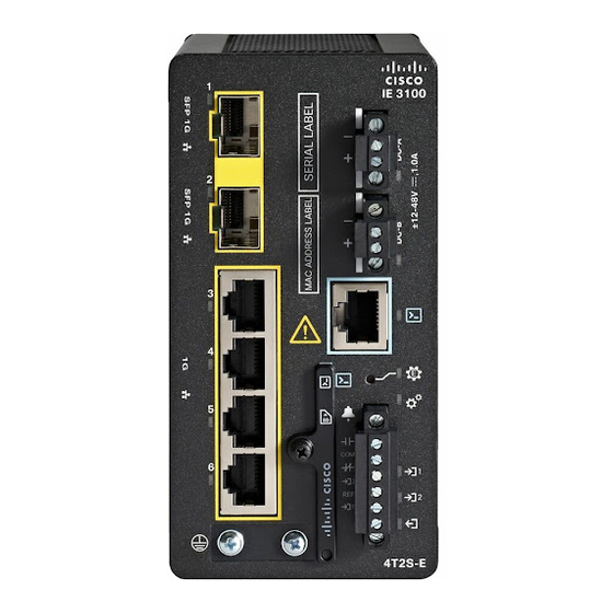
Page 12: Front Panel
• One alarm output • Dual power connectors • A micro-USB port Front Panel This section provides an overview of ports, connectors, and LEDs on front of Cisco Catalyst IE3100 Rugged Series Switches. Cisco Catalyst IE3100 Rugged Series Switches Hardware Installation Guide... - Page 13 Cisco Catalyst IE3100 Rugged Series Switches Front Panel Note This section uses the Cisco Catalyst IE-3105-18T2C-E as an example. Other switches in the series may not have all the same features. See Cisco Catalyst IE3100 Rugged Series Swtiches, on page 1 in this guide for details of each switch model's features.
-
Page 14: Switch Ports
Management console LED Switch Ports Uplink Ports This section describes the uplink ports on Cisco Catalyst IE3100 Rugged Series Switches. The ports vary depending on the switch model. 1000BASE-T/1000BASE-X Dual-Media Ports Dual-media ports include SFP and copper uplink ports. The SFP ports support 1-Gb and 100-Mb modules. -
Page 15: Downlink Ports
SFP Module Cables, on page Downlink Ports All Cisco Catalyst IE3100 Rugged Series Switches have gigabit 1000BASE-T ports that support 1000BASE-T, 100BASE-TX, and 10BASE-T with autonegotiation, auto-MDIX, and cable diagnostics on an RJ-45 connector. The number of downlink ports varies depending on the switch model. See... -
Page 16: Management Ports
USB console is not plugged in. To use the USB-micro console port, you must install the Cisco Windows USB device driver on the device that is connected to the USB-micro console port and that is running Microsoft Windows. -
Page 17: System Led
System is receiving power but is not functioning properly. Alarms You connect the alarm signals to the Cisco Catalyst IE3100 Rugged Series Switch through the alarm connector. The switch has two dry-contact alarm inputs and one dry-contact Form-C relay alarm output. -
Page 18: Express Setup Button
The Cisco Catalyst IE3100 Rugged Series Switch front panel has an Express Setup button and a setup LED. The button is recessed to prevent accidental activation; you need a paper clip or similar object to press it. You trigger different Express Setup features by varying the amount of time that you press the button. -
Page 19: Sd Card Connector
You can also use the SD card to copy files on and off the system. The connector is on the front of the switch, behind a cover that protects the SD card and holds it in place. The cover also protects the USB console port. Cisco Catalyst IE3100 Rugged Series Switches Hardware Installation Guide... -
Page 20: Rear Panel
For more information, see the Web UI online help. • Cisco IOS XE CLI The switch CLI is based on Cisco IOS XE software and is enhanced to support desktop-switching features. You can fully configure and monitor the switch. You can access the CLI either by connecting your management station directly to the switch management port, or a console port, or by using Telnet from a remote management station. - Page 21 Cisco Catalyst IE3100 Rugged Series Switches Management Options configuration guide on Cisco.com and the documentation that came with your SNMP application for more information. • Common Industrial Protocol The Common Industrial Protocol (CIP) management objects are supported. Cisco Catalyst IE3100 Rugged Series Switches can be managed by CIP-based management tools, allowing the user to manage an entire industrial automation system with one tool.
- Page 22 Cisco Catalyst IE3100 Rugged Series Switches Management Options Cisco Catalyst IE3100 Rugged Series Switches Hardware Installation Guide...
-
Page 23: Switch Installation
What to Do Next, on page 61 Preparing for Installation Warnings Be aware of the following warnings for installing Cisco Catalyst IE3100 Rugged Series Switches. These warnings are translated into several languages in the Regulatory Compliance and Safety Information for this switch. - Page 24 Statement 1028 Avertissement : Il se peut que cet appareil ait plus d’une connexion de bloc d’alimentation. Pour mettre l’appareil hors tension, vous devez débrancher toutes les connexions. Énoncé 1028 Cisco Catalyst IE3100 Rugged Series Switches Hardware Installation Guide...
- Page 25 Installation of the equipment must comply with local and national electrical codes. Statement 1074 Avertissement : Installez l’équipement en respectant les réglementations locales et nationales en matière de câblage. Énoncé 1074 Cisco Catalyst IE3100 Rugged Series Switches Hardware Installation Guide...
-
Page 26: Installation Guidelines
If you are responsible for the application of safety-related programmable electronic systems (PES), you must be aware of the safety requirements in the application of the system and be trained in using the system. Cisco Catalyst IE3100 Rugged Series Switches Hardware Installation Guide... - Page 27 Une protection contre les décharges électrostatiques appropriée est nécessaire chaque fois que vous manipulez de l’équipement Cisco. Le personnel responsable de l’installation et de la maintenance doit être correctement protégé à l’aide de bracelets de mise à la terre afin d’éliminer tout risque de décharge électrostatique sur le commutateur.
-
Page 28: Verifying The Package Contents
Some components are optional, depending on your order. Note Verify that you have received these items. If any item is missing or damaged, contact your Cisco representative or reseller for instructions. Install or Remove the Flash Memory Card (Optional) Software and firmware are stored on the internal flash memory in Cisco Catalyst IE3100 Rugged Series Switches. - Page 29 Close the guard door and fasten the captive screw using a Phillips screwdriver to keep the door in place. • a. To remove the card, push it in until it releases for it to pop out. Cisco Catalyst IE3100 Rugged Series Switches Hardware Installation Guide...
-
Page 30: Connecting To A Console Port
Connect the RJ-45-to-DB-9 adapter cable to the 9-pin serial port on the PC. Step 2 Connect the other end of the cable to the switch console port. The following illustration shows the connections in Step 1 and Step 2. Cisco Catalyst IE3100 Rugged Series Switches Hardware Installation Guide... - Page 31 Configure the baud rate and character format of the PC or terminal to match the console port characteristics: • 9600 baud • 8 data bits • 1 stop bit • No parity Cisco Catalyst IE3100 Rugged Series Switches Hardware Installation Guide...
-
Page 32: Connect To The Usb Micro-Type B Console Port
Use a Phillips screwdriver to loosen the captive screw on the cover of the USB micro type B console port, as shown in the following illustration. The USB port shares its cover with the SD card connector. Cisco Catalyst IE3100 Rugged Series Switches Hardware Installation Guide... - Page 33 Connect a USB cable to the PC USB port. Step 4 Connect the other end of the cable to the switch micro-B (5-pin connector) USB-micro console port, as shown in the following illustration. Cisco Catalyst IE3100 Rugged Series Switches Hardware Installation Guide...
- Page 34 Choose Start > Control Panel > System>. b) Click the Hardware tab and choose Cisco Device Manager, and then expand the Ports section. The assigned COM port appears in parentheses at the end of the line with this entry: Cisco USB System Management Console.
-
Page 35: Connecting To Power
• A number-2 Phillips screwdriver. • A flat-blade screwdriver. Supported Power Supplies Cisco is constantly updating the IoT Power Supply portfolio. Please refer to the Cisco Industrial Din-Rail Power Supplies Data Sheet for a comprehensive list of supported power supplies and their capabilities. -
Page 36: Installing The Power Converter
The ground lug is not supplied with the switch. You can use one of the following options: • Single ring terminal • Two single ring terminals Before you begin Read and understand the following warnings and cautions: Cisco Catalyst IE3100 Rugged Series Switches Hardware Installation Guide... - Page 37 Insert the ground wire into the ring terminal lug, and using a crimping tool, crimp the terminal to the wire, as shown in the following illustration. If two ring terminals are being used, repeat this action for a second ring terminal. Cisco Catalyst IE3100 Rugged Series Switches Hardware Installation Guide...
- Page 38 Use a ratcheting torque screwdriver to tighten the ground screws and ring terminal to the switch front panel to 3.5 in-lb (0.4 N-m). Note Do not exceed 3.5 in-lb (0.4 N-m) of torque. Figure 12: Installing the Ground-Lug Screw (Single Ring Terminal) Ground cable Cisco Catalyst IE3100 Rugged Series Switches Hardware Installation Guide...
-
Page 39: Connecting The Power Converter To An Ac Power Source
Power-cord wiring color codes also vary by country. You must have a qualified electrician elect, prepare, and install the appropriate power cord to the power supply. Use copper conductors, rated at a minimum temperature of 86°F (30°C) above the operating ambient temperature. Cisco Catalyst IE3100 Rugged Series Switches Hardware Installation Guide... -
Page 40: Connect The Ac Power Source To The Power Converter
Figure 14: Connecting AC Power Ground AC line AC neutral Step 3 Tighten the ground wire terminal block screw. Torque to 8 in.-lb, not to exceed 10 in-lb. Note Cisco Catalyst IE3100 Rugged Series Switches Hardware Installation Guide... -
Page 41: Connect The Power Converter To A Dc Power Source
Insert the other end of the exposed ground wire lead into the earth-ground wire connection on the power converter terminal block. Ensure that only wire with insulation extends from the connection, as shown by item 1 in the following illustration. Cisco Catalyst IE3100 Rugged Series Switches Hardware Installation Guide... -
Page 42: Wire The Dc Power Source
Ensure that each pole has a current-limiting-type fuse that is rated to at least 600 VAC/DC (such as the KLKD Midget fuse). Wire the DC Power Source Complete the following steps to wire the switch to a DC power source: Cisco Catalyst IE3100 Rugged Series Switches Hardware Installation Guide... - Page 43 Before performing any of the following procedures, ensure that power is removed from the DC circuit. Statement 1003 Avertissement : Avant d’exécuter une de ces procédures, assurez-vous que l’alimentation du circuit CC est coupée. Énoncé 1003 Cisco Catalyst IE3100 Rugged Series Switches Hardware Installation Guide...
- Page 44 Figure 17: Stripping the Power Connection Wire 0.25 in. (6.3 mm) ± 0.02 in. (0.5 mm) Step 5 Remove the two captive screws that attach the power connector to the switch, and remove the power connector. Cisco Catalyst IE3100 Rugged Series Switches Hardware Installation Guide...
- Page 45 Ensure that you cannot see any wire lead. Only wire with insulation should extend from the connector. Figure 19: Inserting Wires in the Power Connector Power source positive connection Power source return connection Cisco Catalyst IE3100 Rugged Series Switches Hardware Installation Guide...
- Page 46 Power source A return connection Power source B return connection For a –48 VDC power source, this table describes the wiring connections. Power source A return connection Power source B return connection Cisco Catalyst IE3100 Rugged Series Switches Hardware Installation Guide...
-
Page 47: Attach The Power Connectors To The Switch
Assurez-vous que le commutateur et tous les autres circuits ne sont pas sous tension. Avant de commencer, assurez-vous qu’il est impossible de brancher accidentellement l’alimentation électrique et vérifiez que la zone n’est pas dangereuse. Énoncé 1058 Cisco Catalyst IE3100 Rugged Series Switches Hardware Installation Guide... - Page 48 When you are installing the switch, secure the wires coming from the power connector so that they cannot be disturbed by casual contact. For example, use tie wraps to secure the wires to the rack. Cisco Catalyst IE3100 Rugged Series Switches Hardware Installation Guide...
-
Page 49: Apply Power To The Power Converter
After the power is connected, the switch automatically begins the power-on self-test (POST), a series of tests that verifies that the switch functions properly. Cisco Catalyst IE3100 Rugged Series Switches Hardware Installation Guide... -
Page 50: Installing The Switch
This section describes how to install or remove the switch. Install the Switch on a DIN Rail To install the Cisco Catalyst IE3100 Rugged Series Switch, complete the following steps. Note In order to prevent excessive side to side movement of the unit, it is advised to install DIN rail stop plates such as Mouser part Numbers 653-PFP-M, 651-1201662 or 845-CA402. - Page 51 Install the Switch on a DIN Rail Step 2 Rotate the switch so that the top hook of the DIN clip clamps to the top section of DIN rail. Refer to the following figures. Cisco Catalyst IE3100 Rugged Series Switches Hardware Installation Guide...
-
Page 52: Remove The Switch From A Din Rail
For instructions on how to remove the switch from a DIN rail, see Removing the Switch from a DIN Rail, Remove the Switch from a DIN Rail To remove the Cisco Catalyst IE3100 Rugged Series Switch with the bracket from the DIN rail, complete the following steps. - Page 53 Grasp the upper part of the switch and rotate it away from the DIN rail. Refer to the following figure. Step 3 Lower the switch away from the DIN rail and remove it. Refer to the following figure. Cisco Catalyst IE3100 Rugged Series Switches Hardware Installation Guide...
-
Page 54: Connecting Alarm Circuits
The following table shows the labels for the alarm connector that are on the switch panel. Table 9: Alarm Connector Labels (Top to Bottom) Label Connection Alarm Output Normally Open (NO) connection Cisco Catalyst IE3100 Rugged Series Switches Hardware Installation Guide... - Page 55 Read the following content before wiring the external alarms. Step 1 Remove the captive screws that hold the alarm connector on the switch, and remove the connector from the switch chassis. Cisco Catalyst IE3100 Rugged Series Switches Hardware Installation Guide...
- Page 56 Insert the exposed wires for the external alarm device into the connections based on an alarm input or output circuit setup. Refer to the table earlier in this section. For example, to wire an alarm input circuit, complete the IN1 and REF connections. Cisco Catalyst IE3100 Rugged Series Switches Hardware Installation Guide...
- Page 57 NO and COM connections complete the circuit. Figure 28: Completed Connections for Three External Alarm Devices on the Alarm Connector IN1 wired connection COM wired connection Cisco Catalyst IE3100 Rugged Series Switches Hardware Installation Guide...
-
Page 58: Attach The Alarm Connector To The Switch
électrique et vérifiez que la zone n’est pas dangereuse. Énoncé 1058 Step 1 Insert the alarm connector into the receptacle on the switch front pane, as shown in the following illustration. Cisco Catalyst IE3100 Rugged Series Switches Hardware Installation Guide... -
Page 59: Connecting Destination Ports
If the attached ports do not support autonegotiation, you can explicitly set the speed and duplex parameters. Connecting devices that do not autonegotiate or that have their speed and duplex parameters that are manually set can reduce performance or result in no linkage. Cisco Catalyst IE3100 Rugged Series Switches Hardware Installation Guide... - Page 60 To connect to 10BASE-T, 100BASE-TX, or 1000BASE-T devices, complete the following steps: Step 1 When connecting to workstations, servers, routers, and Cisco IP phones, connect a straight-through cable to an RJ-45 connector on the front panel, as shown in the following illustration.
-
Page 61: Installing And Removing Sfp Modules
These sections describe how to install and remove SFP modules. SFP modules are inserted into SFP module slots on the front of the switch. Field-replaceable SFP modules provide the uplink interfaces, send (TX) and receive (RX). Cisco Catalyst IE3100 Rugged Series Switches Hardware Installation Guide... - Page 62 SFP module. Disconnect all cables before removing or installing an SFP module. Removing and installing an SFP module can shorten its useful life. Do not remove and insert SFP modules more often than is absolutely necessary. Cisco Catalyst IE3100 Rugged Series Switches Hardware Installation Guide...
- Page 63 You can insert the SFP module into either of the two ports outlined in red in the preceding illustration. Step 5 Remove the dust plugs from the SFP module optical ports and store them for later use. Cisco Catalyst IE3100 Rugged Series Switches Hardware Installation Guide...
- Page 64 CAT5 cabling for the SFP transceiver port. When connecting to a 1000BASE-T-compatible switch or repeater, use four twisted-pair, crossover CAT5 cabling. Complete the following steps to install a 1000BASE-T SFP transceiver. Cisco Catalyst IE3100 Rugged Series Switches Hardware Installation Guide...
- Page 65 Position the SFP transceiver in front of the port socket opening. Note Different Cisco devices have different SFP transceiver socket configurations. Your Cisco device might require that the SFP transceiver be installed with the bale-clasp either in a latch-up or a latch-down orientation.
-
Page 66: Connecting To Sfp Modules
This section describes how to connect to a fiber-optic or copper SFP port. Warning Class 1 laser product. Statement 1008 Avertissement : Produit laser de classe 1. Énoncé 1008 Note The following warning applies only to installation in hazardous locations. Cisco Catalyst IE3100 Rugged Series Switches Hardware Installation Guide... - Page 67 Remove the rubber plugs from the module port and fiber-optic cable, and store them for future use. Step 2 Insert one end of the fiber-optic cable into the SFP module port, as shown in the following illustration. Cisco Catalyst IE3100 Rugged Series Switches Hardware Installation Guide...
- Page 68 Complete the following steps to connect a CAT5 cable to a 1000BASE-T SFP module: Step 1 Insert a cable into the RJ-45 connector: If you are connecting to... Then insert... Servers, workstations, and routers A four twisted-pair, straight-through cable Cisco Catalyst IE3100 Rugged Series Switches Hardware Installation Guide...
-
Page 69: Connect To A Dual-Purpose Port
For more information about dual-purpose ports, see Power Connectors, on page 6 in this guide. Warning Class 1 laser product. Statement 1008 Avertissement : Produit laser de classe 1. Énoncé 1008 Cisco Catalyst IE3100 Rugged Series Switches Hardware Installation Guide... - Page 70 Connect an RJ-45 connector to the 10/100/1000 port, or install an SFP module into the SFP module slot, and connect a cable to the SFP module port. The following illustration shows the dual-port connection. Figure 36: Connecting to a Dual-purpose Port Cisco Catalyst IE3100 Rugged Series Switches Hardware Installation Guide...
-
Page 71: Verifying The Switch Operation
• Use the CLI to configure the switch as an individual switch from the console. • Start an SNMP application. • Start the Common Industrial Protocol (CIP) management tool. You can manage an entire industrial automation system with the CIP-based tools. Cisco Catalyst IE3100 Rugged Series Switches Hardware Installation Guide... - Page 72 Switch Installation What to Do Next Cisco Catalyst IE3100 Rugged Series Switches Hardware Installation Guide...
-
Page 73: Cables And Connectors
The 10/100/1000 Ethernet ports on the switches use RJ-45 connectors. Figure 37: 10/100/1000 Port Pinouts SFP Module Connectors The following illustration shows a Lucent Connector (LC) style, fiber-optic cable connector. Figure 38: Fiber-Optic SFP Module LC Connector Cisco Catalyst IE3100 Rugged Series Switches Hardware Installation Guide... -
Page 74: Console Port
(unlocked) position Bale-clasp latching mechanism in the closed Console Port The switch has two console ports: a USB micro-Type B port and an RJ-45 console port, both on the front panel. Cisco Catalyst IE3100 Rugged Series Switches Hardware Installation Guide... - Page 75 PC. You must provide a RJ-45-to-DB-25 female DTE adapter if you want to connect the switch console port to a terminal. You can order a kit (part number ACS-DSBUASYN=) containing that adapter. Cisco Catalyst IE3100 Rugged Series Switches Hardware Installation Guide...
-
Page 76: Alarm Port
Each port must match the wave-length specifications on each end of the cable, and for reliable communications, the cable must not exceed the allowable length. See the Cisco Catalyst IE3100 Rugged Series Data Sheet on cisco.com for detailed cabling information. -
Page 77: Sfp Module Patch Cable
Figure 42: SFP Module Patch Cable Cable Pinouts This section contains information about cable pinouts for different cables that are used with Cisco Catalyst IE3100 Rugged Series Switches. Figure 43: Two Twisted-Pair Straight-Through Cable Schematic for 10/100 Ports Figure 44: Two Twisted-Pair Crossover Cable Schematic for 10/100 Ports... -
Page 78: Console Port Adapter Pinouts
The following table lists the pinouts for the console port, the RJ-45-to-DB-9 adapter cable, and the console device. Table 11: Console Port Signaling Using a DB-9 Adapter Switch ConsolePort (DTE) RJ-45-to-DB-9Terminal Adapter ConsoleDevice Signal DB-9 Pin Signal Cisco Catalyst IE3100 Rugged Series Switches Hardware Installation Guide... - Page 79 The following table lists the pinouts for the switch console port, RJ-45-to-DB-25 female DTE adapter, and the console device. Table 12: Console Port Signaling Using a DB-25 Adapter Switch Console Port (DTE) RJ-45-to-DB-25Adapter Console Device Signal DB-25 Pin Signal Cisco Catalyst IE3100 Rugged Series Switches Hardware Installation Guide...
- Page 80 Cables and Connectors Console Port Adapter Pinouts Cisco Catalyst IE3100 Rugged Series Switches Hardware Installation Guide...
-
Page 81: Express Setup
• A small paper clip to reach the button. Note Before running Express Setup, disable any pop-up blockers or proxy settings on your browser and any wireless client running on your computer. Cisco Catalyst IE3100 Rugged Series Switches Hardware Installation Guide... -
Page 82: Run Express Setup
• Blinking Express Setup LED: Ready for express setup process Step 6 Insert a paper clip into Express Setup button for 1 to 2 seconds. Step 7 Connect the computer to port Gi1/3. The LED continues to blink. Cisco Catalyst IE3100 Rugged Series Switches Hardware Installation Guide... - Page 83 CIP enabled. If the CIP VLAN is different from the management VLAN, you must specify an IP address for the CIP VLAN. Make sure that the IP address that you assign to the switch is not being used by another device in your network. Cisco Catalyst IE3100 Rugged Series Switches Hardware Installation Guide...
- Page 84 Turn off DC power at the source, disconnect all cables to the switch, and install the switch in your network. Step 15 If you changed the static IP address on your computer, change it to the previously configured static IP address. Cisco Catalyst IE3100 Rugged Series Switches Hardware Installation Guide...
-
Page 85: Switch Configuration With The Cli Setup Program
• Entering the Initial Configuration Information, on page 78 Accessing the CLI Through the Console Port You can enter Cisco IOS commands and parameters through the CLI. Use one of the following methods to access the CLI: • Accessing the CLI through the RJ-45 Console Port, on page 75 •... -
Page 86: Accessing The Cli Through The Usb Micro-Type B Console Port
Connect a USB cable to the PC USB port, and connect the other end of the cable to the switch micro-B USB console port. The port is shown in the following illustration. Cisco Catalyst IE3100 Rugged Series Switches Hardware Installation Guide... - Page 87 Choose Start > Control Panel > Systems. b) Click the Hardware tab and then choose Device Manager. c) Expand Ports. The assigned COM port appears in parenthesis at the end of the line with this entry: Cisco USB System Management Console. Step 3 Start the terminal-emulation program on the PC or the terminal.
-
Page 88: Entering The Initial Configuration Information
At the setup prompt, enter Yes at the prompt, as shown in the following example: Example: Would you like to enter basic management setup? [yes/no]: yes Step 2 Enter the host name, as shown in the following example: Example: Cisco Catalyst IE3100 Rugged Series Switches Hardware Installation Guide... - Page 89 YES unset down down GigabitEthernet1/17 unassigned YES unset down down GigabitEthernet1/18 unassigned YES unset down down GigabitEthernet1/19 unassigned YES unset down down GigabitEthernet1/20 unassigned YES unset down down AppGigabitEthernet1/1 unassigned YES unset Cisco Catalyst IE3100 Rugged Series Switches Hardware Installation Guide...
- Page 90 GigabitEthernet1/5 interface GigabitEthernet1/6 interface GigabitEthernet1/7 interface GigabitEthernet1/8 interface GigabitEthernet1/9 interface GigabitEthernet1/10 interface GigabitEthernet1/11 interface GigabitEthernet1/12 interface GigabitEthernet1/13 interface GigabitEthernet1/14 interface GigabitEthernet1/15 interface GigabitEthernet1/16 interface GigabitEthernet1/17 interface GigabitEthernet1/18 interface GigabitEthernet1/19 interface GigabitEthernet1/20 Cisco Catalyst IE3100 Rugged Series Switches Hardware Installation Guide...
- Page 91 To use the CLI, enter commands at the Switch > prompt through the console port by using a terminal emulation program or through the network by using Telnet. For configuration information, see the switch software configuration guides on cisco.com. Cisco Catalyst IE3100 Rugged Series Switches Hardware Installation Guide...
- Page 92 Switch Configuration with the CLI Setup Program Complete the Setup Program Cisco Catalyst IE3100 Rugged Series Switches Hardware Installation Guide...
-
Page 93: Hazardous Location Installation Information
C H A P T E R Hazardous Location Installation Information • Cisco Catalyst IE3100 Rugged Series Switches in Hazardous Locations, on page 83 • Hazardous Area Installation Warnings, on page 83 • North American Hazardous Location Approval, on page 85 •... - Page 94 This equipment is suitable for use in Class 1, Division 2, Groups A, B, C, D or only in nonhazardous locations. Attention : Cet appareil est destiné à une utilisation dans un environnement de Classe 1, Division 2, Groupes A, B, C, D ou uniquement dans des zones non dangereuses. Cisco Catalyst IE3100 Rugged Series Switches Hardware Installation Guide...
-
Page 95: North American Hazardous Location Approval
Airflow around the switch must be unrestricted. To prevent the switch from overheating, there must be a minimum of 1.0 in. (25.4 mm) around all surfaces of the switch. Contact your Cisco Technical Assistance Center (TAC) if tighter spacings are required. -
Page 96: Emc Environmental Conditions For Products Installed In The European Union
In addition, if equipment is operated in a domestic environment, interference could occur. Hazardous Locations Standards Normes applicables aux zones dangereuses This section provides information about hazardous locations standards for Cisco Catalyst IE3100 Rugged Series Switches. Note The switches must be installed only in a vertical position. - Page 97 DEMKO UL 23 ATEX 2943X UL23UKEX2764X DEMKO UL 23 ATEX 2943X UL23UKEX2764X Class 1, Zone 2, AEx ec nC IIC T4Gc X Classe 1, Zone 2, AEx ec nC IIC T4Gc X Cisco Catalyst IE3100 Rugged Series Switches Hardware Installation Guide...
- Page 98 Hazardous Location Installation Information Hazardous Locations Standards Normes applicables aux zones dangereuses Cisco Catalyst IE3100 Rugged Series Switches Hardware Installation Guide...
-
Page 99: Technical Specifications
The most current technical specifications for the Cisco Catalyst IE3100 Rugged Series Switches can be found in the Cisco Catalyst IE3100 Rugged Series Switch Data Sheet. You can find other specs and detail that are not in the Data Sheet in this section. -
Page 100: Environmental Ranges
Technical Specifications Environmental Ranges Environmental Ranges The following table displays environmental ranges for Cisco Catalyst IE3100 Rugged Series Switches. Table 15: Environmental Ranges Measure Range Operating temperature • Blower-equipped cabinet: –40° C to +75°C (-40° F to 167° F) • Vented cabinet: –40° C to +70° C (-40° F to 158°... -
Page 101: Power Input Ratings
• Use industrial grade SFP modules that are rated for -40C to +85C operation. • For marine installations, you must install the product inside a metal enclosure, preferably IP54 or better. Cisco Catalyst IE3100 Rugged Series Switches Hardware Installation Guide... - Page 102 Technical Specifications Installation Guidelines for Utility, Railway, and Marine Environments Cisco Catalyst IE3100 Rugged Series Switches Hardware Installation Guide...
-
Page 103: Troubleshooting
You can also get statistics from the Web UI, the CLI, or an SNMP workstation. See the software configuration guides for Cisco Catalyst IE3100 Rugged Series Switches or the documentation that came with your SNMP application for details. -
Page 104: Ethernet And Fiber-Optic Cables
• Verify the status of all ports by checking the LEDs. For more information, see information about LEDs in the chapter Cisco Catalyst IE3100 Rugged Series Switches, on page 1 in this guide. • Use the show interfaces privileged EXEC command to see if the port is error-disabled, disabled, or shut down. -
Page 105: Sfp Module
This encoding verifies that the module meets the requirements for the switch. • Inspect the SFP module. Exchange the suspect module with a known good module. • Verify that the module is supported on this platform. (The switch release notes on Cisco.com list the SFP modules that the switch supports.) •... -
Page 106: Reset The Switch
The button is recessed behind a small hole in the faceplate. The Express Setup LED turns green after the switch reboots. Step 2 Press the Express Setup button again for 3 seconds. A switch 10/100 Ethernet port blinks green. Cisco Catalyst IE3100 Rugged Series Switches Hardware Installation Guide... -
Page 107: Recovering Passwords
Finding the Switch Serial Number If you contact Cisco Technical Assistance, you must know the serial number of your switch. You can also use the show version privileged EXEC command to obtain the switch serial number. Also, the Serial Number for the switch is printed on the device label, on the device itself. - Page 108 Troubleshooting Finding the Switch Serial Number Cisco Catalyst IE3100 Rugged Series Switches Hardware Installation Guide...
Need help?
Do you have a question about the Catalyst IE3100 Series and is the answer not in the manual?
Questions and answers