Table of Contents
Advertisement
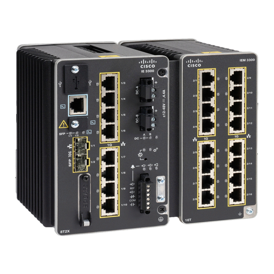
Switch Installation
•
Switch Installation
This chapter describes how to install your switch, verify the boot fast, and connect the switch to other devices.
It also includes information specifically for installations in hazardous environments.
Note
Please refer to the Product Documentation of Compliance for certified installation procedures in Hazardous
Locations.
Read these topics, and perform the procedures in this order:
Preparing for Installation
This section provides information about these topics:
Warnings
These warnings are translated into several languages in the Regulatory Compliance and Safety Information
for this switch.
Warning
Before working on equipment that is connected to power lines, remove jewelry (including rings, necklaces,
and watches). Metal objects will heat up when connected to power and ground and can cause serious burns
or weld the metal object to the terminals. Statement 43
Warning
Do not work on the system or connect or disconnect cables during periods of lightning activity. Statement
1001
Switch Installation, on page 1
Switch Installation
1
Advertisement
Table of Contents


Need help?
Do you have a question about the Catalyst IE 3 00 Series and is the answer not in the manual?
Questions and answers