Table of Contents
Advertisement
Advertisement
Table of Contents

Related Manuals for 3D Systems ProX SLS 6100


Summary of Contents for 3D Systems ProX SLS 6100
- Page 1 ProX® SLS 6100 3D Printer User Guide Original Instructions 3D Systems, Inc.
-
Page 2: Table Of Contents
Safe Material Handling Guidelines . . . . . . . . . . . . . . . . . . . . . . . . . . . . . . . . . . . . . . . . . . . . . . . . . . . . . . . . . . . . . . . . . . . . . . . .14 p/n 76-D020 Rev. A 3D Systems, Inc. - Page 3 Where to Cool Down the Print Cake . . . . . . . . . . . . . . . . . . . . . . . . . . . . . . . . . . . . . . . . . . . . . . . . . . . . . . . . . . . . . . . . . . . . . . .28 p/n 76-D020 Rev. A 3D Systems, Inc.
- Page 4 EC DECLARATION OF CONFORMITY . . . . . . . . . . . . . . . . . . . . . . . . . . . . . . . . . . . . . . . . . . . . . . . . . . . . . . . . . . . . . . . . . . . . . . 42 p/n 76-D020 Rev. A 3D Systems, Inc.
-
Page 5: Introduction
Refer to the following manuals for additional information: 3D Sprint Quick Start Guide This guide takes you through the 3D Sprint SLS workflow for setting up your first print with the new ProX SLS 6100 Material Guides Each material used with the ProX® SLS 6100 system has its own manual which details the part printing and processing procedures specific to that material. -
Page 6: Introduction To The Prox® Sls 6100
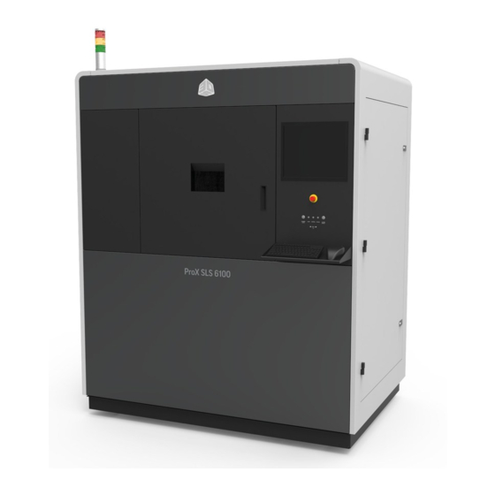
INTRODUCTION TO THE PROX® SLS 6100 The ProX® SLS 6100, the new cutting-edge Selective Laser Sintering (SLS) production 3D printer from 3D Systems, takes SLS toughness, part quality and manufacturing economics to the next level . Designed for smooth integration with your manufacturing workflow, the ProX®... -
Page 7: Auxiliary Sls Equipment
Nitrogen Generator Bead Blaster (Optional) 3D Systems manufactures a High-Performance Nitrogen If you plan to use DuraForm SLS material, 3D Systems Generator — Part Number 104011-02 . The generator is ideal for recommends you install a pneumatic abrasive blast SLS applications . -
Page 8: Prox® Sls 6100 System Components
. USB: There is one standard auxiliary USB port connected to the control PC . It is located under the LED Indicators . p/n 76-D020 Rev. A 3D Systems, Inc. - Page 9 . It is part of a wider system of electronic components (Field-Programmable Gate Arrays, Digital Signal Processors, etc .) which control the hardware of the system . Computer ProX® SLS 6100 Rear View p/n 76-D020 Rev. A 3D Systems, Inc.
-
Page 10: Part Transfer Cart Assembly
System is in service System warning active and/or E-Stop condition Yellow mode message present on touchscreen or normal System Active, not printing, E-Stop condition Green Print job active manual operations possible or normal p/n 76-D020 Rev. A 3D Systems, Inc. -
Page 11: Safety Guidelines & Instructions
Operators are trained to operate the system and perform all the necessary tasks to print a part . • Certified service personnel are those who have completed the 3D Systems service training package and are certified to perform service tasks. Certification may occur at various levels, and servicers should only perform tasks they are authorized and certified to complete. -
Page 12: Safety Symbols And Definitions
CAUTION: Indicates something may happen that could cause loss of data, damage to equipment, or personal injury . CRUSH HAZARD: Injury or death from crushing weight . NOTCHED BELT ENTANGLEMENT: Injury or death from entanglement in notched pulley drive belt . p/n 76-D020 Rev. A 3D Systems, Inc. -
Page 13: First Aid Section - What To Do
• Any other pertinent information Please send this information to 3D Systems within a day of the accident . Electrocution The SLS system contains equipment energized at 208 volts, 3-phase delta . Do not attempt to remove protective panels . There are no user serviceable parts inside . -
Page 14: Sls Equipment Safety Features
. If you suspect a safety interlock device is not working properly, do not operate your SLS equipment . Rather, disconnect power from the equipment and contact 3D Systems Customer Support for assistance . SLS System Response if an Interlock Fails Safety interlock devices mounted on the SLS system sense the hazardous operating conditions below . -
Page 15: Other Active Safety Features
When operating any SLS equipment, keep the following electrical safety points in mind: • Only 3D Systems certified service personnel should operate SLS equipment with access panels or service doors open. • Heed high voltage warning signs and labels . -
Page 16: Laser Safety
(panel or door), you can be exposed to hazardous direct and scattered Class 4 invisible laser radiation which can cause severe burns and eye injury, or start a fire. Model: ProX SLS 6100 Yr. of Manu: Mass (kg): 1200 Electrical: 208 VAC, 3-Phase, 50/60 Hz, 10 kVA Elect. -
Page 17: Material Safety
MATERIAL SAFETY All materials certified by 3D Systems are safe during normal operation. However, you should be aware of the following issues: • Any material, material-like substance, or airborne cloud of material has a remote chance of rapid combustion . -
Page 18: Material Safety Information
Material Handling Precautions During normal operation of the SLS system using 3D Systems’ materials, you are not required to wear a dust mask or special personal protection equipment unless specifically designated. Check the SDS of the material used for the specific precautions you should observe . -
Page 19: Nitrogen/Oxygen Safety
4 – 6 % Coma within 40 seconds; convulsions, respiration ceases, death occurs . a . From Safety Bulletin SB-2 - 1983—”1983 by the Compressed Gas Association, Inc . 1235 Jefferson Davis Highway, Arlington, VA 22202 p/n 76-D020 Rev. A 3D Systems, Inc. -
Page 20: Printing Parts With The Prox® Sls 6100
The ProX® MQC System should be started and filled with material before proceeding. After it has been loaded with material, it will need to transfer the material to the printer . The ProX® MQC System must be in Full cycle mode for material to be sent from the blended bin to the ProX SLS 6100 . Before Material Guide selecting Full or Local cycle mode, the user should verify that the desired blend ratio is selected . -
Page 21: Preparing A Print Job Using 3D Sprint
PREPARING A PRINT JOB USING 3D SPRINT 3D Sprint is 3D Systems’ exclusive software for importing CAD data and preparing it for printing . 3D Sprint can be used either on the ProX 6100 or remotely connected from your workstation or off-line at a stand-alone workstation (Virtual Printer) . The 3D Sprint application contains extensive help with further details pertaining to the operation of the software . -
Page 22: Position Parts In The Virtual Build Volume
You modify scale and offset values in the Scale & Offset Editor dialog As with part placement, see Material Guides for more information about specifics for build, part and scale values. 3D Systems supplies sample build packets which can be used for reference when getting started p/n 76-D020 Rev. -
Page 23: Quality Check (Optional)
Once the print job has finished, the part cake will need to be cooled and transported to the SLS Single Use MQC System for breakout you should refer to your Material Guide for more specific information about cooling times and breakout.. p/n 76-D020 Rev. A 3D Systems, Inc. -
Page 24: Pre/Post Build Checklist
. If the piston or roller is moving when this happens you will need to re-home each of them . NOTE: When ProX SLS 6100 is idle, keep inner and outer doors closed, and all interlocked covers on so that the IR core heater remains on and the IR core is at a stable temperature . -
Page 25: Before Starting The Build
Note: If ProX SLS 6100 is not run for several days, it may take several layers while leveling powder for feed powder to dispense properly . Note2: If Feed Hopper is emptied completely and then re-filled, allow several hours before starting a build so that powder “settles”... -
Page 26: Prox® Sls 6100 System Operations
. Messages are color coded to indicate their type . You can select a message and then right-click to acknowledge it; after you do so, it turns black, whatever its initial color was . See Responding to Messages in Sinter Help for more information on acknowledging messages . p/n 76-D020 Rev. A 3D Systems, Inc. -
Page 27: Restarting A Terminated Build
Otherwise, the system draws new slices on top of old ones . You can toggle this option on or off by selecting it . When checked, the system displays a dark Dark background background in the Build Viewer window . p/n 76-D020 Rev. A 3D Systems, Inc. -
Page 28: Pausing A Build
If you make changes near the current Z, the system may not be able to apply them. If you do not get the message The parameter change has been applied after clicking Apply, try again at a higher Z. (There is no message when the attempt fails .) p/n 76-D020 Rev. A 3D Systems, Inc. -
Page 29: Adding And Deleting Parts And Other Changes
. When a Build Ends At the end of a build, the Sinter application displays a summary of the actual build times such as the example below: p/n 76-D020 Rev. A 3D Systems, Inc. -
Page 30: Manual Operations
. If a button you need to use is dim when it should be enabled, close and reopen the Add Powder Layer dialog box to enable the button . p/n 76-D020 Rev. A 3D Systems, Inc. -
Page 31: The Following Parameters Are Available To Set In The Add Powder Layer Dialog
NOTE: If the IR sensor core temperature is below 77 °C, the offline IR Calibration will wait until 77 °C has been reached, and then an additional 5 minutes for the core to stabilize . p/n 76-D020 Rev. A 3D Systems, Inc. -
Page 32: Removing The Print Cake From The Print Chamber
5 . Remove the Laser Window by turning it counterclockwise ¼-turn and pulling it out of the top of the chamber . Put it in a safe, clean location and clean it before reinstalling it into the print chamber . 6 . Press the red Laser Window Baffle Plug into the top of the chamber (see photo). p/n 76-D020 Rev. A 3D Systems, Inc. - Page 33 14 . Move and align the cart to the print chamber . 15 . Slide the cylinder and tray out of the chamber and onto the cart . 16 . Move the transfer cart to the MQC System . p/n 76-D020 Rev. A 3D Systems, Inc.
-
Page 34: Breaking Out Parts
3D Systems recommends you also purchase a glass bead blaster (pneumatic blast cabinet). A bead blaster makes fine cleaning much easier and faster . See your Facility Guide for recommended third party suppliers . -
Page 35: Maintenance Procedures
Do not perform any procedures that are not covered in this section or that you are not fully trained and qualified to per- form . MAINTENANCE KIT With each ProX SLS 6100, 3D Systems provides a maintenance kit for routine maintenance procedures . Many of the tools you need for these procedures can be found in this kit . PRINT CHAMBER MAINTENANCE Replacing Light Bulbs in the Process Chamber There are two light bulbs located on the heater assembly of the print chamber . -
Page 36: To Clean The Print Chamber
Unlatch and open the print chamber doors . Brush material in the area that had been covered by the roller into the overflow, then clean the area with a non-igni- tion vacuum cleaner and tack cloth . p/n 76-D020 Rev. A 3D Systems, Inc. - Page 37 15 . *Clean the part piston and around the part piston seals . 16 . Return the heater assemblies to their print position . 17 . Clean the laser window . * These items must be performed before each build . p/n 76-D020 Rev. A 3D Systems, Inc.
-
Page 38: Tools And Supplies
. When not in use or being cleaned, cover it with lens tissue and secure the tissue over of the lens using the tissue box . Laser window on clean cloth Cover when not in use p/n 76-D020 Rev. A 3D Systems, Inc. - Page 39 . 6 . Remove the O-ring and wipe it clean . O-Ring Side of lens that needs to be cleaned Remove and clean O-Ring Replace into baffle assembly p/n 76-D020 Rev. A 3D Systems, Inc.
- Page 40 26 . Cover the lens using a lens tissue and weigh down with the tissue box . Ensure O-Ring is visible and Replace top ring and fasten Replace lens Cover when not in use lens is flush with housing with 2 .5mm allen wrench p/n 76-D020 Rev. A 3D Systems, Inc.
-
Page 41: Replacing The Laser Window
4 . Use a dry swab to dry the black body . Repeat until clean . Cleaning the Exhaust Port To clean the exhaust port inside the print chamber, use a non-ignition vacuum cleaner to remove any debris that has accumulated . Print chamber showing exhaust port p/n 76-D020 Rev. A 3D Systems, Inc. -
Page 42: Cleaning And Replacing Filters
CLEANING AND REPLACING FILTERS There are several filters on the ProX SLS 6100 and MQC System that need to be cleaned or replaced periodically. It is suggested that each of them be checked weekly and replaced as necessary: ProX SLS 6100 Filters •... -
Page 43: Electrical Enclosure Filter
4 . Turn inside-out, shake off loose powder, and vacuum . 5 . If necessary, replace the filter. 6 . Replace the filter cover. 7 . Close the printer door . Electrical Enclosure Filter “Sock” Filter Sock Filter Electrical Enclosure Filter p/n 76-D020 Rev. A 3D Systems, Inc. -
Page 44: User Maintenance Checklist
. MONTHLY • Part Piston Cylinder wall, inspect • N2 Exhaust Box – Inspect port to chamber, clean if needed • N2 Exhaust Box – Clean Box interior • Sock and filters, clean p/n 76-D020 Rev. A 3D Systems, Inc. -
Page 45: Every 3 Months
3D PREVENTATIVE MAINTENANCE – ANNUAL • Replace laser window assembly o-rings • Replace Chamber door seal • Replace chamber lights (if needed) • Replace all filters • Check and recalibrate laser/scanner • Clean and lubricate system p/n 76-D020 Rev. A 3D Systems, Inc. -
Page 46: Ec Declaration Of Conformity
Product(s): Product Description: 3D Printer Model: ProX SLS 6100 Serial Number: For the above given Product(s) is hereby declared that it conforms to the essential requirements set out in community harmonization legislation mentioned below:... - Page 47 3D Systems, Inc . 333 Three D Systems Circle Rock Hill, SC 29730 www .3dsystems .com Copyright © 3D Systems, Inc . All rights reserved . p/n 76-D020 Rev . A Copyright © 3D Systems, Inc . All rights reserved .
Need help?
Do you have a question about the ProX SLS 6100 and is the answer not in the manual?
Questions and answers