
Related Manuals for Thermo Scientific Micro-Tech 9101


Summary of Contents for Thermo Scientific Micro-Tech 9101
- Page 1 Micro-Tech™ 9101/9201 Integrator Reference Manual REC 4281 Rev J Part Number 127336—English...
- Page 2 Revision Date Released Eco Number Details of the Release Number Rev A May 2012 2959 First release of the newly created Micro-Tech 9101 Integrator/ 9105 Feeder Controller Reference Manual. Rev B September 2012 3004 Updates. Rev C January 2013 3027 Corrections.
- Page 3 Software License This document is confidential and is the property of Thermo Fisher Scientific Inc. It may not be copied or reproduced in any way without the express written consent of Thermo Fisher Scientific. This document also is an unpublished work of Thermo Fisher Scientific. Thermo Fisher Scientific intends to, and is maintaining the work as confidential information.
- Page 4 Modify the software program and/or merge it into another software program.Subject to the following limitations, transfer the possession of the software program to another party, but only in connection with a transfer of the equipment. If you transfer the software program, you must transfer a copy of these license terms, all other documentation, and at least one complete, unaltered copy of the software program to the other party.
- Page 5 of OSHA in respect to the equipment supplied or for any penalty assessed for failure to meet the requirements, in respect to the equipment supplied, as interpreted by an authorized inspector. Thermo Fisher Scientific will use their best efforts to remedy such violation at a reasonable cost to the buyer. Important Safety Notices about Using the Micro-Tech Please note carefully the following safety warnings and notices.
- Page 6 seller unless they are manufactured pursuant to seller's design, but shall apply to the workmanship incorporated in the installation of such items in the complete equipment. To the extent, purchased parts or accessories are covered by the manufacturer's warranty; seller shall extend such warranty to buyer. Seller's obligation under said warranty is conditioned upon the return of the defective equipment, transportation charges prepaid, to the seller's factory in Minneapolis, Minnesota, and the submission of reasonable proof to seller prior to return of the equipment that the defect is due to a matter embraced within...
- Page 7 Choice, Tph (standard U.S. tons per hour), and so forth. Italics are used in the text for emphasis. NOTE. Provides information of special importance. HINT. Indicates a hint about understanding or operating the Micro- Tech. Thermo Fisher Scientific Micro-Tech 9101/9201 Reference Manual, Rev J...
- Page 8 WARNING. Failure to observe could result in death or serious injury. CAUTION. Failure to observe may cause minor injury or damage to the equipment. Micro-Tech 9101/9201 Reference Manual, Rev J Thermo Fisher Scientific...
-
Page 9: Table Of Contents
Symbol Identification............... 1-18 Standards Applied ................1-18 Specifications ................... 1-20 Chapter 2 Initializing the Micro-Tech ............2-1 Overview .................... 2-1 Determining the Belt-Scale Code ............2-1 The Quick and Easy Route ............. 2-2 Thermo Fisher Scientific Micro-Tech 9101/9201 Reference Manual, Rev J... - Page 10 Setting the Load-Cell Units ............2-25 Entering the Maximum Scale Capacity ........2-26 Entering the Scale Divisions ............2-27 Entering the Belt-Scale Code ............2-28 Entering the Appropriate Conveyor Data ........2-29 Pivot-to-Load-Cell Distance ............2-29 Micro-Tech 9101/9201 Reference Manual, Rev J Thermo Fisher Scientific...
- Page 11 Procedure ..................4-8 Opto22 Problems ................4-12 Navigating to the Digital Output Test Screen ....... 4-12 Test Procedure for the Output Module ......... 4-13 Test Procedure for the Input Module ..........4-14 Thermo Fisher Scientific Micro-Tech 9101/9201 Reference Manual, Rev J...
- Page 12 Digital Output Expansion Boards ........... A-32 Relay Output Board ..............A-32 Opto22 Output Board ..............A-33 DIO 8in/8out Board ................ A-34 Analog I/O Boards ................A-35 Type A: 4–20mA Output Board ..........A-35 Micro-Tech 9101/9201 Reference Manual, Rev J Thermo Fisher Scientific...
- Page 13 Communications Menu Table ............B-47 Profibus Menu ................B-50 Print Menu ..................B-50 Main Menu 6 ..................B-53 Audit Trail Menu ................B-53 Linearization Menu ...............B-54 Appendix C Communication Protocols ............. C-1 Comm Jumper Configurations ............C-1 Thermo Fisher Scientific Micro-Tech 9101/9201 Reference Manual, Rev J...
- Page 14 Profibus DP ...................C-59 Data Transfer ................C-59 Installation..................C-59 Wiring ..................C-61 Bus Connector ................C-62 Set-Up ...................C-62 Slave address ................C-63 Buffer Dimension ...............C-64 Variable Selection ..............C-65 Communication ................C-65 Timings ..................C-65 Error Management ................C-65 viii Micro-Tech 9101/9201 Reference Manual, Rev J Thermo Fisher Scientific...
- Page 15 Diagnostic Data ................C-70 Register Mapping ................C-72 Block 0 ..................C-72 Block 1 ..................C-72 Block 2 ..................C-73 Block 100 ...................C-73 Block 101 ...................C-74 Block 102 ...................C-74 Glossary ..................1 Attached Drawings ..............4 Thermo Fisher Scientific Micro-Tech 9101/9201 Reference Manual, Rev J...
- Page 16 Figure 4–10. Opto22 Troubleshooting—Output Module ..4-14 Figure 4–11. Opto22 Troubleshooting—Input Module .... 4-15 Figure 4–12. DIO Troubleshooting—Inputs 6–13 ....4-16 Figure 4–13. DIO Troubleshooting—Sourcing ......4-17 Figure 4–14. DIO Troubleshooting—Sinking ......4-17 Micro-Tech 9101/9201 Reference Manual, Rev J Thermo Fisher Scientific...
- Page 17 Figure C–1. Thermo Fisher Static Home Page ...... C-44 Figure C–2. Thermo Fisher Test Page Example ....C-45 Figure C–3. Modbus Screen ..........C-58 Figure C–4. Profibus-DP Interface Board ......C-61 Thermo Fisher Scientific Micro-Tech 9101/9201 Reference Manual, Rev J...
- Page 18 Table C–10. READ BLOCK 2: Sets and Thresholds ....C-73 Table C–11. WRITE BLOCK 100: Commands ......C-73 Table C–12. WRITE BLOCK 101: Batch (Load out) ....C-74 Table C–13. WRITE BLOCK 102: Sets and Thresholds ..C-74 Micro-Tech 9101/9201 Reference Manual, Rev J Thermo Fisher Scientific...
-
Page 19: Introduction
For remote indicating, four options are available, as follows. Remote totalization. Remote flow rate, belt loading, or belt speed. Communications. Field Bus. Thermo Fisher Scientific Micro-Tech 9101/9201 Reference Manual, Rev J... -
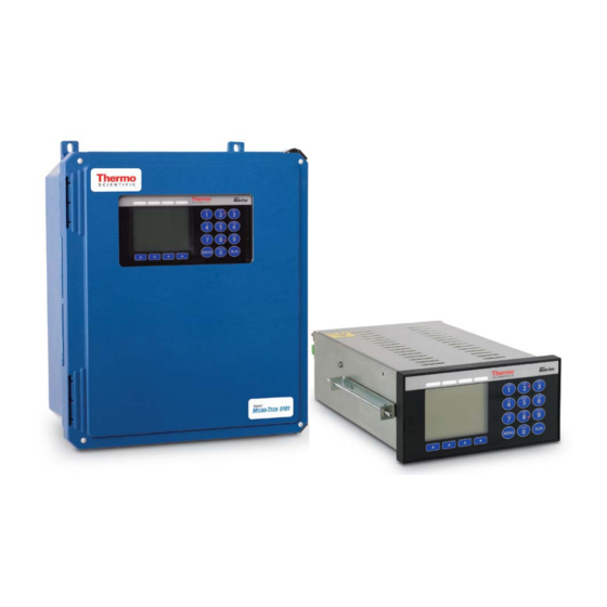
Page 20: Figure 1-1. Field-Mounted Version Of The Micro-Tech
(see Figure 1–2 for dimensions) in the panel and, after removing the holding brackets and installing the gasket, insert the Micro-Tech. Figure 1–1. Field-Mounted Version of the Micro-Tech Micro-Tech 9101/9201 Reference Manual, Rev J Thermo Fisher Scientific... -
Page 21: Figure 1-2. Panel-Mounted Version Of The Micro-Tech
Introduction Overview of the Micro-Tech Figure 1–2. Panel-Mounted Version of the Micro-Tech Thermo Fisher Scientific Micro-Tech 9101/9201 Reference Manual, Rev J... -
Page 22: Important Safety Information
WARNING. Covers over the electronics should always remain in place during operation. They should be removed only for maintenance procedures with the machine’s power OFF. Be sure to replace all covers before resuming operation. Micro-Tech 9101/9201 Reference Manual, Rev J Thermo Fisher Scientific... - Page 23 WARNING. This equipment should not be operated or utilized in applications other than those stated in the original order. Thermo Fisher Scientific Micro-Tech 9101/9201 Reference Manual, Rev J...
-
Page 24: Incoming Power Safety
CAUTION. Verify that the input voltage is correct with an AC voltmeter before you connect it to the integrator. CAUTION. Earth ground must be provided to the integrator. Do not use conduit to provide this ground. Micro-Tech 9101/9201 Reference Manual, Rev J Thermo Fisher Scientific... -
Page 25: Emc Instructions
Never use a “megger” to check the wiring. A readily accessible disconnect device must be incorporated in the field wiring. This disconnect should be within easy reach of the Thermo Fisher Scientific Micro-Tech 9101/9201 Reference Manual, Rev J... -
Page 26: Installing The Field Model
It may be mounted up to 3,000 ft (914 m) from the scale. The figure below shows a typical installation. Figure 1–3. A Typical 9101 Field-Mounted Installation Micro-Tech 9101/9201 Reference Manual, Rev J Thermo Fisher Scientific... -
Page 27: Mounting
7. If additional I/O is required at the line voltages, these wires should be routed through a conduit hole on the bottom right of the enclosure. Leave ample loose wiring (typically 8 inches / 20 cm) to facilitate removing the terminal connectors. Thermo Fisher Scientific Micro-Tech 9101/9201 Reference Manual, Rev J... -
Page 28: Installing The Panel Model
A 1-inch (25mm) clearance on each side is necessary for inserting the chassis-holding brackets from the back after inserting the Micro-Tech. 1-10 Micro-Tech 9101/9201 Reference Manual, Rev J Thermo Fisher Scientific... -
Page 29: Mounting
Appendix A. NOTE. Setting jumpers and switches on the Micro-Tech motherboard must be performed only by qualified service personnel. Thermo Fisher Scientific Micro-Tech 9101/9201 Reference Manual, Rev J 1-11... -
Page 30: Micro-Tech Features
Two load-cell inputs (J16, J21) on a Model 9101 or one load-cell input (J9) on a Model 9201, to a max of 6 load cells. USB port. Two serial communication ports. 1-12 Micro-Tech 9101/9201 Reference Manual, Rev J Thermo Fisher Scientific... -
Page 31: Micro-Tech Menus And Functions
When the belt is running and the rate is below a certain percentage, the Integrator can perform auto zero tracking, to minimize the error of zero due to material and dust. Analog (current) Thermo Fisher Scientific Micro-Tech 9101/9201 Reference Manual, Rev J 1-13... -
Page 32: Monitoring Functions
RS232C/RS-485 (jumper selectable), isolated. Comm B is RS-485 only, Functions non-isolated. One additional communication board may be installed. For detailed descriptions of communication protocols, see Appendix C. There are three types of standard communication functions, as described below. 1-14 Micro-Tech 9101/9201 Reference Manual, Rev J Thermo Fisher Scientific... -
Page 33: Overview Of Capabilities
(kg/h, ton/h, etc.). An adjustable damping filter is provided separately for displayed rate and current outputs. Flow Totalization Thermo Fisher Scientific Micro-Tech 9101/9201 Reference Manual, Rev J 1-15... -
Page 34: Automatic Zero And Span Calibrations
Allows you to run material of known weight over the scale to check the accuracy of your scale. Alternatively, you can run material over the scale, then have it re-weighed by another reference scale. 1-16 Micro-Tech 9101/9201 Reference Manual, Rev J Thermo Fisher Scientific... -
Page 35: Auto Zero Tracking
Outputs following signals Flow rate Belt loading Belt speed Each output has its own adjustable damping and programmable time or length delay. Thermo Fisher Scientific Micro-Tech 9101/9201 Reference Manual, Rev J 1-17... -
Page 36: Symbol Identification
9000 series comply with the EN and IEC standards listed below, when properly installed in accordance with this and other relevant manuals. CAN/CSA-C22.2 No.61010.1-04 Safety Requirements for Electrical Equipment for Measurement, 1-18 Micro-Tech 9101/9201 Reference Manual, Rev J Thermo Fisher Scientific... - Page 37 Information technology equipment. Radio disturbance characteristics. Limits and methods of measurement. ™ The Micro-Tech 9000 series complies with the following EN directives. 2006/95/CE—Low Voltage Directive. 2004/108/CE—EMC Directive. Thermo Fisher Scientific Micro-Tech 9101/9201 Reference Manual, Rev J 1-19...
-
Page 38: Specifications
Maximum Non-Destructive Input Voltage Field Mount: 265 VAC. Panel Mount: 28VDC. DC Power Supply Required for Panel Mount Output voltage: 24 VDC. Isolation: No. Output current: 2A minimum, short circuit protected. 1-20 Micro-Tech 9101/9201 Reference Manual, Rev J Thermo Fisher Scientific... - Page 39 Optical isolation: 250 VRMS max. Input Voltage: ±30 Vdc max. (RS-232C) ±15/-10 Vdc max. (RS-485). Cable length: RS-232C, 50ft [15m] max; RS-485, 4000 ft Thermo Fisher Scientific Micro-Tech 9101/9201 Reference Manual, Rev J 1-21...
- Page 40 Data Format: Asynchronous, bit-serial, selectable parity, data length, and stop bits. Isolation: Non-Isolated. Cable Length: 4000ft [1219m] max. Ethernet Communication Physical: 100baseT, RJ45 Ethernet port Embedded Web server Supported Protocols: Modbus TCP, Ethernet IP. 1-22 Micro-Tech 9101/9201 Reference Manual, Rev J Thermo Fisher Scientific...
-
Page 41: Initializing The Micro-Tech
Determine the exact belt length of the conveyor. Enter your belt-scale code and other conveyor and scale parameters into the Micro-Tech to initialize the software. Complete the initial scale (zero and span) calibrations. Thermo Fisher Scientific Micro-Tech 9101/9201 Reference Manual, Rev J... -
Page 42: Determining The Belt-Scale Code
For field- mounted versions, the Door Label is glued inside the main door of the enclosure. See Appendix A for an example of a typical Door Label. Micro-Tech 9101/9201 Reference Manual, Rev J Thermo Fisher Scientific... -
Page 43: Acquiring Basic System Data
If you have a non-pivoting scale—Go to the next page. If you have a pivoting* scale—Go to page 2-4. Thermo Fisher Scientific Micro-Tech 9101/9201 Reference Manual, Rev J... -
Page 44: Non-Pivoting Scales
* The example above, including the defaults, is for belt-scale code 49. Your weighing system will, most likely, have a slightly different list of required parameters and defaults. NOTE. For more information about the parameters listed above, please see pages 2-5 through 2-10. Micro-Tech 9101/9201 Reference Manual, Rev J Thermo Fisher Scientific... -
Page 45: The Next Step
Time to complete test revolutions (seconds) — * The example above, including the defaults, is for belt-scale code 1. Your weighing system will, most likely, have a slightly different list of required parameters and defaults. Thermo Fisher Scientific Micro-Tech 9101/9201 Reference Manual, Rev J... -
Page 46: Pivot-To-Load-Cell Distance
Distance Figure 2–1. Pivot-to-Load-Cell Distance Count the number of weight idlers and enter the result in Table 2–1 or Number of Weight Table 2–2. Idlers Figure 2–2. Number of Weight Idlers Micro-Tech 9101/9201 Reference Manual, Rev J Thermo Fisher Scientific... -
Page 47: Pivot-To-First-Idler Distance
If the static-weight option is installed, measure the length from the pivot Pivot-to-Test-Weight to the test weight, and enter the result in Table 2–1 or Table 2–2. If this Length option is not available, leave at the default value. Thermo Fisher Scientific Micro-Tech 9101/9201 Reference Manual, Rev J... -
Page 48: Pivot-To-Carriage Height
Table 2–2. If this option is not available, leave at the default value. Figure 2–7. Roller-to-Stringer Height Number of Load Cells Determine the number of load cells, and enter the result in Table 2–1 or Table 2–2. Micro-Tech 9101/9201 Reference Manual, Rev J Thermo Fisher Scientific... -
Page 49: Idler Spacing
If the conveyor slopes down, the angle is negative, meaning the conveyor has a negative incline. The appropriate sign (+ or –) for the incline must be entered in the appropriate Micro-Tech menu (see page 2-31). Thermo Fisher Scientific Micro-Tech 9101/9201 Reference Manual, Rev J... -
Page 50: Load Cell Capacity, Sensitivity, And Resistance
Two—You have two scales, each equipped with a speed sensor. Simulated—There is no speed sensor attached to your conveyor. Note, however, that a conveyor-run digital input is required for the simulated option to work. 2-10 Micro-Tech 9101/9201 Reference Manual, Rev J Thermo Fisher Scientific... -
Page 51: Test Duration
360 seconds is 4.80 (360/75). —Number of belt revolutions made in 6 minutes = 4.80 —Revs rounded up to the nearest whole number = 5 Thermo Fisher Scientific Micro-Tech 9101/9201 Reference Manual, Rev J 2-11... -
Page 52: Manually Determine Test Duration
5. Calculate (to at least one decimal place) the number of revolutions the belt makes in six minutes—as described in the example above. Round up the number of revolutions to the next whole number. Enter 2-12 Micro-Tech 9101/9201 Reference Manual, Rev J Thermo Fisher Scientific... -
Page 53: The Next Steps
There are no shortcuts! There are five steps in the software initialization process, as follows. Overview Enter the correct date and exact current time. Choose the appropriate language for the display. Thermo Fisher Scientific Micro-Tech 9101/9201 Reference Manual, Rev J 2-13... -
Page 54: Cold-Starting The Micro-Tech
You are now ready to set the current date and time. (In the following Setting the Date example we are going to set the date to May 21, 2013.) READY BATCH ALARM CALIB Install Factory Defaults? 2-14 Micro-Tech 9101/9201 Reference Manual, Rev J Thermo Fisher Scientific... - Page 55 Tech will not display the correct date in the Date line until you have completed the entire process. You can change the date and time formats later, if you would like to use a different one. Thermo Fisher Scientific Micro-Tech 9101/9201 Reference Manual, Rev J 2-15...
-
Page 56: Setting The Time
1. Press the down-arrow button (see Figure 3–1). The display should currently look like this. READY BATCH ALARM CALIB Exact time? - Time 12:00 am EDIT AM/PM 2-16 Micro-Tech 9101/9201 Reference Manual, Rev J Thermo Fisher Scientific... - Page 57 9. Press the “AM/PM” button to toggle the setting to “PM.” Your screen should now look something like this. READY BATCH ALARM CALIB Exact time? - Time 2:09 pm EDIT AM/PM Thermo Fisher Scientific Micro-Tech 9101/9201 Reference Manual, Rev J 2-17...
-
Page 58: Choosing A Language
1. The Micro-Tech display should currently look like this. READY BATCH ALARM CALIB - MEMORY ERASED - Choose the language key to continue to > ENGLISH < CHOICE ENTER CLEAR 2-18 Micro-Tech 9101/9201 Reference Manual, Rev J Thermo Fisher Scientific... -
Page 59: Entering Scale Data
“Press down SCROLL,” is a cue to press the down-arrow (or down-scroll) button, as described the next step (step 3). 3. Press the down-arrow button (or Scroll button) and the “Scale Data Scroll 1” screen appears. Thermo Fisher Scientific Micro-Tech 9101/9201 Reference Manual, Rev J 2-19... - Page 60 (The “Type of scale” scroll is not available on a model 9201 Micro-Tech.) 5. Press the down-arrow button to bring up the units menu. 2-20 Micro-Tech 9101/9201 Reference Manual, Rev J Thermo Fisher Scientific...
-
Page 61: Selecting English/Metric Units
5. In pages 2-20 through 2-24, do the following. Follow the “English” headings, if you are using English units. Follow the “Metric” headings, if you are using metric units. Thermo Fisher Scientific Micro-Tech 9101/9201 Reference Manual, Rev J 2-21... -
Page 62: Setting The Totalization Units
Choice button until the unit you want is displayed, then press the Enter button. 3. Press the down-arrow button to bring up the length units screen (go to page 2-22) 2-22 Micro-Tech 9101/9201 Reference Manual, Rev J Thermo Fisher Scientific... -
Page 63: Metric Totalization Units
The Micro-Tech display should currently look like this, if you chose English Length Units English units. READY BATCH ALARM CALIB - DISPLAY SCROLL 3 - Length Units > Feet < CHOICE Thermo Fisher Scientific Micro-Tech 9101/9201 Reference Manual, Rev J 2-23... -
Page 64: Metric Length Units
> meters < CHOICE 1. Meters is the default value. 2. As no other choices are available, press the down-arrow button to bring up the rate units screen (see the next section). 2-24 Micro-Tech 9101/9201 Reference Manual, Rev J Thermo Fisher Scientific... -
Page 65: Setting The Rate Units
“T/mn”—Standard tons per minute “Lt/mn”—Long tons per minute “percent %” “Lb/hr”—Pounds per hour 3. Press the down-arrow button to bring up the load-cell units screen (go to page 2-25). Thermo Fisher Scientific Micro-Tech 9101/9201 Reference Manual, Rev J 2-25... -
Page 66: Metric Rate Units
“kg/mn”—Kilograms per minute “t/mn”—Metric tonnes per minute “percent %” “kg/h”—Kilograms per hour 3. Press the down-arrow button to bring up the load-cell units screen (go to page 2-25). 2-26 Micro-Tech 9101/9201 Reference Manual, Rev J Thermo Fisher Scientific... -
Page 67: Mixed Rate Units
“T/mn—Standard tons per minute “LT/min”—Long tons per minute “percent %” “kg/h”—Kilograms per hour 3. Press the down-arrow button to bring up the load-cell units screen (see the next section). Thermo Fisher Scientific Micro-Tech 9101/9201 Reference Manual, Rev J 2-27... -
Page 68: Setting The Load-Cell Units
Choice button, then press the Enter button. 3. Press the down-arrow button to bring up the maximum scale- capacity screen (see the next section). 2-28 Micro-Tech 9101/9201 Reference Manual, Rev J Thermo Fisher Scientific... -
Page 69: Entering The Maximum Scale Capacity
Whatever value you enter cannot contain more than seven characters, including the decimal point. The maximum rate (that is, the scale capacity) cannot exceed 200,000 units of measure. Thermo Fisher Scientific Micro-Tech 9101/9201 Reference Manual, Rev J 2-29... -
Page 70: Entering The Scale Divisions
(programmable logic controller), you may need to choose a smaller (or larger) scale division. The Micro-Tech display should look something like this. READY BATCH ALARM CALIB - SC DATA SCROLL 3 - Scale divisions > 1 < CHOICE 2-30 Micro-Tech 9101/9201 Reference Manual, Rev J Thermo Fisher Scientific... -
Page 71: Entering The Belt-Scale Code
NOTE. You absolutely must enter the correct belt-scale code in this menu for the Micro-Tech to work properly with your particular weighing system. This is the most critical step in the entire set-up process! Thermo Fisher Scientific Micro-Tech 9101/9201 Reference Manual, Rev J 2-31... -
Page 72: Entering The Appropriate Conveyor Data
Table 2–1 or Table 2–2. Make sure you have these in front of you, as you work through the following Micro-Tech set-up menus. 2. Make sure the screen shown in Figure 2–11 above is currently being displayed. 2-32 Micro-Tech 9101/9201 Reference Manual, Rev J Thermo Fisher Scientific... -
Page 73: Pivot-To-Load-Cell Distance
The roller-to-stringer height is explained in Figure 2–7. Check the Roller-to-Stringer value. Press the down-arrow button to move on. Height Check the value, then press the down-arrow button to move on. Number of Load Cells Thermo Fisher Scientific Micro-Tech 9101/9201 Reference Manual, Rev J 2-33... -
Page 74: Idler Spacing
Single—Your conveyor is equipped with one speed sensor. Two—You have two conveyors, each equipped with a speed sensor. Simulated—There is no speed sensor attached to your conveyor(s). 2-34 Micro-Tech 9101/9201 Reference Manual, Rev J Thermo Fisher Scientific... -
Page 75: Establish Test Duration
2. To accept the long-duration test (code = 1), press the down-arrow button and the following screen appears. READY BATCH ALARM CALIB - CAL DATA SCROLL 12 - Establish test duration MANUAL Thermo Fisher Scientific Micro-Tech 9101/9201 Reference Manual, Rev J 2-35... - Page 76 EDIT ABORT 5. Press the Edit button and use the keypad to enter the length of the belt. (We entered 120 feet, as described in our example on page 2- 2-36 Micro-Tech 9101/9201 Reference Manual, Rev J Thermo Fisher Scientific...
- Page 77 EDIT ABORT 9. Press the Edit button. Use the keypad to enter the number you calculated earlier (and entered in Table 2–1 or Table 2–2) for the Thermo Fisher Scientific Micro-Tech 9101/9201 Reference Manual, Rev J 2-37...
- Page 78 The Micro-Tech is now performing the initial zero calibration—as shown by the Calibration LED, which comes on. READY BATCH ALARM CALIB Tim. belt travel 375 sec ABORT 2-38 Micro-Tech 9101/9201 Reference Manual, Rev J Thermo Fisher Scientific...
- Page 79 13. Press the Continue button and the following screen appears. The Micro-Tech is now setting the appropriate span number for the scale. READY BATCH ALARM CALIB SETUP progress Thermo Fisher Scientific Micro-Tech 9101/9201 Reference Manual, Rev J 2-39...
- Page 80 Micro-Tech. If the calibration fails again, check the load cell (or cells) are working and sending signals to the Micro-Tech. 15. After a brief pause, the following screen appears. READY BATCH ALARM CALIB Press RUN to start or MENU for scrolls 2-40 Micro-Tech 9101/9201 Reference Manual, Rev J Thermo Fisher Scientific...
-
Page 81: The Next Step
This is a very important step, because the scale will not give accurate readings until these calibrations are done. NOTE. You must perform an initial zero and span calibration before operating your scale. Thermo Fisher Scientific Micro-Tech 9101/9201 Reference Manual, Rev J 2-41... -
Page 83: Chapter 3 Operation
There are four major parts to the Micro-Tech console, as follows. Using the Display screen Console Keypad Soft keys Status LEDs Figure 3–1. Main Features of the Micro-Tech Console Thermo Fisher Scientific Micro-Tech 9101/9201 Reference Manual, Rev J... -
Page 84: Soft Key Buttons
Edit, Clear, Reset, Totals, and so forth. The status LEDs above the display, when lighted, alert you to the fact Status LEDs that the Micro-Tech is currently in either the Ready, Batch, Alarm, or Calibration mode. Micro-Tech 9101/9201 Reference Manual, Rev J Thermo Fisher Scientific... -
Page 85: Running The Micro-Tech
(Tons) that have crossed the scale since the values were last reset, as well as the tons per hour (Tph) of material that is currently running over the scale. READY BATCH ALARM CALIB 0.0 Tons 0.0 Tph TOTALS Figure 3–2. Run Screen Thermo Fisher Scientific Micro-Tech 9101/9201 Reference Manual, Rev J... -
Page 86: Viewing The Totals
Reset Total This total can be reset. Operator Total This is a second resettable total and records the total for an individual operator, if you have set up this feature. Micro-Tech 9101/9201 Reference Manual, Rev J Thermo Fisher Scientific... -
Page 87: Resetting The Reset And Operator Totals
BATCH ALARM CALIB RESET TOTAL SINCE 05-21-2013 12.7 Tons RESET 3. Press the Reset button and the confirmation screen appears. READY BATCH ALARM CALIB Do you wish to clear RESET Total? Thermo Fisher Scientific Micro-Tech 9101/9201 Reference Manual, Rev J... -
Page 88: Calibrating The Micro-Tech
1. Make sure the Run screen (see Figure 3–2) is currently being displayed. 2. Press the Menu button and the “Main Menu 1” screen appears. READY BATCH ALARM CALIB MAIN MENU 1 Press MENU for more ZERO CAL SPAN CAL MATL CAL Micro-Tech 9101/9201 Reference Manual, Rev J Thermo Fisher Scientific... - Page 89 5. The calibration time (in seconds) that you established during the Micro-Tech cold-start procedure, will start counting down. When the counter reaches zero, the calibration is complete and the change-zero screen appears. Thermo Fisher Scientific Micro-Tech 9101/9201 Reference Manual, Rev J...
- Page 90 19980 MENU 7. Press the Run soft key in the display to return the Micro-Tech to the Run mode. 8. Run several zero calibrations to assess the repeatability of the readings. Micro-Tech 9101/9201 Reference Manual, Rev J Thermo Fisher Scientific...
-
Page 91: Doing An R-Cal Span Calibration
If the R-Cal auto-span option (shown above) is not displayed, go to page B-5 to change the span calibration method. (For additional information about the Calibration menu, go to page B-22.) Thermo Fisher Scientific Micro-Tech 9101/9201 Reference Manual, Rev J... - Page 92 Micro-Tech cold-start procedure, will start counting down. When the counter reaches zero, the calibration is complete and the change-span screen appears. READY BATCH ALARM CALIB AUTOSPAN COMPLETE Change span? Error 0.01% 3-10 Micro-Tech 9101/9201 Reference Manual, Rev J Thermo Fisher Scientific...
- Page 93 Record the span results for future reference. (The numbering below is continued from page 3-8.) Thermo Fisher Scientific Micro-Tech 9101/9201 Reference Manual, Rev J 3-11...
- Page 94 MENU 7. Press the Run soft key in the display to return the Micro-Tech to the Run mode. 8. Run several span calibrations to assess the repeatability of the readings. 3-12 Micro-Tech 9101/9201 Reference Manual, Rev J Thermo Fisher Scientific...
-
Page 95: Maintenance And Troubleshooting
Check that all terminations are secure. Check to ensure the display, module, and keypad connectors are firmly seated in their connectors. Check that all jumpers are in their correct position. Thermo Fisher Scientific Micro-Tech 9101/9201 Reference Manual, Rev J... -
Page 96: Frequently Asked Questions
“Yes” each time to change the when there is an error, press the “No” button—as any additional tests are zero or span? for repeatability, which is a maintenance feature of calibrations. Micro-Tech 9101/9201 Reference Manual, Rev J Thermo Fisher Scientific... -
Page 97: Load-Cell Problems
Six-wire load cell—with field sense leads. A load-cell signal failure is usually caused by one of the following. Overview Failed load cell Bad or incorrect wiring Failed A/D converter Thermo Fisher Scientific Micro-Tech 9101/9201 Reference Manual, Rev J... - Page 98 Weight at the load cell 103009 A/D Gross 2 mV/V Total load cell capacity Weight at the load cell 68673 A/D Gross 1.8 mV/V Total load cell capacity Weight at the load cell 61806 Micro-Tech 9101/9201 Reference Manual, Rev J Thermo Fisher Scientific...
-
Page 99: Four-Wire Load-Cell, No Sense Leads
Model 9101 Sense Jumpers shown Cell, No Sense below. See “Appendix A – Premium A/D Jumper Locations” for Model Leads 9201 jumper locations. Figure 4–1. Four-Wire Load-Cell, No Sense Leads Thermo Fisher Scientific Micro-Tech 9101/9201 Reference Manual, Rev J... -
Page 100: Four Wire Load-Cell, With Sense Leads
Six-Wire Load- six-wire load cells with field sense leads. Model 9101 Sense Jumpers Cell With Sense shown below. See “Appendix A – Premium A/D Jumper Locations” for Leads Model 9201 jumper locations. Micro-Tech 9101/9201 Reference Manual, Rev J Thermo Fisher Scientific... - Page 101 4. Verify load-cell mV output at junction box. Disconnect load-cell signal wires from junction box. (terminals 22 and 23). Is load cell mV output within range of mV/V? If NO—Replace load cell. If YES—Load-cell circuitry is good. Thermo Fisher Scientific Micro-Tech 9101/9201 Reference Manual, Rev J...
-
Page 102: Analog Input/Output Problems
This section helps you troubleshoot the Micro-Tech’s analog Analog input/output circuitry. There are two types of optional analog output Input/Output printed-circuit board assemblies, as follows. Problems Populated (dual out and dual in) Micro-Tech 9101/9201 Reference Manual, Rev J Thermo Fisher Scientific... -
Page 103: Overview
Analog input (IO Define Scroll 2). In addition, an analog output can be forced to a specific value in “Main Menu 3,” as follows. Test Scroll 5A (analog output #1). Thermo Fisher Scientific Micro-Tech 9101/9201 Reference Manual, Rev J... -
Page 104: Procedure
If BAD—Replace either the analog board or the CPU board. Figure 4–4. Analog Troubleshooting—Confirm Voltage 2. Confirm analog output. Disconnect remote device(s). If GOOD—Proceed to “Confirm analog loop” (see step 3) If BAD—Replace analog board. 4-10 Micro-Tech 9101/9201 Reference Manual, Rev J Thermo Fisher Scientific... -
Page 105: Figure 4-5. Analog Troubleshooting-Confirm Output
3. Confirm analog loop. If GOOD—Analog board is performing as expected. If BAD—A problem exist in either with the field wiring or in the remote device. Figure 4–6. Analog Troubleshooting—Confirm Loop Thermo Fisher Scientific Micro-Tech 9101/9201 Reference Manual, Rev J 4-11... -
Page 106: Figure 4-7. Analog Troubleshooting-Verify Input
Figure 4–7. Analog Troubleshooting—Verify Input 6. Verify output of source device. Disconnect field wires and measure mA (volt) output of remote device. If GOOD—Proceed to “Verify mA loop” (see step 7). 4-12 Micro-Tech 9101/9201 Reference Manual, Rev J Thermo Fisher Scientific... -
Page 107: Figure 4-8. Analog Troubleshooting-Verify Source Output
7. Verify mA loop circuit. Place mA meter in series with analog loop. If GOOD—Input circuit is good. If BAD—Replace analog output board. Figure 4–9. Analog Troubleshooting—Verify mA Loop Thermo Fisher Scientific Micro-Tech 9101/9201 Reference Manual, Rev J 4-13... -
Page 108: Opto22 Problems
2. Press the Test button, then press the down-arrow button until the Digital Output Test screen appears. READY BATCH ALARM CALIB - TEST SCROLL 4 - Dig output test Output #1 EDIT ON/OFF 4-14 Micro-Tech 9101/9201 Reference Manual, Rev J Thermo Fisher Scientific... -
Page 109: Test Procedure For The Output Module
If GOOD—Digital output circuitry is functioning as expected. If BAD—Proceed to “Ohm Opto22 fuse” (see step 3). 3. Ohm Opto22 fuse. Remove and ohm the Opto22 4-amp fuse. Thermo Fisher Scientific Micro-Tech 9101/9201 Reference Manual, Rev J 4-15... -
Page 110: Figure 4-10. Opto22 Troubleshooting-Output Module
LED indicate the appropriate logic condition? If GOOD—Replace the Opto22 output module. If BAD—Replace either the Opto22 output module or the Micro- Tech CPU board. Figure 4–10. Opto22 Troubleshooting—Output Module 4-16 Micro-Tech 9101/9201 Reference Manual, Rev J Thermo Fisher Scientific... -
Page 111: Test Procedure For The Input Module
Inputs 1 and 2 are reserved for the speed input. 2. Voltage input. Measure source voltage input. If GOOD—Proceed to “View Opto LED” (see step 3). If BAD—Apply appropriate voltage to input terminals. Thermo Fisher Scientific Micro-Tech 9101/9201 Reference Manual, Rev J 4-17... -
Page 112: Figure 4-11. Opto22 Troubleshooting-Input Module
3. View Opto LED. With input voltage supplied, LED should be lit. If GOOD—Replace either the Opto22 input module or the Micro-Tech CPU board. If BAD—Replace the Opto22 input module. Figure 4–11. Opto22 Troubleshooting—Input Module 4-18 Micro-Tech 9101/9201 Reference Manual, Rev J Thermo Fisher Scientific... -
Page 113: Test Procedure For Eight In/Out Digital Board
4-12 to display the “Digital Input Test” screen shown below. READY BATCH ALARM CALIB -TEST SCROLL 3 - Dig input test Slot #0 00111 NEXT 2. Monitor the open collector Inputs 6–13. Figure 4–12. DIO Troubleshooting—Inputs 6–13 Thermo Fisher Scientific Micro-Tech 9101/9201 Reference Manual, Rev J 4-19... -
Page 114: Figure 4-13. Dio Troubleshooting-Sourcing
Maintenance and Troubleshooting Opto22 Problems 3. Outputs—Sourcing. Force the output number open/closed. Figure 4–13. DIO Troubleshooting—Sourcing 4. Outputs—Sinking. Figure 4–14. DIO Troubleshooting—Sinking 4-20 Micro-Tech 9101/9201 Reference Manual, Rev J Thermo Fisher Scientific... -
Page 115: On-Screen Warnings
Asterisks indicate an out-of-range span calculation. 1. Verify a load was applied to scale. Verify your set-up data. 2. Press the No button. 3. If you press the Yes button, a setting error-message is displayed. Thermo Fisher Scientific Micro-Tech 9101/9201 Reference Manual, Rev J 4-21... -
Page 116: Slot #X Change
The “No Speed Pulses” warning can occur during a number of No Speed Pulses procedures, as described below. While Doing a Zero or Span Calibration READY BATCH ALARM CALIB WARNING Belt stopped Calibration aborted EXIT 4-22 Micro-Tech 9101/9201 Reference Manual, Rev J Thermo Fisher Scientific... - Page 117 BATCH ALARM CALIB WARNING EQUIPMENT MAY START CONTINUE ABORT During certain set-up procedures, the user-configured safety interlocks may be affected by changing certain parameters, such as the digital input/output configurations. Thermo Fisher Scientific Micro-Tech 9101/9201 Reference Manual, Rev J 4-23...
-
Page 119: Service, Repair, And Replacement Parts
Hazard Declaration Form before returning anything to Thermo Fisher Scientific. For more information about contacting Thermo Fisher Scientific, see page 5-2. The Return Material Authorization (RMA) form you will need before returning your Micro-Tech to Thermo Fisher Scientific. Thermo Fisher Scientific Micro-Tech 9101/9201 Reference Manual, Rev J... -
Page 120: Getting Ready To Order
4. Then contact Thermo Fisher Scientific by email, fax, or telephone— as described on the following page. WARNING. Major repairs and/or modifications to your Micro-Tech must be performed by Thermo Fisher Scientific personnel. Micro-Tech 9101/9201 Reference Manual, Rev J Thermo Fisher Scientific... -
Page 121: Contacting Thermo Fisher Scientific
+52 55 1253 9410 +44 (0) 1452-415156 fax +52 55 1253 9424 fax Australia South Africa +61 (0) 8 8208-8200 +27 (0) 11-609-3101 +61 (0) 8 8234-3772 fax +27 (0) 11-609-3110 fax service.auadl@thermofisher.com Thermo Fisher Scientific Micro-Tech 9101/9201 Reference Manual, Rev J... -
Page 122: Parts List
MODULE,POWER,IN,280VAC, G4- 5 050480 MODULE,POWER,IN, 32VDC, G4- 5 044551 MODULE,POWER,OUT,240VAC, G4- 5 037289 MODULE,POWER,OUT, 60VDC, G4- 5 039669 MODULE,POWER,OUT,DRY,N/O,G4- 5 044552 FUSE, FAST-BLOW, 2A, 250V, 5X20MM 103190 DRIVE,FLASH,USB 2, 4GB,BRANDED 112183 Micro-Tech 9101/9201 Reference Manual, Rev J Thermo Fisher Scientific... -
Page 123: Appendix A Additional Installation Information
Appendix A Additional Installation Information The following page shows a copy of a typical System Data Sheet for the System Data Micro-Tech. Sheet Thermo Fisher Scientific Micro-Tech 9101/9201 Reference Manual, Rev J... - Page 124 Micro-Tech 9101/9201 Reference Manual, Rev J Thermo Fisher Scientific...
-
Page 125: Door Label
Here is a copy of a typical Door Label for the Micro-Tech. Door Label Thermo Fisher Scientific Micro-Tech 9101/9201 Reference Manual, Rev J... -
Page 126: Belt-Scale Codes
10-22 18-36 50-34 10-22 42-48 50-34 52.75 16.75 10-22 42-48 50-34 61.75 19.75 10-22 42-48 50-34 70.75 22.75 10-20-WF 10-20-WF 22.75 22.75 10-20-WF 10-20-WF 22.75 10-17-2 50-17 -4.75 10-17-2 50-17 -4.75 Micro-Tech 9101/9201 Reference Manual, Rev J Thermo Fisher Scientific... - Page 127 -4.5 70.87 23.62 62.99 78.74 39.37 -4.5 78.74 23.62 70.87 86.61 47.24 -4.5 90.55 23.62 82.68 98.43 59.06 -4.5 60.5 16.5 49.5 71.5 -4.5 -4.5 73.31 86.62 -4.5 -4.5 -4.5 -4.5 Thermo Fisher Scientific Micro-Tech 9101/9201 Reference Manual, Rev J...
- Page 128 23.62 47.24 39.37 39.37 10-101R-1 50-30 39.37 10-101R-2 50-30 39.37 39.37 31.50 25.59 39.37 -6.42 5.43 5.31 39.37 31.50 25.59 47.24 -6.42 5.43 5.31 39.37 31.50 25.59 39.37 -8.39 7.40 6.30 Micro-Tech 9101/9201 Reference Manual, Rev J Thermo Fisher Scientific...
- Page 129 39.37 19.69 19.69 19.69 39.37 39.37 19.69 19.69 19.69 39.37 39.37 19.69 19.69 19.69 39.37 66.93 59.06 19.69 59.06 19.69 72.83 39.37 39.37 39.37 39.37 See next page for additional information Thermo Fisher Scientific Micro-Tech 9101/9201 Reference Manual, Rev J...
-
Page 130: Establishing Belt-Length-Test Duration
1,000 feet. In addition, using the Partial method may be less accurate than using the Full method. Zero and span calibrations are the most accurate when using complete passes of the belt. Micro-Tech 9101/9201 Reference Manual, Rev J Thermo Fisher Scientific... -
Page 131: Partial Belt-Length Method
ALARM CALIB ACQUIRE TEST DUR Choose belt length measuring method FULL PARTIAL 2. Mark and measure a section of the belt. The section you mark must be longer than 200 feet. Thermo Fisher Scientific Micro-Tech 9101/9201 Reference Manual, Rev J... - Page 132 Ent. len. between two marks on belt. Length EDIT ABORT 6. Press the Start button. READY BATCH ALARM CALIB Start belt. Press START when 1 mark passes reference. START ABORT A-10 Micro-Tech 9101/9201 Reference Manual, Rev J Thermo Fisher Scientific...
- Page 133 COUNT ABORT DONE 9. After the last revolution has been counted, press the Done button. READY BATCH ALARM CALIB TEST DURATION Length = 600.0 ft Time = 360 sec EXIT Thermo Fisher Scientific Micro-Tech 9101/9201 Reference Manual, Rev J A-11...
-
Page 134: Full Belt-Length Method
1. Make a chalk mark on the belt. 2. Press the Acquire button and the following screen appears. READY BATCH ALARM CALIB ACQUIRE TEST DUR Choose belt length measurement method FULL PARTIAL A-12 Micro-Tech 9101/9201 Reference Manual, Rev J Thermo Fisher Scientific... - Page 135 Ent. len. of one belt revolution. Length ENTER ABORT CLEAR 5. Press the Start button. READY BATCH ALARM CALIB Start belt. Press START when 1 mark passes reference. START ABORT Thermo Fisher Scientific Micro-Tech 9101/9201 Reference Manual, Rev J A-13...
- Page 136 1 rev COUNT ABORT DONE 8. After the last revolution is counted, press the Done button. READY BATCH ALARM CALIB TEST DURATION Length = 1000 ft Time = 360 sec EXIT A-14 Micro-Tech 9101/9201 Reference Manual, Rev J Thermo Fisher Scientific...
-
Page 137: Material Factoring
Reset Weight Factor 1. Press the Menu button twice to bring up “Main Menu 2.” READY BATCH ALARM CALIB MAIN MENU 2 Press MENU for more SCALE CALIB DISPLAY DATA DATA Thermo Fisher Scientific Micro-Tech 9101/9201 Reference Manual, Rev J A-15... - Page 138 % EDIT NEXT 4. Press the Next button and the Weights screen appears. READY BATCH ALARM CALIB - CAL DATA SCROLL 10 - Material FACTOR Weights x.xx % EDIT NEXT A-16 Micro-Tech 9101/9201 Reference Manual, Rev J Thermo Fisher Scientific...
-
Page 139: Static Weight
Static Weight error. 1. Press the Menu button to bring up the “Main Menu 1” screen. READY BATCH ALARM CALIB MAIN MENU 1 Press MENU for more ZERO SPAN MATL Thermo Fisher Scientific Micro-Tech 9101/9201 Reference Manual, Rev J A-17... -
Page 140: Auto Span
The auto-span procedure determines the percent of scale weight span Auto Span error. 1. Add your test weight to the conveyor. READY BATCH ALARM CALIB AUTO SPAN Weights Apply weights then press START START EXIT A-18 Micro-Tech 9101/9201 Reference Manual, Rev J Thermo Fisher Scientific... -
Page 141: Record Results
4. When the Auto Span procedure is completed, the span percent-error is displayed. Record the results and note whether the error is positive or negative. Record Results READY BATCH ALARM CALIB AUTO SPAN COMPLETE Change Span? Error x.xx % Thermo Fisher Scientific Micro-Tech 9101/9201 Reference Manual, Rev J A-19... - Page 142 ! ! 3. Press the Run button and the Micro-Tech Run screen reappears, as shown below. READY BATCH ALARM CALIB xxxxx.x Tons xxx.x Tph TOTALS A-20 Micro-Tech 9101/9201 Reference Manual, Rev J Thermo Fisher Scientific...
- Page 143 % EDIT NEXT 6. Press the Next button and the Weights screen appears. READY BATCH ALARM CALIB - CAL DATA SCROLL 10 - Material FACTOR Weights x.xx % EDIT NEXT Thermo Fisher Scientific Micro-Tech 9101/9201 Reference Manual, Rev J A-21...
- Page 144 Material FACTOR Weights x.xx % ENTER +/– CLEAR 8. Press the Run button and the Micro-Tech Run screen reappears, as shown below. READY BATCH ALARM CALIB xxxxx.x Tons xxx.x Tph TOTALS A-22 Micro-Tech 9101/9201 Reference Manual, Rev J Thermo Fisher Scientific...
-
Page 145: Motherboard Terminal Block Definitions
SHIELD (EARTH) + EXCITATION – EXCITATION + SENSE – SENSE + SIGNAL – SIGNAL Load Cell 2 SHIELD (EARTH) + EXCITATION – EXCITATION + SENSE – SENSE + SIGNAL – SIGNAL Thermo Fisher Scientific Micro-Tech 9101/9201 Reference Manual, Rev J A-23... - Page 146 CTS/DCO UART GND (ISOLATED) SHIELD (EARTH) Speed signal (SPU) input and Output #5 +24VDC SIGNAL 1 (SPU) COMMON SHEILD (EARTH) SIGNAL 2 (SPU) 24VDC POWER OUTPUT #5 (24V) (OPEN-DRAIN) COMMON A-24 Micro-Tech 9101/9201 Reference Manual, Rev J Thermo Fisher Scientific...
-
Page 147: Premium A/D Terminal Block Definitions
Definitions Premium A/D Load Cell Shield (Earth GND) Signal COM + Excitation (+5v) - Excitation (-5v) + Excitation Sense - Excitation Sense + Load Cell Signal - Load Cell Signal Thermo Fisher Scientific Micro-Tech 9101/9201 Reference Manual, Rev J A-25... -
Page 148: Motherboard Jumper Locations
Here are the jumper locations the Micro-Tech motherboard. Motherboard Jumper Locations A-26 Micro-Tech 9101/9201 Reference Manual, Rev J Thermo Fisher Scientific... -
Page 149: Premium A/D Jumper Locations
Here are the Load Cell jumper locations of the Premium A/D board Premium A/D (Model 9201 Micro-Tech only.) Jumper Locations Thermo Fisher Scientific Micro-Tech 9101/9201 Reference Manual, Rev J A-27... -
Page 150: Motherboard Jumper Settings
Pull-down on TCLK_PSTCLK service personnel.) J5 Not Installed Jumper Setting Description (This jumper position must not be altered by either the user or by field Installed Enable bootloader program/erase service personnel.) A-28 Micro-Tech 9101/9201 Reference Manual, Rev J Thermo Fisher Scientific... - Page 151 J19 1-2 Installed Pins 1-2 Local Sense Channel 2 J20 1-2 Installed Pins 2-3 Remote Sense Channel 2 Not Installed Remote Sense Channel 2 Optional R-CAL resistor Channel 2 J22 Not Installed Thermo Fisher Scientific Micro-Tech 9101/9201 Reference Manual, Rev J A-29...
- Page 152 J28 Speed input 1 cutoff, J30 Speed input 2 cutoff Jumper Setting Description J28 Installed 1-2 Pins 1-2 Speed Input Cut-off 13kHz J30 Installed 1-2 Pins 2-3 Speed Input Cut-off 425 Hz Not Installed Speed Input Cut-off 13kHz A-30 Micro-Tech 9101/9201 Reference Manual, Rev J Thermo Fisher Scientific...
- Page 153 Enable RS-485 Termination COMM A Termination, (UART 0) Jumper Setting Description J42 Installed 1-2 Pins1-2 1.2kΩ termination enable J43 Installed 1-2 Pins 2-3 600Ω Bias Enabled Not Installed No additional termination Thermo Fisher Scientific Micro-Tech 9101/9201 Reference Manual, Rev J A-31...
-
Page 154: Premium A/D Jumper Settings
Jumper Settings Default Jumper Setting Description J2 1-2 Installed Pins 1-2 Local sensing (4-wire LC) J3 1-2 Installed Pins 2-3 Remote sensing (6-wire LC) Not Installed Remote sensing (6-wire LC) A-32 Micro-Tech 9101/9201 Reference Manual, Rev J Thermo Fisher Scientific... -
Page 155: A/D Jumpers-Load-Cell Sense
6 wire system: cable distance not to exceed 3000ft [914m]. Excitation-Sense Circuitry Nominal input voltage: 5 VDC. (2 each) Input impedance: 100 k-ohm minimum. Jumper selectable: Local or remote sense. Thermo Fisher Scientific Micro-Tech 9101/9201 Reference Manual, Rev J A-33... -
Page 156: Table A-3. Premium A/D Board Load-Cell Technical Specifications (Model 9201
4 wire system: cable distance not exceed 200ft [61m]. 6 wire system: cable distance not to exceed 3000ft [914m]. Excitation-Sense Circuitry Nominal input voltage: ±5 VDC. Input impedance: 100 k-ohm minimum. Jumper selectable: Local or remote sense. A-34 Micro-Tech 9101/9201 Reference Manual, Rev J Thermo Fisher Scientific... -
Page 157: Programmable Digital Inputs/Outputs
Opto22 Output Board. Eight (8) programmable outputs on the optional Digital I/O 8in/8out Board. Two of these boards may be installed for a total of sixteen (16) outputs. Thermo Fisher Scientific Micro-Tech 9101/9201 Reference Manual, Rev J A-35... -
Page 158: Digital Input Expansion Boards
This is an optional board with three inputs (inputs #3–5). Type: Current sourcing to common ground. Designed for dry-contact input. Rated: 24VDC, 5mA typical. Input function is assigned by user. Part number = 100785 A-36 Micro-Tech 9101/9201 Reference Manual, Rev J Thermo Fisher Scientific... -
Page 159: Opto22 Input Board
32VDC In Module (G4IDC5) Input voltage range: 10-32VDC; 12-32VAC. Input current at maximum line: 25mA. Install in slots U1–U3 on the input board. Part number = 102999 Thermo Fisher Scientific Micro-Tech 9101/9201 Reference Manual, Rev J A-37... -
Page 160: Digital Output Expansion Boards
Rated: 70 VDC at 0.5A. Fusing requirement: 1A. Field version Rated: 240 VAC at 3A. Fusing requirement:5A. Rated: 70 VDC at 0.5A. Fusing requirement 1A. Part number = 102479 A-38 Micro-Tech 9101/9201 Reference Manual, Rev J Thermo Fisher Scientific... -
Page 161: Opto22 Output Board
Dry (Reed) Out Module, G4ODC5R. Contact rating: 10 VA. Maximum switching voltage: 100VDC, 130VAC. Maximum switching current: 0.5A. Replaceable 250V 1A fuse. Part number = 103003 Thermo Fisher Scientific Micro-Tech 9101/9201 Reference Manual, Rev J A-39... -
Page 162: Dio 8In/8Out Board
Approximately 12 mA of current flows out of each input during contact closure. Output current sinking or sourcing is selectable thru a menu screen. Inputs are always current sourcing. Board Diagram Part number = 103017 A-40 Micro-Tech 9101/9201 Reference Manual, Rev J Thermo Fisher Scientific... -
Page 163: Analog I/O Boards
Capacitive load: No limit Field wiring: Connections are made to the terminal strip on end of the 4-20mA Output Board. Note that connector is removable for ease of termination. Thermo Fisher Scientific Micro-Tech 9101/9201 Reference Manual, Rev J A-41... -
Page 164: Type B: Analog I/O Board
This is an optional board. Install in one of the motherboard expansion Type B: Analog slots J10–J13. I/O Board Inputs Incline compensation Moisture compensation Outputs Rate Speed Load A-42 Micro-Tech 9101/9201 Reference Manual, Rev J Thermo Fisher Scientific... - Page 165 Optically isolated Isolated power source Output Range (mA) 0 to 20 mA +4 to 20 mA Voltage output by adding an internal dropping resistor. Thermo Fisher Scientific Micro-Tech 9101/9201 Reference Manual, Rev J A-43...
-
Page 166: Dual-Plant Load-Cell A/D Board
R-Cal resistor. “Channel 1,” top connector has jumpers J14 and J15 that allow selection of either external excitation sense (6-wire LC hook-up) or internal excitation sense (4-wire LC hook-up). A-44 Micro-Tech 9101/9201 Reference Manual, Rev J Thermo Fisher Scientific... - Page 167 “loss-in-weight” applications. The standard board is hard-wired for 10 conversions per second. Altering the W2/W3 option jumpers allows software selection of the desired conversion rate, so do not change. Jumper Locations Thermo Fisher Scientific Micro-Tech 9101/9201 Reference Manual, Rev J A-45...
-
Page 168: Communication Board
Optical isolation, 250 Vrms max. Input voltage: ±30 Vdc max. (RS-232C) +15/-10 Vdc max. (RS-485) Cable length: 50 feet maximum (RS-232C) 4000 feet maximum (RS-485 and 20 mA) A-46 Micro-Tech 9101/9201 Reference Manual, Rev J Thermo Fisher Scientific... - Page 169 3. Remove the field mating connector. Wire the connector per the supplied field-wiring diagram at the end of the manual. 4. Remove the hex head mounting screw from the connector end of the COMM board. Thermo Fisher Scientific Micro-Tech 9101/9201 Reference Manual, Rev J A-47...
-
Page 170: Profibus-Dp Board
It is typically used to transfer I/O images between a main PLC and remote devices (sensors, actuators, transmitters, etc.). In this case, it will be used to transfer (read and write) blocks of data. A-48 Micro-Tech 9101/9201 Reference Manual, Rev J Thermo Fisher Scientific... - Page 171 Siemens that handles the interface between the Micro-Tech slave and the master. See page C-59 for details about the Profibus-DP option card. Board Diagram Part number = 102936 Thermo Fisher Scientific Micro-Tech 9101/9201 Reference Manual, Rev J A-49...
-
Page 173: Appendix B Micro-Tech Menu Details
ZERO Calibration—Performs a zero calibration on your scale. SPAN Calibration—Performs a span calibration on your scale. MATERIAL Calibration—Allows you to calibrate your scale using materials of known weight. Thermo Fisher Scientific Micro-Tech 9101/9201 Reference Manual, Rev J... - Page 174 Press MENU for more TEST This screen contains the following functions. DIAGNOSTICS Function—Allows you to view the speed signals, load-cell signals, and which version of the Micro-Tech software you are currently using. Micro-Tech 9101/9201 Reference Manual, Rev J Thermo Fisher Scientific...
- Page 175 Press MENU for more COMM A COMM A—This allows you to set the communication parameters for the COM A port on the Micro-Tech motherboard. Other communication parameters for option boards. Thermo Fisher Scientific Micro-Tech 9101/9201 Reference Manual, Rev J...
- Page 176 Micro-Tech calibrations. LINEARIZATION—Applies a factor to the span settings at multiple flow rates. Please see the following sections for more information about all Micro- Tech menus and functions. Micro-Tech 9101/9201 Reference Manual, Rev J Thermo Fisher Scientific...
-
Page 177: Main Menu 1
MANUAL ZERO EDIT, EXIT, ADV (Password: Operator) Rate Zero # XXXXX MANUAL ZERO EXIT, ADV AZ Dev - Shows the difference between the new zero number and the Zero AZ Dev Thermo Fisher Scientific Micro-Tech 9101/9201 Reference Manual, Rev J... -
Page 178: Span Calibration
1. Make sure the Micro-Tech Run screen is currently being displayed. READY BATCH ALARM CALIB 0.0 Tons 0.0 Tph TOTALS 2. Press the Menu button twice to bring up “Main Menu 2.” Micro-Tech 9101/9201 Reference Manual, Rev J Thermo Fisher Scientific... - Page 179 - CALIB DATA SCROLL 1 - Calibration mode > R-Cal < CHOICE 5. Press the Choice button repeatedly until the method you want to use appears in the screen, as shown below. Thermo Fisher Scientific Micro-Tech 9101/9201 Reference Manual, Rev J...
- Page 180 ALARM CALIB - CALIB DATA SCROLL 2 - R-Cal selected 165000 Ohms EDIT Test-Chain Method READY BATCH ALARM CALIB - CALIB DATA SCROLL 4 - Chain select. weight 0.000 Lb/Ft EDIT Micro-Tech 9101/9201 Reference Manual, Rev J Thermo Fisher Scientific...
- Page 181 Total test weight on scale 0.000 lbs EDIT Add up the total weight you added to the scale, press the Edit button, and use the keypad to enter the appropriate value. Thermo Fisher Scientific Micro-Tech 9101/9201 Reference Manual, Rev J...
-
Page 182: Span Calibration Instructions
With the “Load WTS” option selected, the test weights are automatically loaded after you press the Start button. Wait for the test weights to be loaded, before proceeding to the next step. B-10 Micro-Tech 9101/9201 Reference Manual, Rev J Thermo Fisher Scientific... - Page 183 If the Error is greater than 0.50% there may be a problem. Press No and see the troubleshooting section for additional help. Thermo Fisher Scientific Micro-Tech 9101/9201 Reference Manual, Rev J B-11...
- Page 184 Chain or Weights before returning to normal operation. READY BATCH ALARM CALIB READY BATCH ALARM CALIB REMOVE weight REMOVE chain before returning to before returning to normal operation!! normal operation!! MENU MENU B-12 Micro-Tech 9101/9201 Reference Manual, Rev J Thermo Fisher Scientific...
-
Page 185: Span Calibration Menu
Apply chain then press START AUTO SPAN Chain START, EXIT Run belt, then press START Remove Chains before returning to RUN, MENU normal operation! AUTO SPAN Weights START, EXIT, MANUAL Thermo Fisher Scientific Micro-Tech 9101/9201 Reference Manual, Rev J B-13... - Page 186 XXXX = R-CAL, CHAINS, before and the current simulated load method has Old factor % no material factor installed. New factor % MANUAL SPAN EDIT, EXIT Rate Span # B-14 Micro-Tech 9101/9201 Reference Manual, Rev J Thermo Fisher Scientific...
-
Page 187: Material Calibration
1,200.00 tons on an independent reference scale. 1. In the Run screen, press the Menu button and “Main Menu 1” screen appears. READY BATCH ALARM CALIB MAIN MENU 1 PRESS MENU for more ZERO SPAN MATL Thermo Fisher Scientific Micro-Tech 9101/9201 Reference Manual, Rev J B-15... - Page 188 Run belt empty, then press START START MENU 4. Make sure that the belt is running empty, then press the Start button. READY BATCH ALARM CALIB Run quantity of Material over scale. CONTINUE B-16 Micro-Tech 9101/9201 Reference Manual, Rev J Thermo Fisher Scientific...
- Page 189 Tons Ref. weight Known? Press the No button (meaning your reference weight is unknown) and the Run screen reappears. READY BATCH ALARM CALIB xxx.xx Tons xxx.x Tph TOTALS MATL Thermo Fisher Scientific Micro-Tech 9101/9201 Reference Manual, Rev J B-17...
- Page 190 Tons Enter reference weight xxx.xx • ENTER CLEAR 11. Press the Enter button and the following screen appears. READY BATCH ALARM CALIB MAT’L CAL. COMP. Error xx.xx % Change span? B-18 Micro-Tech 9101/9201 Reference Manual, Rev J Thermo Fisher Scientific...
- Page 191 Here is the Material Calibration menu table. Parameter Selection Description MAT’L CALIBRATION no, yes This scroll is only available when Linearization scroll 1 is set to Yes. 3 points linear. MAT’L CALIBRATION START, MENU Thermo Fisher Scientific Micro-Tech 9101/9201 Reference Manual, Rev J B-19...
- Page 192 ZZZZ = New factor, Old factor Change factor? XXXX Matl FACTOR RUN, MENU, FACTOR XXXX = R-CAL, WTS, CHAINS Old factor New factor MAT’L CALIBRATION YES, NO Add reference weight to totals? B-20 Micro-Tech 9101/9201 Reference Manual, Rev J Thermo Fisher Scientific...
-
Page 193: Display Menu
Time am/pm, 24h (Password: Service.) Date MM-DD-YYYY, YYYY- (Password: Service.) MM-DD, DD-MM- YYYY Run display line 3 No display, Speed, Optional Run Screen display line 3. Load, Date/Time (Password: Operator.) Thermo Fisher Scientific Micro-Tech 9101/9201 Reference Manual, Rev J B-21... -
Page 194: Scale Data Menu
This scroll is not applicable to the 9201. Max Scale 500 Tph (1 – Max Scale Capacity. Capacity 200000) Operating range 25 to 100%. Scales the analog ma output (Rate and Load). B-22 Micro-Tech 9101/9201 Reference Manual, Rev J Thermo Fisher Scientific... - Page 195 0.001, 50, 20, 10, 5, 2 Belt scale code # Enter code for Thermo Scientific scale models for default values entered in. Detail scrolls 4A-4O are dependent on the belt scale code and on the number of weigh idlers selected.
- Page 196 Refer to label at end of load cell cable or the applications data sheet from Thermo. Load cell #1 res. 350.000 Ohms Signal bridge resistance of load cell #1. (10-2000) B-24 Micro-Tech 9101/9201 Reference Manual, Rev J Thermo Fisher Scientific...
-
Page 197: Calibration Data Menu
Rcal calibration Chain select. weight 0.000 lb/ft (0.0 - 1000) Stamped weight per length of calibration chain(s). Chain cal constant Calculated (or factored) accumulated weight at end of simulated Chain calibration Thermo Fisher Scientific Micro-Tech 9101/9201 Reference Manual, Rev J B-25... -
Page 198: Establish Test Duration
Ent. len. between two (1 - 10,000 ft) marks on belt. Enter the number of (1 - 100 rev) Required belt revolutions to achieve belt revolutions to be minimum test time timed B-26 Micro-Tech 9101/9201 Reference Manual, Rev J Thermo Fisher Scientific... - Page 199 INVALID (0 - 120000) The base value for Autozero max deviation and Autozero Track max deviation. This value must be re-set to clear a Autozero or Autozero Track max deviation alarm. Thermo Fisher Scientific Micro-Tech 9101/9201 Reference Manual, Rev J B-27...
- Page 200 Mode is set to OIML or NONE, the Zero Ready scroll defaults to “No”. Whenever the Zero Ready scroll setting is changed an Audit Trail event is generated. (Password: Service.) B-28 Micro-Tech 9101/9201 Reference Manual, Rev J Thermo Fisher Scientific...
-
Page 201: Main Menu 3
Protection choices = None (the default), Limited, or Protected. Increasing the protection level does not require a password. A Service password is required to access the None level of protection. An Operator Thermo Fisher Scientific Micro-Tech 9101/9201 Reference Manual, Rev J B-29... -
Page 202: Decreasing The Protection Level
2. The display will prompt for a password. Press the Edit key to enter the password. Press Enter when complete. READY BATCH ALARM CALIB - PROTECTION LEVEL - > PROTECTED < PASSWORD EDIT B-30 Micro-Tech 9101/9201 Reference Manual, Rev J Thermo Fisher Scientific... -
Page 203: On-Line Procedure For Changing Protection Level
Operator password and the variable or function requires the Service password instead, access is denied and the following screen is displayed. READY BATCH ALARM CALIB - SYSTEM PROTECTED - PLEASE ENTER SERVICE PASSWORD ___________ EDIT Thermo Fisher Scientific Micro-Tech 9101/9201 Reference Manual, Rev J B-31... -
Page 204: Protection Menu Table
LIMITED – Operator functions and data are protected. All setup and calibration data are protected except zero calibrate. PROTECTED – The system is totally protected; process data can be read, but no changes are allowed. B-32 Micro-Tech 9101/9201 Reference Manual, Rev J Thermo Fisher Scientific... -
Page 205: Diagnostics Menu
To remove a password, just press EDIT and then ENTER. (Password: Service.) Enter OPERATOR Enter Operator password to enable password protection. Up to eight characters long. It is strongly recommended you write down Thermo Fisher Scientific Micro-Tech 9101/9201 Reference Manual, Rev J B-33... -
Page 206: Test Menu
Here is the Test menu table. Test Menu Parameter Selection Description LAMP TEST START Keypad LED’s blink on and off. Internal test of START Testing ROM, RAM, and microprocessor E2PROM. B-34 Micro-Tech 9101/9201 Reference Manual, Rev J Thermo Fisher Scientific... - Page 207 (Password: Service.) Current output #2 4.00 mA (4-20) (0-20) (20-0) “ should be ____ (20-4) Current output #3 4.00 mA (4-20) (0-20) (20-0) “ should be ____ (20-4) Thermo Fisher Scientific Micro-Tech 9101/9201 Reference Manual, Rev J B-35...
-
Page 208: Usb Menu
Micro-Tech must be formatted with 512-byte data sectors. The default sector-size applied when a USB device is formatted in Microsoft Windows, is not necessarily 512 bytes, so a special procedure is required. B-36 Micro-Tech 9101/9201 Reference Manual, Rev J Thermo Fisher Scientific... - Page 209 NOTE. The maximum capacity of the USB device that can be used in the Micro-Tech, is 1 GB. Higher capacity devices (> 1GB) require special partitioning tools to enable formatting with 512-byte sectors. Thermo Fisher Scientific Micro-Tech 9101/9201 Reference Manual, Rev J B-37...
- Page 210 1. Press the USB button and the following screen appears. READY BATCH ALARM CALIB - START OF SCROLL - Use SCROLL keys to view selections. 2. Press the down-arrow button and the “USB configuration” screen appears. B-38 Micro-Tech 9101/9201 Reference Manual, Rev J Thermo Fisher Scientific...
- Page 211 USB Configuration Archive settings SAVE RESTORE 1. Press the Save button and the following screens displays the progress of the save operation. READY BATCH ALARM CALIB USB Configuration Saving xx % Thermo Fisher Scientific Micro-Tech 9101/9201 Reference Manual, Rev J B-39...
- Page 212 2. Press the Restore button and the following screens displays the progress of the restore operation. READY BATCH ALARM CALIB USB Configuration Restoring xx % B-40 Micro-Tech 9101/9201 Reference Manual, Rev J Thermo Fisher Scientific...
-
Page 213: Printing To A Usb Flash Drive
Ethernet Menu Next 2 Year Month Code See Year/Month Table Next 1 Day Code See Day Code Table Last 1 Report number Report number for the day - 1-9, A-Z Thermo Fisher Scientific Micro-Tech 9101/9201 Reference Manual, Rev J B-41... - Page 214 CODE CODE CODE CODE CODE YEAR YEAR YEAR YEAR YEAR Jan-2012 Mar-2014 May-2016 Jul-2018 Sep-2020 Feb-2012 Apr-2014 Jun-2016 Aug-2018 Oct-2020 Mar-2012 May-2014 Jul-2016 Sep-2018 Nov-2020 Apr-2012 Jun-2014 Aug-2016 Oct-2018 Dec-2020 B-42 Micro-Tech 9101/9201 Reference Manual, Rev J Thermo Fisher Scientific...
- Page 215 Dec-2015 Feb-2018 Apr-2020 Jun-2022 Nov-2013 Jan-2016 Mar-2018 May-2020 Jul-2022 Dec-2013 Feb-2016 Apr-2018 Jun-2020 Aug-2022 Jan-2014 Mar-2016 May-2018 Jul-2020 Sep-2022 Feb-2014 Apr-2016 Jun-2018 Aug-2020 Oct-2022 Day Code Table CODE CODE CODE Thermo Fisher Scientific Micro-Tech 9101/9201 Reference Manual, Rev J B-43...
-
Page 216: Main Menu 4
Current out range 4-20 mA, 20-0 mA, 20-4 mA, 0- 20mA Current out delay (0-300 sec) (0-10,000 ft) #1 ___ #2 ___ #3 ___ #4 ___ Current out (0-400 sec) Damping B-44 Micro-Tech 9101/9201 Reference Manual, Rev J Thermo Fisher Scientific... - Page 217 Moisture calib. Hi position. Then enter the angle of the conveyor in this scroll. Enter the percent moisture and corresponding moisture sensor voltage for the high moisture point into this scroll. Thermo Fisher Scientific Micro-Tech 9101/9201 Reference Manual, Rev J B-45...
- Page 218 Normally Open (NO) or Normally Shut down 0 NC Closed (NC) status of the input. Ready 0 NO By assigning a function to 0, the function is disabled. High load 0 NO B-46 Micro-Tech 9101/9201 Reference Manual, Rev J Thermo Fisher Scientific...
- Page 219 Note: Only present when pulse width Totalizer output is defined. Type board 1 Source, Sink 8in8out Type board 2 Source, Sink 8in8out Clip detect mode Manual, Auto Clip detect length 1.0 ft (0.5-10) Thermo Fisher Scientific Micro-Tech 9101/9201 Reference Manual, Rev J B-47...
-
Page 220: Alarm Definitions Menu
The system has detected an error on the RAM (random-access memory) checksum during the internal periodic test. The RAM is used to store variables and set up data. Replace the motherboard. 4. ROM Fail B-48 Micro-Tech 9101/9201 Reference Manual, Rev J Thermo Fisher Scientific... - Page 221 Sets an alarm based on a percentage of the Belt Speed Capacity. Low speed set 10% (0 - 105%) ___ ___ 10 sec (0 - 90 sec) 60 FPM (0 - 630 FPM) Thermo Fisher Scientific Micro-Tech 9101/9201 Reference Manual, Rev J B-49...
- Page 222 ALARM, SHUT DOWN, AUTO Only present when Speed RES., NONE alarm is set to Yes. Low speed ALARM, SHUT DOWN, AUTO Only present when Speed RES., NONE alarm is set to Yes. B-50 Micro-Tech 9101/9201 Reference Manual, Rev J Thermo Fisher Scientific...
- Page 223 ALARM, SHUT DOWN, AUTO Only present when Printer is RES., NONE selected for Protocol port #1, or a COMM board is installed. This message is displayed if the system has data to print Thermo Fisher Scientific Micro-Tech 9101/9201 Reference Manual, Rev J B-51...
- Page 224 Load cell imbalance NONE, ALARM, SHUT DOWN, AUTO RES. Auto Zero Limit ALARM, SHUT DOWN, AUTO RES., NONE AZT step over limit ALARM, SHUT DOWN, AUTO RES., NONE B-52 Micro-Tech 9101/9201 Reference Manual, Rev J Thermo Fisher Scientific...
-
Page 225: Ethernet Settings Menu
Description Baud rate port #1 9600, 19200, 110, 150, 300, 600, 1200, 2400, 4800 Set parity port #1 No Parity, even parity, odd parity Stop bits port #1 1, 2 Thermo Fisher Scientific Micro-Tech 9101/9201 Reference Manual, Rev J B-53... - Page 226 Half duplex delay 0 msec (0 - 50 msec) Note: This scroll is only available when a protocol other than Printer is selected for either Protocol port #1 or Protocol port #2. B-54 Micro-Tech 9101/9201 Reference Manual, Rev J Thermo Fisher Scientific...
- Page 227 Display menu, without the scale division applied. "Displayed" shows the values as they would be shown on the Micro-Tech display with the scale division applied. Thermo Fisher Scientific Micro-Tech 9101/9201 Reference Manual, Rev J B-55...
-
Page 228: Profibus Menu
If the Micro-Tech detects a USB flash drive, the COM button is displayed, as shown below. READY BATCH ALARM CALIB PRINTER SCROLL Com # 1 no data Print SET UP PRINT B-56 Micro-Tech 9101/9201 Reference Manual, Rev J Thermo Fisher Scientific... - Page 229 3. Press the Print button to print the records you selected. READY BATCH ALARM CALIB - PRINT AUDIT TRAILS - Number of records to print xxx EDIT PRINT EXIT Thermo Fisher Scientific Micro-Tech 9101/9201 Reference Manual, Rev J B-57...
- Page 230 (Password: Service.) Print interval 0 (0-59 min) This feature repeatedly prints a Total 0 (0-23 hours) report to the serial printer at the specified 0 (0-365 days) time interval. B-58 Micro-Tech 9101/9201 Reference Manual, Rev J Thermo Fisher Scientific...
- Page 231 7 (0-24) X = ___ Y= ___ 1 (1-80) Position time 8 (0-24) X = ___ Y= ___ 1 (1-80) Position rate 9 (0-24) X = ___ Y= ___ 1 (1-80) Thermo Fisher Scientific Micro-Tech 9101/9201 Reference Manual, Rev J B-59...
-
Page 232: Main Menu 6
Linearization function is not normally used with conveyor-belt scales. In Menu case of extreme instances where calibration at multiple flow rates may be required, please consult a Thermo Fisher Scientific technical representative. B-60 Micro-Tech 9101/9201 Reference Manual, Rev J Thermo Fisher Scientific... - Page 233 This scroll is for flow rate under 80%. Load ______ 0.00 Lb/Ft " Fact. ________ 1.000000 (0-1.5) LINEARIZ. #5 This scroll is for flow rate under 100%. Load ______ 0.00 Lb/Ft " Fact. ________ 1.000000 (0-1.5) Thermo Fisher Scientific Micro-Tech 9101/9201 Reference Manual, Rev J B-61...
-
Page 235: Appendix C Communication Protocols
50 feet (15 m). Modem capability. RS485/RS422—For point-to-point or multi-drop 4-wire bi-directional communications, maximum 4,000 feet (1,200 m). One additional communication board may be installed, as described later in this appendix. Thermo Fisher Scientific Micro-Tech 9101/9201 Reference Manual, Rev J... -
Page 236: Comm Jumper Configurations
4-wire 2-wire multi-drop Transmit with hardware hand shake RCV terminated with 120 ohms pull-aside enable Wire to the J37 terminal block on the motherboard for the communication standard selected—RS-485 or RS-232C. Micro-Tech 9101/9201 Reference Manual, Rev J Thermo Fisher Scientific... -
Page 237: Built-In Protocols
Thermo Fisher Scientific declines any responsibility for any malfunction that may occur when connecting the instrument to devices of other manufacturers, unless tested and approved by Thermo Fisher Scientific. Thermo Fisher Scientific Micro-Tech 9101/9201 Reference Manual, Rev J... -
Page 238: Protocol Rules
0 (no error). If not, it is set to 1. To know if the last variables sent have been stored, the Master checks (reads) the success flag contained in a read-only register. Micro-Tech 9101/9201 Reference Manual, Rev J Thermo Fisher Scientific... -
Page 239: Printer
In this particular case, the user is able to easily format the printout to fit into any pre-printed ticket or form, without the need of special software. Thermo Fisher Scientific Micro-Tech 9101/9201 Reference Manual, Rev J... -
Page 240: Master/Slave Interactions
NOTE. The maximum number of words the system can transfer is 41 per time. Requests of registers in excess of 41 are treated as errors and do not generate an answer. Micro-Tech 9101/9201 Reference Manual, Rev J Thermo Fisher Scientific... -
Page 241: Register Definitions
• integer—16 bits IEEE integer (1 word) • long—32 bits IEEE long integer (2 words) • float—32 bits IEEE float (2 words) • double—64 bits IEEE double precision float (4 words) Thermo Fisher Scientific Micro-Tech 9101/9201 Reference Manual, Rev J... -
Page 242: Type, Limits, And Format Of Registers
Reset Total Scale Specific none Float Operator Total Scale Specific limited Float Batch Total Scale Specific limited Float Batch Setpoint Scale Specific 10000 limited Float Batch Preset Scale Specific 10000 limited Float Micro-Tech 9101/9201 Reference Manual, Rev J Thermo Fisher Scientific... -
Page 243: Description Of Registers
See Alarm Table on page C-13. See I/O Table on page C-15.. The number of audit trails to print. Entered or downloaded by the user. An integer Number Of trials value 1 to 999. Thermo Fisher Scientific Micro-Tech 9101/9201 Reference Manual, Rev J... - Page 244 Batch Preset Defines when the rate is lowered to increase batch accuracy. Batch Preact The set point of the pre-act for the current or the next Load Out. Entered or C-10 Micro-Tech 9101/9201 Reference Manual, Rev J Thermo Fisher Scientific...
- Page 245 ( 2 ) display ( 3 ) display ( 4 ) display ( 5 ) display ( 6 ) display ( 10 ) characters 19 and 20 from left of first row Thermo Fisher Scientific Micro-Tech 9101/9201 Reference Manual, Rev J C-11...
-
Page 246: Bit Definitions
LED #2 Green; (Applies to the currently displayed scale) Ready; Label: READY LED #1 Green; (Applies to the currently displayed scale) Status(1) Cumulative Shut Down Cumulative Alarm Calibration Running Not Used C-12 Micro-Tech 9101/9201 Reference Manual, Rev J Thermo Fisher Scientific... - Page 247 Not Used Not Used Not Used Not Used Not Used Not Used Not Used Not Used Not Used Not Used Not Used Status (4) Not Used Not Used Not Used Thermo Fisher Scientific Micro-Tech 9101/9201 Reference Manual, Rev J C-13...
-
Page 248: Alarm Bits
SIGNAL Cell Fail 4 - (Channel 4) RAM fail ROM fail Speed Sensor Error HIGH LOAD High Load Scale # 1 High Load Scale # 2 LOW LOAD Low Load Scale # 1 C-14 Micro-Tech 9101/9201 Reference Manual, Rev J Thermo Fisher Scientific... - Page 249 Not Used Not Used Not Used Math Error Printer Error Communication Error Not Used Profibus Error ZERO LIMIT Zero Limit Scale #1 Zero Limit Scale #2 AZT OVER LIMIT STEP Thermo Fisher Scientific Micro-Tech 9101/9201 Reference Manual, Rev J C-15...
-
Page 250: I/O Bits
Not Used Not Used Not Used Not Used Not Used Not Used I/O Bits Register Description I/O (1) Not Used Not Used Not Used Input 5 - Digital Input Board C-16 Micro-Tech 9101/9201 Reference Manual, Rev J Thermo Fisher Scientific... - Page 251 Output 4 - Digital 8In/8Out Board #2 Output 3 - Digital 8In/8Out Board #2 Output 2 - Digital 8In/8Out Board #2 Output 1 - Digital 8In/8Out Board #2 I/O (4) Not Used Not Used Not Used Thermo Fisher Scientific Micro-Tech 9101/9201 Reference Manual, Rev J C-17...
- Page 252 Not Used Not Used Not Used Not Used Not Used Not Used Not Used Not Used Not Used Not Used Not Used Not Used I/O (7) Not Used Not Used C-18 Micro-Tech 9101/9201 Reference Manual, Rev J Thermo Fisher Scientific...
- Page 253 Not Used Not Used Not Used Not Used Not Used Not Used Not Used Not Used Not Used Not Used Not Used Not Used Not Used I/O (10) Not Used Thermo Fisher Scientific Micro-Tech 9101/9201 Reference Manual, Rev J C-19...
- Page 254 Not Used Not Used Not Used Not Used Not Used Not Used Not Used Not Used Not Used Not Used Not Used Not Used Not Used Not Used Not Used C-20 Micro-Tech 9101/9201 Reference Manual, Rev J Thermo Fisher Scientific...
-
Page 255: Command
See bit Confirm “Zero/Span” to save the calibration. Start the auto-zero function. Remote start zero speed signal See bit Confirm “Zero/Span” to save the (32) calibration. Thermo Fisher Scientific Micro-Tech 9101/9201 Reference Manual, Rev J C-21... -
Page 256: Siemens 3964R
The Host asks the slave unit for registers. SEND The Host sends registers to the slave. The choice between requesting or sending data is made using a specific code inside the message. Here are four examples. C-22 Micro-Tech 9101/9201 Reference Manual, Rev J Thermo Fisher Scientific... - Page 257 DESTINATION DB BYTE COUNT HI BYTECOUNT LO no CF all CPUs DATA MSB . . . DATA LSB → ← ← → ← HEADER HI HEADER LO NOT USED NUMBER ERROR Thermo Fisher Scientific Micro-Tech 9101/9201 Reference Manual, Rev J C-23...
- Page 258 DESTINATION DW BYTE COUNT HI BYTE COUNT LO no CF all CPUs → ← ← → HEADER HI HEADER LO NOT USED NUMBER ERROR DATA LSB MAX 127BYTES DATA MSB C-24 Micro-Tech 9101/9201 Reference Manual, Rev J Thermo Fisher Scientific...
- Page 259 Host (PLC) Slave (Micro-Tech) → Example 3: Host Wants to Write Batch Setpoint Set batch = 100 Tons Host (PLC) Slave (Micro-Tech) → ← → ← ← → ← Thermo Fisher Scientific Micro-Tech 9101/9201 Reference Manual, Rev J C-25...
- Page 260 Host (PLC) Slave (Micro-Tech) → Example 4: Host Wants to Receive Batch Setpoint Batch setpoint = 100 Tons Host (PLC) Slave (Micro-Tech) → ← → → ← ← → ← C-26 Micro-Tech 9101/9201 Reference Manual, Rev J Thermo Fisher Scientific...
-
Page 261: Register Mapping
( 16 ) 30 H display ( 17 ) 31 H display ( 18 ) 32 H display ( 19 ) 33 H display ( 20 ) 34 H Thermo Fisher Scientific Micro-Tech 9101/9201 Reference Manual, Rev J C-27... - Page 262 ( 4 ) 52 H i_o ( 5 ) 53 H i_o ( 6 ) 54 H i_o ( 7 ) 55 H i_o ( 8 ) 56 H C-28 Micro-Tech 9101/9201 Reference Manual, Rev J Thermo Fisher Scientific...
- Page 263 ( 1 ) 74 H speed_capacity ( 2 ) 75 H load_cell_capacity ( 1 ) 76 H load_cell_capacity ( 2 ) 77 H high_rate_set ( 1 ) 78 H Thermo Fisher Scientific Micro-Tech 9101/9201 Reference Manual, Rev J C-29...
- Page 264 ( 1 ) 96 H zero ( 2 ) 97 H azt correction ( 1 ) 98 H azt correction ( 2 ) 99 H Zero Reference ( 1 ) 9A H C-30 Micro-Tech 9101/9201 Reference Manual, Rev J Thermo Fisher Scientific...
-
Page 265: Modbus
Example 1: Message of Data Query from Host (PC or PLC) to Micro-Tech (code 03H) Query address function add hi add lo n data hi n data lo crc16 lo crc16 hi Thermo Fisher Scientific Micro-Tech 9101/9201 Reference Manual, Rev J C-31... - Page 266 Host (PLC) Slave (Micro-Tech) → Address Function Add HI Add LO N Data HI N Data LO → ← Address Function Byte count Data MSB Data Data Data LSB ← C-32 Micro-Tech 9101/9201 Reference Manual, Rev J Thermo Fisher Scientific...
- Page 267 Example 4: Host Wants to Write the Batch Setpoint Batch setpoint = 100.0 Tons Address of Micro-Tech (Slave) = 1 Host (PLC) Slave (Micro-Tech) → Thermo Fisher Scientific Micro-Tech 9101/9201 Reference Manual, Rev J C-33...
- Page 268 Example 5: Message of Sending (only one word) from Host (PC or PLC) to Micro-Tech (code 06H) Query address function add hi add lo value hi value lo crc16 lo crc16 hi C-34 Micro-Tech 9101/9201 Reference Manual, Rev J Thermo Fisher Scientific...
- Page 269 Example 6: Host Wants to Write the Batch Number Batch number = 0 Address of Micro-Tech (Slave) = 1 Host (PLC) Slave (Micro-Tech) → → ← ← Thermo Fisher Scientific Micro-Tech 9101/9201 Reference Manual, Rev J C-35...
-
Page 270: Register Mapping
Scale 1 Batch Preset Scale 1 Batch Preact Scale 1 AZT Correction Scale 1 Auto Zero Max Dev Scale 1 Total AZ % Scale 1 AZT step limit Scale 1 C-36 Micro-Tech 9101/9201 Reference Manual, Rev J Thermo Fisher Scientific... - Page 271 Scale 2 Scale Capacity Scale 2 Speed Capacity Scale 2 Load Cell Capacity Scale 2 Rate Scale 2 Load Scale 2 Speed Scale 2 Master Total Scale 2 Single Float Information Thermo Fisher Scientific Micro-Tech 9101/9201 Reference Manual, Rev J C-37...
-
Page 272: Allen-Bradley Df1
Scale 2 This section provides details about the Allen-Bradley DF1 protocol. Allen-Bradley The DF1 is a proprietary protocol of Allen-Bradley. The protocol has been Description implemented according to Allen-Bradley’s “Reference Manual—Data C-38 Micro-Tech 9101/9201 Reference Manual, Rev J Thermo Fisher Scientific... - Page 273 PACKET OFFSET (LOW) PACKET OFFSET (HIGH) TOTAL TRANS (LOW) TOTAL TRANS (HIGH) ADDRESS OF DATA (FIRST BYTE) ADDRESS OF DATA (SECOND BYTE) ADDRESS OF DATA (THIRD BYTE) ADDRESS OF DATA (FOURTH BYTE) Thermo Fisher Scientific Micro-Tech 9101/9201 Reference Manual, Rev J C-39...
- Page 274 This message is sent from the Host to the Micro-Tech to request a certain number of data. Host (PLC) Slave (Micro-Tech) → ADDRESS SLAVE → ADDRESS HOST ADDRESS SLAVE 4FH (COMMAND) TYPE DATA PARAMETER DATA LSB MSB . . . DATA LSB MSB ← C-40 Micro-Tech 9101/9201 Reference Manual, Rev J Thermo Fisher Scientific...
- Page 275 ADDRESS OF DATA (FIRST BYTE) ADDRESS OF DATA (SECOND BYTE) ADDRESS OF DATA (THIRD BYTE) ADDRESS OF DATA (FOURTH BYTE) TYPE DATA PARAMETER DATA LSB MSB . . . DATA LSB MSB Thermo Fisher Scientific Micro-Tech 9101/9201 Reference Manual, Rev J C-41...
- Page 276 If the message is incorrectly received, the Micro-Tech does not respond. The character 10H is doubled (sent two times), but it is computed once only in the BCC. C-42 Micro-Tech 9101/9201 Reference Manual, Rev J Thermo Fisher Scientific...
- Page 277 Example 5: The Host Asks the Micro-Tech to Send Back the Batch Setpoint Setpoint = 200.5 Address of Slave = 01 Address of Host = 02 Host (PLC) Slave (Micro-Tech) → Thermo Fisher Scientific Micro-Tech 9101/9201 Reference Manual, Rev J C-43...
- Page 278 Host (PLC) Slave (Micro-Tech) → ← ← → → → ← ← → → C-44 Micro-Tech 9101/9201 Reference Manual, Rev J Thermo Fisher Scientific...
- Page 279 Example 6: The Host Sends the Batch Setpoint to the Micro-Tech Batch setpoint = 200.5 Tons Address of Slave = 01 Address of Host = 02+ Host (PLC) Slave (Micro-Tech) → Thermo Fisher Scientific Micro-Tech 9101/9201 Reference Manual, Rev J C-45...
-
Page 280: Register Mapping
Register Mapping registers for Model 9101/9201. Register Address Note success_flag N7:0 0 successful, 1 failed. display ( 1 ) N7:1 display ( 2 ) N7:2 display ( 3 ) N7:3 C-46 Micro-Tech 9101/9201 Reference Manual, Rev J Thermo Fisher Scientific... - Page 281 ( 32 ) N7:32 display ( 33 ) N7:33 display ( 34 ) N7:34 display ( 35 ) N7:35 display ( 36 ) N7:36 display ( 37 ) N7:37 Thermo Fisher Scientific Micro-Tech 9101/9201 Reference Manual, Rev J C-47...
- Page 282 Load Out option required batch_deviation N7:61 Load Out option required rate F8:0 load F8:1 speed F8:2 master_total F8:3 reset_total F8:4 operator_total F8:5 scale_capacity F8:10 speed_capacity F8:11 load_cell_capacity F8:12 high_rate_set F8:13 C-48 Micro-Tech 9101/9201 Reference Manual, Rev J Thermo Fisher Scientific...
- Page 283 Register Address Note low_rate_set F8:14 high_speed_set F8:15 low_speed_set F8:16 high_load_set F8:17 low_load_set F8:18 cal_error F8:19 Thermo Fisher Scientific Micro-Tech 9101/9201 Reference Manual, Rev J C-49...
-
Page 284: Ethernet Port
This is a future implementation and only simple data are available. The Micro-Tech will respond with a static home page, when the address “http://192.168.1.2” is entered in your browser window, as shown below. Figure C–1. Thermo Fisher Static Home Page C-50 Micro-Tech 9101/9201 Reference Manual, Rev J Thermo Fisher Scientific... -
Page 285: Ip Address
3. Press the down-arrow button. The following default settings are displayed. IP address = 92.168.1.2 Mask address = 255.255.255.0 Gateway address = 192.168.1.1 (which is the usual address of the PLC or PC requesting data.) Thermo Fisher Scientific Micro-Tech 9101/9201 Reference Manual, Rev J C-51... -
Page 286: Controller Tag Listing Example
Batch_Setpoint REAL Batch_Preset REAL Batch_Preact REAL High_Rate_Set REAL Low_Rate_Set REAL High_Speed_Set REAL Low_Speed_Set REAL High_Load_Set REAL Low_Load_Set REAL Calibr_Error REAL TMR_1 TIMER WS_1:C AB:ETHERNET_MODULE:C:0 WS_1:I AB:ETHERNET_MODULE_INT_308 Bytes:I:0 WS_1:O AB:ETHERNET_MODULE_INT_120 Bytes:O:0 C-52 Micro-Tech 9101/9201 Reference Manual, Rev J Thermo Fisher Scientific... -
Page 287: Ladder Diagram Example
The ladder diagram for the PLC is shown on the following page Ladder Diagram Example Ladder Diagram Thermo Fisher Scientific Micro-Tech 9101/9201 Reference Manual, Rev J C-53... -
Page 288: Ethernet Module Properties Example
An example of the Ethernet Module Properties information is shown Ethernet Module below. Properties Example Below is an example of the information in the General Tab. The General Tab Example information for your specific model Micro-tech will be different. C-54 Micro-Tech 9101/9201 Reference Manual, Rev J Thermo Fisher Scientific... -
Page 289: Connection Tab
On the Connection Tab (shown in the graphic below) the Requested Packet Connection Tab Interval (RPI) must be set to 100ms minimum. NOTE. The Requested Packet Interval (RPI) must be set to 100ms minimum. Thermo Fisher Scientific Micro-Tech 9101/9201 Reference Manual, Rev J C-55... -
Page 290: Read/Write Registers
Scale 1 Free Space Scale 1 Free Space Scale 1 Free Space Scale 1 Span Number Scale 1 Scale Capacity Scale 1 Speed Capacity Scale 1 Load Cell Capacity Scale 1 C-56 Micro-Tech 9101/9201 Reference Manual, Rev J Thermo Fisher Scientific... - Page 291 Scale 2 Free Space Scale 2 Free Space Scale 2 Free Space Scale 2 Free Space Scale 2 Free Space Scale 2 Free Space Scale 2 Free Space Scale 2 Thermo Fisher Scientific Micro-Tech 9101/9201 Reference Manual, Rev J C-57...
- Page 292 Scale 2 Free Space Scale 2 Free Space Scale 2 Free Space Scale 2 Free Space Scale 2 Free Space Scale 2 Free Space Scale 2 Free Space Scale 2 C-58 Micro-Tech 9101/9201 Reference Manual, Rev J Thermo Fisher Scientific...
- Page 293 High Rate Set Scale 1 Low Rate Set Scale 1 High Speed Set Scale 1 Low Speed Set Scale 1 High Load Set Scale 1 Low Load Set Scale 1 Thermo Fisher Scientific Micro-Tech 9101/9201 Reference Manual, Rev J C-59...
- Page 294 Scale 2 Free Space Scale 2 Free Space Scale 2 Free Space Scale 2 Free Space Scale 2 Free Space Scale 2 Free Space Scale 2 Free Space Scale 2 C-60 Micro-Tech 9101/9201 Reference Manual, Rev J Thermo Fisher Scientific...
-
Page 295: Plc 5 Data Tables
FREE SPACE NOT USED NOT USED AZ Deviation FREE SPACE NOT USED NOT USED AZ Deviation FREE SPACE NOT USED NOT USED Zero Number FREE SPACE NOT USED NOT USED Thermo Fisher Scientific Micro-Tech 9101/9201 Reference Manual, Rev J C-61... - Page 296 NOT USED FREE SPACE Free Space High Speed Set NOT USED FREE SPACE NOT USED Low Speed Set NOT USED FREE SPACE NOT USED High Load Set NOT USED FREE SPACE C-62 Micro-Tech 9101/9201 Reference Manual, Rev J Thermo Fisher Scientific...
- Page 297 FREE SPACE NOT USED NOT USED NOT USED FREE SPACE NOT USED NOT USED NOT USED NOT USED NOT USED NOT USED NOT USED NOT USED NOT USED NOT USED Thermo Fisher Scientific Micro-Tech 9101/9201 Reference Manual, Rev J C-63...
-
Page 298: Register Mapping
Figure C–3. Modbus Screen The Register Mapping of Modbus TCP/IP is the same as that of Modbus Register Mapping RTU. See page C-32. C-64 Micro-Tech 9101/9201 Reference Manual, Rev J Thermo Fisher Scientific... -
Page 299: Profibus-Dp Protocol
J10-J13 and that handles the interface between the Micro-Tech (slave) and the master. No hardware configuration jumpers or switches are present on the PROFIBUS-DP board. Thermo Fisher Scientific Micro-Tech 9101/9201 Reference Manual, Rev J C-65... -
Page 300: Wiring
Different types of cables are available on the market when assembling Wiring PROFIBUS networks. Standard Siemens PROFIBUS LAN cable number 6XV1 830-0AH10 is available from Thermo Scientific, part number 057415. Consult the Siemens PROFIBUS network manual for additional information relevant to wiring and available auxiliary devices (like a repeater). -
Page 301: Bus Connector
After installing the board in one of the free slots (please see the Reference Set-Up Manual of the Micro-tech for details) the following screen appears: READY BATCH ALARM CALIB - SLOT #n CHANGED - Acquire new Configuration? Thermo Fisher Scientific Micro-Tech 9101/9201 Reference Manual, Rev J C-67... -
Page 302: Slave Address
In the next two scrolls, the operator can define independently the read and Buffer Dimension write buffer dimensions. READY BATCH ALARM CALIB - PROFIBUS SCROLL 2 - Read Buffer dim. EDIT The limits of values that can be set are the following: C-68 Micro-Tech 9101/9201 Reference Manual, Rev J Thermo Fisher Scientific... -
Page 303: Variable Selection
Raw (not damped), damped, or in the same way that the data is displayed: READY BATCH ALARM CALIB - PROFIBUS SCROLL 4 - Variable selection >not damped< CHOICE Default: not damped Selection: not damped, damped, displayed Thermo Fisher Scientific Micro-Tech 9101/9201 Reference Manual, Rev J C-69... -
Page 304: Communication
Data are organized in registers collected in several block, some of them are Data “Read only” (RO) while others are “Write Only” (WO) block. Blocks are Organization identified by a number as below: C-70 Micro-Tech 9101/9201 Reference Manual, Rev J Thermo Fisher Scientific... -
Page 305: Data Organization
Stamp Integer See explanation below Data #1 May vary Value of the first register DATA …. ……….. …. Data #n May vary …. Value of the last register Thermo Fisher Scientific Micro-Tech 9101/9201 Reference Manual, Rev J C-71... -
Page 306: Write Operations
See Table C–4 01 Scale 2 02 Scale 3 03 Scale 4 Example: 258 (hex0102) = Scale 2, Block 2 Read “Set and Thresholds” of Scale 2 C-72 Micro-Tech 9101/9201 Reference Manual, Rev J Thermo Fisher Scientific... - Page 307 DIAGNOSTICS message will be activated. REMARK: In a write operation, if the block identifier refers to a read block (0,1,2,3) only the header of the telegram is interpreted. The data are ignored. Thermo Fisher Scientific Micro-Tech 9101/9201 Reference Manual, Rev J C-73...
-
Page 308: Diagnostic Data
This bit is set by the DP-Master (class 1), if the address in octet 4 is different from 255 and different from the own address. The DP-Slave sets this bit to zero. Bit 6: Diag.Prm_Fault C-74 Micro-Tech 9101/9201 Reference Manual, Rev J Thermo Fisher Scientific... - Page 309 Slave cannot be reached over the line. If this bit is set, the diagnostic bits contain the state of the last diagnostic message or the initial value. The DP-Slave sets this bit to zero. Thermo Fisher Scientific Micro-Tech 9101/9201 Reference Manual, Rev J C-75...
-
Page 310: Register Mapping
Block 1 Batch (Load out) function. Table C–9. READ BLOCK 1: Batch (Load out) function Offset Register Name start Batch Number Batch Deviation Batch Total Batch Setpoint Batch Preset Batch Preact C-76 Micro-Tech 9101/9201 Reference Manual, Rev J Thermo Fisher Scientific... -
Page 311: Block 2
Commands to the Micro-Tech. Table C–11. WRITE BLOCK 100: Commands Register Offset Start Name Commands Last Key Pressed Set/Res Out # Set/Res Out # Set/Res Out # Set/Res Out # Set/Res Out # Thermo Fisher Scientific Micro-Tech 9101/9201 Reference Manual, Rev J C-77... -
Page 312: Block 101
Load Cell Capacity Auto Zero Max Dev AZT step limit Belt Warm High Rate Set Low Rate Set High Speed Set Low Speed Set High Load Set Low Load Set C-78 Micro-Tech 9101/9201 Reference Manual, Rev J Thermo Fisher Scientific... -
Page 313: Glossary
Mixed units A menu choice that allows the Micro- Tech to display a mixture of English and metric units. mV/V Millivolts per volt. A measure of the sensitivity of a load cell. Thermo Fisher Scientific Micro-Tech 9101/9201 Reference Manual Rev J... -
Page 314: Attached Drawings
Notes—Micro-Tech 9000 C07392B-E018 Digital Output Boards C07392B-E021 Anybus Comm for Device Net B07392B-E022 Digital Input Boards B07392B-E025 4–20mA Out Board B07392B-E026 Dual Plant LC A/D Board B07392B-E027 Premium A/D Board B07392B-E028 Micro-Tech 9101/9201 Reference Manual Rev J Thermo Fisher Scientific...
Need help?
Do you have a question about the Micro-Tech 9101 and is the answer not in the manual?
Questions and answers