Table of Contents
Advertisement
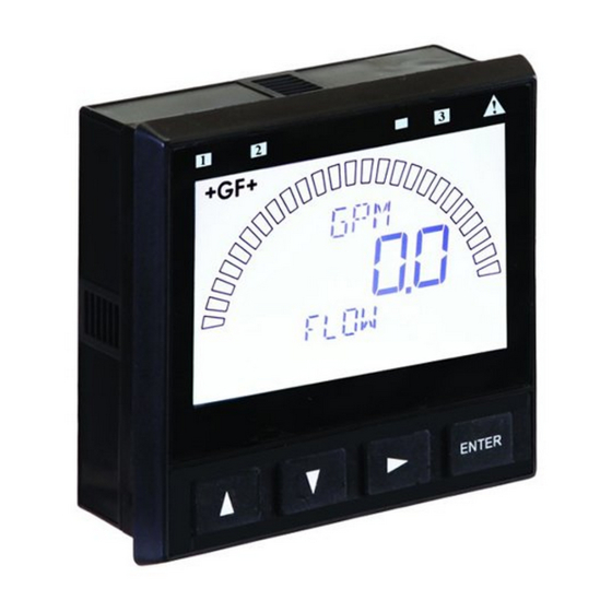
Signet 9900 Transmitter
*3-9900.090*
3-9900.090 Rev. G 02/17
Panel Mount
Field Mount
•
•
•
•
•
•
Quick Start
Look for the
Quick Start
icon to quickly
set up your
new 9900.
Description
The 9900 Transmitter, a member of Signet's line of SmartPro
provides a single-channel interface for all Flow, pH/ORP, Conductivity/Resistivity,
Salinity, Pressure, Temperature, Level, Dissolved Oxygen, Turbidity, Batch and
other applications.
The 9900 is available in either Panel or Field Mount. Both versions run on
10.8 to 35.2 VDC power (24 VDC nominal), and can power certain sensors on
loop power (see NOTE on page 11).
The 9900 Transmitter, also allows third-party 4 to 20 mA signals to be used as an
input (optional Signet 8058 i-Go
Compatibility
The 9900 is compatible with all GF Signet
products listed in the column to the right.
● pH and ORP electrodes require the
Signet 2750/2751 DryLoc
Electronics (sold separately).
● Conductivity/Resistivity or Salinity
English
measurement requires either the optional
Deutsch
Direct Conductivity/Resistivity Module
Français
(part number 3-9900.394) or the Signet
Español
2850 Conductivity/Resistivity Sensor
Italiano
Electronics (sold separately).
中文
NOTE: If using the 2850, use the one-
channel Digital (S
channel model 3-2850-63 may be used
with only one channel connected. Do
not use with both channels connected.
The 4 to 20 mA models 3-2850-52 and
3-2850-62 are incompatible with the 9900.
● Turbidity measurement using Signet 4150
or Dissolved Oxygen measurement using
Signet 2610-31 requires Signet 8058 i-Go
Signal Converter (sold separately).
Operating Instructions
Your new Signet 9900 Transmitter needs to be calibrated and the
sensor needs to be initialized prior to use. The following steps
outline the recommended procedure to start up a new system.
1. Module Installation (page 3)
2. Installation (page 7)
3. Wiring (page 8)
4. Sensor Wiring (page 11)
5. Power Wiring (page 17)
6. Relay and Open Collector Wiring (page 18)
7. Relay Functions (page 19)
8. Operation (page 23)
9. Menu System (page 25)
Signal Converter required, sold separately).
®
®
Sensor
L) models. The two-
3
English
instruments,
®
Flow
515*/8510*, 525*, 2000,
2100, 2507, 2536*/8512*,
2537, 2540*, 2551, 2552
pH/ORP
2724-2726 with 2750*/2751
2734-2736 with 2750*/2751
2756-WTx–2757-WTx with
3719 and 2750*/2751
2764-2767 with 2750*/2751
2774-2777 with 2750*/2751
Conductivity/Resistivity, Salinity
2819-2823 with
2850 or Cond/Res Module
2839-2842 with
2850 or Cond/Res Module
Level, Temperature, Pressure
2250*, 2350*, 2450*
Turbidity
4150 requires 8058
Dissolved Oxygen
2610-41 direct to 9900
2610-31 requires 8058
* Can be run on Loop Power
(see NOTE on page 11)
Advertisement
Table of Contents

Related Manuals for Signet 9900


Summary of Contents for Signet 9900
- Page 1 10.8 to 35.2 VDC power (24 VDC nominal), and can power certain sensors on loop power (see NOTE on page 11). The 9900 Transmitter, also allows third-party 4 to 20 mA signals to be used as an input (optional Signet 8058 i-Go Signal Converter required, sold separately).
-
Page 2: Table Of Contents
Relay and Open Collector Outputs ........19 Product Registration Operation ...............23 Menu System ..............25 Thank you for purchasing the Signet line of Georg System Setup Menu ..........25 Fischer measurement products. Common Menus .............27 If you would like to register your product(s), you can now LOOP Menu .............27... -
Page 3: Dimensions
Only) Module 91.44 mm (3.60 in.) If the 9900 Base Unit will be mounted in a panel, the 54.10 mm plug-in modules may be installed either before or after (2.13 in.) the base unit is mounted. If the 9900 Base Unit will be mounted using the wall mount accessory kit (3-9900.392),... -
Page 4: Plug-In Modules
In addition to the standard programmable Open Collector output in the base unit, the Panel Mount version of the 9900 has a slot for an optional Relay Module, which adds two programmable dry-contact relays. The Open Collector output in the base unit uses the Relay 1 setting in the menus. -
Page 5: Direct Conductivity/Resistivity Module
● 2839 - 2842 sensors come with a cell constant certifi cate to improve the accuracy of the sensor measurements (see page 38). Signet Conductivity Module cannot operate when using loop power and requires an external DC power supply to be used with the 9900 Transmitter (see Power Wiring, pg. 17). Black White... -
Page 6: Batch Module
● 4 to 20 mA Output Module can be powered using Loop Power or DC Power in the 9900 base unit. ● Independent settings for the loop currents of the Output Module and 9900 base unit (Error, Loop Adjustments, etc.). -
Page 7: Installation
Field Mount Installation Field mounting requires a separate mounting kit. The 3-8050 Universal Mount Kit, the 3-8051 or 3-8052 Integral Mount Kits, and the 3-9900.396 Angle Adjustment Adapter Kit enable the transmitter to be installed virtually anywhere. Detailed instructions for fi eld installation options are included with the 3-8050, 3-8051 and 3-8052 adapter kits (see Ordering Information section). -
Page 8: Wiring
For Field Mount installations, refer to the wiring diagram inside the Field All wiring connections to the 9900 are made via removable terminals. Mount housing. In general: ● The Power, Loop and Open Collector plugs and the Relay Module plug accept 12 to 28 AWG wire. -
Page 9: Signal Type: Frequency
515/8510 self-powered (515/8510 and 525), or powered by an external source. ● The input terminals on the 9900 carry frequency data signals from the sensor. 2000 ● Do not route sensor or output cables in conduit containing AC power wiring. -
Page 10: Signal Type: 4 To 20 Ma
Signal Type: 4 to 20 mA When connecting a non-Signet sensor to the 9900, the sensor’s 4 to 20 mA signal must be converted to Digital (S L). The 8058 i-Go Signal Converter accepts any 4 to 20 mA signal... -
Page 11: Sensor Wiring
If using both an H COMM Module and pH sensor, Connect power and open DC power is required. collector wires here as shown on pages 17 and 18. 9900 Generation Freq Digital (S Run on Sensor model Output Output... - Page 12 Sensor Wiring NOTE: Loop Power cannot be used to power Signet models 2000, 2100, 2507, 2537, 2551 or 2552 Flow sensors. Wiring for: Technical Notes: 515/8510 2536/8512 2540 • See corresponding product manuals for maximum cable FLOW Frequency length. • Maintain cable shield through cable splice.
- Page 13 • Either Frequency or Digital (S L) may be used. the 2551 & 2552 is supplied • Signet recommends confi guring these sensors with the Digital (S L) output by the 9900. No additional because it is more accurate and will also display reverse fl ow (negative numbers).
- Page 14 9900, the 2850 must be set Display Magmeter for the custom cell constant or the actual probe cell constant NOTE: The 2850 has no SHIELD wire. and the 9900 set for a 1.0 cell constant. Wiring for: 9900 S L Inputs...
- Page 15 Technical Notes: 9900 Power Inputs 9900 S L Inputs • 3-2610-31 Dissolved Oxygen PWR+ Sensor can be connected PWR– to the 9900 only via a LOOP+ 3-8058-1 or 3-8058-2 i-Go LOOP– Signal Converter. • Program the 9900 for the V– BLACK...
- Page 16 TB3 as shown in the fi gure. ALARM2 ALARM1 24 VDC – SHLD Refer to the latest revision of 4-20mA/ the Signet 4150 Turbidimeter RS-485 Manual (3-4150.090) for further information. SHLD ISL 1 Input 4-20 mA Black Technical Notes: Shield •...
-
Page 17: Power Wiring
Power Wiring CAUTION! DO NOT connect your 9900 to AC power. The 9900 MUST be powered by 10.8 to 35.2 VDC ONLY. Stand-alone application, no current loop used ProcessPro 9900 (for reference only) Transmitter 9900 Terminals Terminals Black Power –... -
Page 18: Relay And Open Collector Wiring
Most indicating instruments or control system inputs require a signal voltage of 0 to 5 V (TTL or CMOS logic levels) or 0 to 24 V. Therefore, the 9900 Open Collector output circuits must be equipped with a pull-up or pull-down resistor (not supplied), and a quality regulated 5 to 24 V (depending on the application) power supply (not supplied) is recommended to function properly. -
Page 19: Relay Functions
Open Collector turned “on” or “off” when the criteria for the activation of this output are met. If the 9900 is set to operate in RELAY LOW mode, when the user-defi ned condition for the activation is met (e.g. exceeding an alarm limit) the Open Collector switch is turned “on.”... - Page 20 TEST is performed. The timer will restart if the condition still exists. CAUTION! If power is lost to the 9900 Transmitter during a cycle, the Cycle Time will reset. If the condition still exists after power is restored, the relay will be energized for the complete Cycle Time.
- Page 21 In the example: • The output will be 0 pulses/min. when value is less than 5. • The output will be 50 pulses/min. when value is 7.5. • The output will be 100 pulses/min. when value is greater than 10. 9900 Transmitter...
- Page 22 OFF. Relay pulse width is the time the relay is ON. The 9900 must be programmed with the relay period, and with the low and high setpoints. NOTE: The PWM mode is not used for Pressure applications.
-
Page 23: Operation
UP, DOWN keys Scroll through Menu options or adjust values during editing Press both together to exit a menu or escape without saving RIGHT key Select item or character to edit ENTER key ENTER Access menus Save changes 9900 Transmitter... - Page 24 ENTER Edit System Setup: Menu Navigation This basic operating procedure repeats throughout the 9900 program: 1. Press ENTER for 3 seconds to enter MENU mode. 2. Press ► to move to the desired menu then press ENTER to select it. (Password may be required.) 3.
-
Page 25: Menu System
After installation and wiring is completed, apply power to the 9900. When the 9900 is fi rst powered on, it will attempt to determine the sensor type connected when ENTER is pressed (unit will display LOOKING FOR). - Page 26 ● STD The standard (STD) password is ▲▲▲▼, pressed in sequence. This password is designed to protect the 9900 from unintentional changes. It is best suited for systems where a group of people need to be able to change settings.
-
Page 27: Common Menus
Adjustment limits: from 3.80 mA minimum to 5.00 mA maximum. Default = 4.00 mA. (ALL) Allows fi ne-tuning to compensate for errors in other equipment connected to the 9900. Adjust the minimum and maximum current output. The display value represents the precise current output. -
Page 28: Relay Menu
Set minimum value for pulse width modulation. (ALL except PRESSURE and FLOW) (Shown only if PWM mode) Set maximum value for pulse width modulation. NOTE: Defaults for most relay functions are dependent upon sensor type and are not listed here. 9900 Transmitter... - Page 29 Cyc High Prop Pulse Vol Pulse Total Error * In USP Relay Mode in Conductivity, Relay Source must be set to COND, TEMP COMP must be set to NONE and Unit Of Measure must be set to μS. 9900 Transmitter...
-
Page 30: Option Menu
(ALL) Enter 13-character string, if desired. Default = Blank. Enables Remote Setup to confi gure the 9900 via a computer and the optional 0252 Confi guration tool. Press ► and select YES to enable. REMOTE SETUP flashes when mode is enabled. -
Page 31: Sensor-Specifi C Menus
Sets the volume of each count of the Totalizer as a multiple of the volume unit of the K-Factor. Min: 0.0001, max 999999. Cannot be zero. Default = 1.0000. Select to calibrate using Rate method (see Appendix). Select to calibrate using Volume method (see Appendix). Enter date of calibration (mm-dd-yyyy) and initials of calibrator (ii). 9900 Transmitter... - Page 32 Select Low, Med, High, OFF. (See discussion in Appendix.) Default = OFF. The Sensitivity setting determines how the 9900 responds to sudden changes in the fl ow rate. The value is expressed in units of measurement. If the setting is exceeded, it "overrides" the Averaging function breifl y to allow for the actual change in fl...
- Page 33 Displays the millivolt input from the electrode. Use this display to determine the relative condition of your electrode during periodic calibration. (7 pH buffer = 0 mV, ± 50 mV) (2751 preamp only, 9900 Generation IV or greater) Displays last AUTOMATED or MANUAL GLASS IMPEDANCE measurement.
- Page 34 CAL Menu Select AT SENSOR to perform calibration using the Signet 2750/2751 sensor electronics. Select AT INSTRUMENT to perform calibration at the 9900 via EasyCal or manual calibration. (See pH Calibration procedures in the Appendix.) Default = AT INSTRUMENT. YES prevents relays from activating while making adjustments, and relays in PULSE mode will suspend pulsing.
-
Page 35: Orp
Displays the millivolt input from the electrode. Use this display to determine the relative condition of your electrode during periodic calibration. (2751 preamp with memory chip enabled sensors only, 9900 Generation IV or greater) Press ► to access sensor data stored on sensor memory chip. - Page 36 CAL Menu Select AT SENSOR to perform calibration using the Signet 2750/2751 sensor electronics. Select AT INSTRUMENT to perform calibration at the 9900 via EasyCal or manual calibration. (See ORP Calibration procedures in the Appendix.). Default = AT INSTRUMENT. YES prevents relays from activating while making adjustments, and relays in PULSE mode will suspend pulsing.
-
Page 37: Conductivity/Resistivity
If bad cal, returns “ERR TOO LARGE TO CALIBRATE”. Resets Conductivity calibration. After pressing ►, select YES/NO. Resets Temperature calibration. After pressing ►, select YES/NO. Enter date of calibration (mm-dd-yyyy) and initials of calibrator (II). 9900 Transmitter... - Page 38 NOTE: If using a 2850 Conductivity/Resistivity Sensor Electronics in conjunction with your 9900, the 2850 must be set for the custom cell constant or the actual probe cell constant and the 9900 set for a 1.0 cell constant. 9900 Transmitter...
-
Page 39: Pressure
Enter units of pressure measurement. Select PSI, BAR, or KPa. Default = PSI. Dampens display, output and relay response rates. Select: Low, Med, High, OFF (see discussion in Appendix.) Default = OFF. Signet strongly recommends leaving averaging OFF for pH and pressure measurements (see discussion in Appendix). 9900 Transmitter... -
Page 40: Level/Volume
Shows SET LEVEL on bottom line. When user presses any key, the live value is frozen and the user edits that value. Returns either GOOD CAL or LEVEL OFFSET TOO LARGE. Resets calibration to factory default. After pressing ►, select YES/NO. Enter date of calibration (mm-dd-yyyy) and initials of calibrator (ii). 9900 Transmitter... - Page 41 (To defi ne a custom tank shape, see Appendix page 52, Defi ning a Custom Tank.) Default = VERT CYLINDER. If VERT CYLINDER or HORIZ CYLINDER is selected, enter the diameter of the cylinder. Displayed in units of measure chosen in LEVEL UNITS. Default = 2.0000 9900 Transmitter...
-
Page 42: Temperature
INPUT Menu Enter string up to 13 characters (optional). Default = “TEMPERATURE”. Select °C or °F. Default = °C. Dampens display, output and relay response rates. Select Low, Med, High, OFF. (See discussion in Appendix.) Default = OFF. 9900 Transmitter... -
Page 43: To 20 Ma
SLOPE. Else, assign the min value to the SLOPE. The slope and standard values must be at least 0.1 units apart. Resets Standard and Slope calibration to factory settings. After pressing ►, select YES/NO. Enter date of calibration (mm-dd-yyyy) and initials of calibrator (ii). 9900 Transmitter... - Page 44 Select Low, Med, High, OFF. (See discussion in Appendix.) Default = OFF. To program the 9900 for Dissolved Oxygen measurement using the 3-2610-31 sensor: From the 4 to 20 mA View Mode display: Press and hold the ENTER key for 2 seconds.
-
Page 45: Salinity
Provides a maximum 20 °C offset to match to a known standard (external reference). Resets Salinity calibration to factory settings. After pressing ►, select YES/NO. Resets Temperature calibration to factory settings. After pressing ►, select YES/NO. Enter date of calibration (mm-dd-yyyy) and initials of calibrator (II). 9900 Transmitter... - Page 46 Select temperature compensation (NONE, LINEAR). Default = LINEAR. For LINEAR temperature compensation, select a % per ºC slope. Maximum slope setting is 9.99 % per ºC. (If Temperature Compensation setting is NONE, this item will not be displayed.) 9900 Transmitter...
-
Page 47: Dissolved Oxygen
Press ENTER to save value and establish an optional second calibration point. This option is only available immediately after a successful 100% Solution calibration. Resets Dissolved Oxygen calibration to factory settings. After pressing ►, select YES/NO. Enter date of calibration (mm-dd-yyyy) and initials of calibrator (II). 9900 Transmitter... - Page 48 Manually set Barometric value to match application altitude above or below sea level (506.62 - 1114.7 mBAR). 1013.2 Default = 1013.2 (sea level) BAROMETRIC Select °C or °F. Default = °C. Dampens display, output and relay response rates. Select Low, Med, High, OFF. (See discussion in Appendix.) Default = OFF. 9900 Transmitter...
-
Page 49: Troubleshooting
K-Factor Out Of Range K-Factors cannot be set to 0 Enter K-Factor from 0.0001 to 99999 9900 operating on loop power Connect 9900 to 10.8 to 35.2 VDC power. Backlight turned OFF Backlight inoperative Set BACKLIGHT to LOW, HIGH or AUTO (NOTE: Backlight can turn off in OPTION menu. - Page 50 9900 cannot "talk" to sensor Level, Temp, 4-20 mA, • Install or replace sensor Sal, Batch, DO) Check Preamp 9900 cannot "talk" to the preamp Check wiring or replace preamp Warning LED lit Look for error message Correct error condition...
-
Page 51: Appendix
If ADJUST 4 mA or ADJUST 20 mA is used, the mA value can be affected. To prevent any problems the adjust function should only be used to get exactly 4.0 and 20.0 at the PLC. The 9900 is accurate and the adjust functions are only needed to compensate for an offset due to noise or a not-so-accurate PLC input card. -
Page 52: Custom Measurements
The point in the vessel where you want the 9900 to display zero (0 ft, 0 gal. etc.). • If Z is located below the fl uid surface, the 9900 For most vessels, the zero reference point (Z) may be will display a positive level measurement. - Page 53 Custom point #8 1000 gal. Custom point #7 700 gal. Custom point #6 380 gal. Custom point #5 250 gal. Custom point #4 160 gal. Custom point #3 118 gal. Custom point #2 45 gal. Custom point #1 0 gal. 9900 Transmitter...
- Page 54 3. Pour another 10 gallons into the tank. POINT 2 LEVEL will indicate actual tank level. 4. In POINT 2 VOL, enter 10. 5. Pour the fi nal 5 gallons into the tank. POINT 3 LEVEL will indicate actual tank level. 6. In POINT 3 VOL, enter 5. 9900 Transmitter...
- Page 55 Level, Volume, and Mass Measurement Level = P ÷ (SG × D) where P = Pressure The 9900 can automatically perform SG = Specifi c Gravity of fl uid level, volume and mass calculations: = Density of water ● Pressure-to-level ●...
-
Page 56: Calibration Procedures - Ph
Mode in 10 minutes 10 ....–177 11 ....–237 12 ....–296 NOTE: The solutions can be used for calibrating more than one sensor; however, the solution must remain free of debris and must not be diluted by rinse water from previous calibrations. 9900 Transmitter... - Page 57 0 to 14 pH (buffers of pH 4.01, 7, or 10 are recommended, but use a buffer close to your own process value.) Single-point calibration sets To Calibrate: To Change Reading: STANDARD only; Signet recommends a two-point calibration to set SLOPE in addition to STANDARD. Quick Manual...
-
Page 58: Calibration Procedure - Orp
30 seconds • 476mV (Light's Solution) Press ENTER. After 30 seconds, To exit menus and return to 9900 will recognize Display returns to VIEW Mode in 10 minutes current buffer ±80 mV. buttons at the same time. Press ENTER to accept mV value. - Page 59 (System calibration is possible with two known ORP solutions, but use a buffer close to your own process value). Single-point calibration To Calibrate: To Change Reading: sets STANDARD only; Signet recommends a two-point calibration to set SLOPE in addition to STANDARD. Quick Manual Calibration Procedures:...
-
Page 60: Calibration Procedure - Conductivity/Resistivity
AutoCal is a single-point calibration system. During this procedure, if the measured the CALIBRATE menu. value is within ± 10% of any of the test values listed below, the 9900 will automatically Resistivity displayed recognize the test value and calibrate the output to that value. -
Page 61: Calibration Procedure - Flow
(If the calculated K-Factor is less than 0.0001 or greater than 999999 (out of range at either extreme), the 9900 displays "ERROR NEW KF OUT OF RANGE" and returns to RATE CAL. If fl ow is too low to accurately calibrate, the 9900 displays "ERROR FLOW RATE TOO LOW and returns to RATE CAL. -
Page 62: Calibration Error Messages
Set pH Slope or Standard (pg. 34 & 57) (possibly due to memory failure in Set ORP Slope or Standard (pg. 36 & 59) (2751 pH/ORP only) sensor or preamp) Reset pH CAL (pg. 34) Reset ORP CAL (pg. 36) 9900 Transmitter... -
Page 63: Usp Limits
USP setpoints are defi ned as a percentage below the USP limit, so a USP alarm 20 to < 25 is always a HIGH alarm. The 9900 can be set to warn you if the conductivity approaches within a set percentage of the USP limit. -
Page 64: H Comm Module Overview
Features available in the 9900 Transmitter with H COMM Module installed: • Adjust 4 mA: Allows fi ne-tuning to compensate for errors in other equipment connected to the 9900. Adjust the minimum and maximum current output. -
Page 65: H Comm Module Installation
H COMM Module Installation If the 9900 Base Unit will be mounted in a panel, plug-in modules may be installed either before or after the base unit is mounted. If the 9900 Base Unit will be mounted using the accessory wall mount kit , install plug-in modules fi... - Page 66 Up to four 9900 Transmitters can be connected in Multi-Drop mode using the H COMM Module. To ensure proper operation in Multi-Drop mode, confi gure each 9900 Transmitter with its own poll address using a confi guration tool (laptop or hand-held device).
-
Page 67: H Comm Module Operation
Changes to Units of Measure in Transmitter HART devices can be used to change the units of measure in a 9900 Transmitter. After an update, you must cycle power to the 9900 Transmitter (remove power for 5 seconds, then restore power). In a fl ow system, the units update automatically and it is not necessary to cycle power to the 9900 Transmitter. -
Page 68: Hart Commands
Reads transmitter serial number, unit code, upper and lower limits and minimum span for primary variable. Command 15 – Read Device Information Returns the alarm selection code, transfer function code, upper and lower range values, write protect code and unit code. 9900 Transmitter... -
Page 69: Unit Codes
Command 46 – Trim Loop Current Gain The 9900 will trim the gain of the loop current to match the loop current value sent to it. This is typically performed at 20.00 milliamperes to optimize calibration. Command 54 – Read Device Variable Information Returns serial number, limits, damping value and minimum span for a selected device variable. -
Page 70: Specifi Cations
DC (preferred) ....24 VDC; input range: Terminal Blocks 10.8 to 35.2 VDC regulated Pluggable screw type: use minimum 105 °C rated wire 9900 w/o Relay Module ..200 mA * Torque ratings 9900 w/ Relay Module ..300 mA * Cond/Res, Open Collector, *The current draw of the other modules and the sensors are minimal Power/Loop..0.33 Nm (3.0 lb-in.) -
Page 71: Maintenance
L) output from the @ 24 VDC 2750/2751 pH/ORP Sensor Electronics Resolution....6 μA or better ● Raw Conductivity/Resistivity input directly from Signet Temp. Drift ....± 1 μA per °C Conductivity/Resistivity electrodes via Direct Conductivity/ Pwr Sply Rejection ..± 1 μA per V... -
Page 72: Ordering Information
Angle Adjustment Adapter Kit (for Field Mounting) Georg Fischer Signet LLC, 3401 Aero Jet Avenue, El Monte, CA 91731-2882 U.S.A. • Tel. (626) 571-2770 • Fax (626) 573-2057 For Worldwide Sales and Service, visit our website: www.gfsignet.com • or call (in the U.S.): (800) 854-4090 For the most up-to-date information, please refer to our website at www.gfsignet.com...
Need help?
Do you have a question about the 9900 and is the answer not in the manual?
Questions and answers