Advertisement
Quick Links
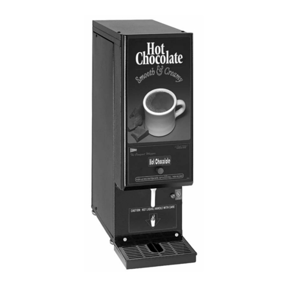
Compact Powdered Beverage Dispenser
Model GB3CP
Safety Information..................2
Installation...............................3
Operation ................................6
Cleaning...................................7
Thank you for purchasing this quality powdered beverage dispenser. For your safety and the safety of others,
read all warnings and the operator manual before installing or using the product. Properly instruct all operators.
Keep training records. For future reference, record serial number here:
Grindmaster-Cecilware
4003 Collins Lane, Louisville, KY 40245 USA
Phone: 502.425.4776 Toll Free: 800.695.4500
Fax: 502.425.4664
Web: gmcw.com Email: info@gmcw.com
©2016 Grindmaster-Cecilware
Printed in USA
GB Models 1CP, 2CP, 3CP
Model GB1HC-CP
Table of Contents
Maintenance ...........................8
Troubleshooting Guide.........11
Parts Diagram and List..........12
Wiring Diagrams ...................15
Operator Manual
Grindmaster-Cecilware provides the industry's
BEST warranty. Visit gmcw.com for warranty
terms and conditions.
Model GB2CP
0516 Form # CW-318-01
Part # 390-00015
Advertisement

Related Manuals for Cecilware 1CP


Summary of Contents for Cecilware 1CP
-
Page 1: Table Of Contents
Operator Manual Compact Powdered Beverage Dispenser GB Models 1CP, 2CP, 3CP Model GB3CP Model GB1HC-CP Model GB2CP Table of Contents Safety Information....2 Maintenance ......8 Installation.......3 Troubleshooting Guide..11 Operation ........6 Parts Diagram and List..12 Cleaning........7 Wiring Diagrams ....15 Thank you for purchasing this quality powdered beverage dispenser. For your safety and the safety of others, read all warnings and the operator manual before installing or using the product. -
Page 2: Safety Information
To avoid damaging unit, turn on power and wait for tank to fill with water before turning on heater. Observe machine voltage configuration. Do not apply improper voltage to machine or damage to machine will occur. Do not use extension cord. Cecilware GB Series ®... -
Page 3: Installation
In addition: damage, contact the shipper not Grindmaster- 1. A quick disconnect water connection or enough Cecilware. extra coiled tubing (at least 2x the depth of the After the machine has been unpacked and placed on a unit) so that the machine can be moved for counter, pull out the stainless steel drip tray. - Page 4 Note: Refer to following illustration for description and location of COMPONENTS and CONTROLS. Heater Switch located in rear Hoppers Mixing Chamber Rinse Switch Hoppers Pilot Light for Heater Spout Power Switch Drip Tray Rear of machine Cecilware GB Series ®...
- Page 5 5. WATER LEVEL CONTROLS: Under normal If you need help, call Grindmaster-Cecilware Technical conditions and operation, the water level in the Service Department, (502) 425-4776 or (800) 695-4500 tank should not drop more than 1/2" (13 cm) (USA &...
-
Page 6: Operation
Mixing Chamber, as shown. TRIANGULAR RIB 3. To DECREASE the water temperature - simply turn the Thermostat Knob one notch counter-clockwise to the next lower dial setting. CORRECT WATER LEVEL FOR MAX FLOW RATE. MIXING CHAMBER Cecilware GB Series ®... -
Page 7: Cleaning
Let all sanitized parts drain and air dry. DO NOT MIX BOWL SOCKET DISPENSE CUP WIPE THEM DRY. MIXING CHAMBER BASE MOUNT GROMMET SLINGER DISC WHIPPER CHAMBER TWIST TO REMOVE MOUNTING BASE 'O'-RING #125 EXTENSION TUBE WHIPPER BLADE GB Series Cecilware ®... -
Page 8: Maintenance
Clean out vent motor, trough, and tubing. • Repair Kit M491QL. • Lift up black tabs, remove trough drawer. • Clean and replace trough drawer. • Remove hose assembly from the motor. • Clean out and replace hose. WATER FLOW ADJUSTMENT Cecilware GB Series ®... - Page 9 3. Tuck clear plastic panel inside bracket at top. 4. Be sure to tuck clear panel under bracket before sliding frame assembly inside door. 5. The longer metal tab side goes in the front. TL LLLLLLL LLL GB Series Cecilware ®...
- Page 10 3. If the water does not flow in when the cord is plugged into an electrical outlet, the Solenoid coil may be damaged, opened or the valve may have an obstruction preventing the water from flowing in. Clean or replace it. HOSE NUT ASSY WATER INLET VALVE Cecilware GB Series ®...
-
Page 11: Troubleshooting Guide
Heater is burned out or defective. Replace the Heater. If you still need help, call Grindmaster-Cecilware Technical Service Department, (502) 425-4776 or (800) 695-4500 (USA & Canada only) (Monday through Friday 8 AM - 6 PM EST). Please have the model and serial number ready so that accurate information can be given. -
Page 12: Parts Diagram And List
Parts Diagram and List External Components Assembly Cecilware GB Series ®... - Page 13 HEATER SWITCH IN BACK OF UNIT NOT SHOWN L069AL Power Switch in Hopper Compartment L584AL Dispense Switch, GB1 L584AL Dispense Switch, GB2 L735AL Dispense Switch, GB3 L069AL Rinse Switch, GB1 L584AL Rinse Switch, GB2 L584AL Rinse Switch, GB3 GB Series Cecilware ®...
- Page 14 359-00098 WATER INLET CONNECTOR 120V 60HZ UNITS MANUFACTURED PRIOR TO JUNE 2015 USE THE FOLLOWING COMPONENTS: THERMOSTAT & PROBE L532AL THERMOSTAT KNOB M008AL UNITS MANUFACTURED PRIOR TO 2008 USE THE FOLLOWING COMPONENTS: THERMOSTAT & PROBE L681AL Cecilware GB Series ®...
-
Page 15: Wiring Diagrams
Wiring Diagrams GB1CP - WATER LEVEL CONTROL - GB Series Cecilware ®... - Page 16 Wiring Diagrams (continued) GB2CP RELAY - WATER LEVEL CONTROL - Cecilware GB Series ®...
- Page 17 Wiring Diagrams (continued) GB3CP GB Series Cecilware ®...
- Page 18 Cecilware GB Series ®...
- Page 19 GB Series Cecilware ®...
- Page 20 Grindmaster-Cecilware 4003 Collins Lane, Louisville, KY 40245 USA Phone: 502.425.4776 Toll Free: 800.695.4500 Fax: 502.425.4664 Web: gmcw.com Email: info@gmcw.com 0516 Form # CW-318-01 ©2016 Grindmaster-Cecilware Part # 390-00015 Printed in USA...
Need help?
Do you have a question about the 1CP and is the answer not in the manual?
Questions and answers