Eaton S611 User Manual
Hide thumbs
Also See for S611:
- Quick start installation manual (17 pages) ,
- Installation leaflet (2 pages) ,
- Installation leaflet (4 pages)

Related Manuals for Eaton S611


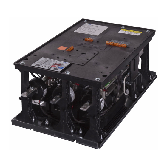
Summary of Contents for Eaton S611
- Page 1 S611 Soft Starter User Manual Effective May 2012 Supersedes August 2011 www.comoso.com...
- Page 2 www.comoso.com...
- Page 3 OBLIGATION OF EATON. THE CONTENTS OF THIS DOCUMENT SHALL NOT BECOME PART OF OR MODIFY ANY CONTRACT BETWEEN THE PARTIES. In no event will Eaton be responsible to the purchaser or user in contract, in tort (including negligence), strict liability or other-wise for any special, indirect, incidental or consequential...
- Page 4 S611 Soft Starter Support Services The goal of Eaton is to ensure your greatest possible satisfaction with the operation of our products. We are dedicated to providing fast, friendly, and accurate assistance. That is why we offer you so many ways to get the support you need. Whether it’s by phone, fax, or e-mail, you can access Eaton’s support information 24 hours a day, seven days a week.
-
Page 5: Table Of Contents
Servicing the S611 ........ - Page 6 Overload Trip Curves ..........S611 Motor Protection Parameters ........
- Page 7 S611 Soft Starter ........
- Page 8 S611 Terminal Block Control Wiring ........
- Page 9 S611 Fault Codes ........
-
Page 10: Definitions And Symbols
Do not apply a disconnect device on the output of the WARNING S611 soft starter unless a means to turn off the soft starter when disconnect switch is open is used. Opening Indicates a potentially hazardous situation which, if not disconnect while the soft starter is operating may cause avoided, can result in serious injury or death. - Page 11 WARNING Only apply 24 Vdc to the communication module fieldbus connection. Use of any other voltage may result in personal injury, property damage and damage to the module. S611 Soft Starter MN03902011E—May 2012 www.eaton.com www.comoso.com...
- Page 12 S611 Soft Starter S611 Soft Starter MN03902011E—May 2012 www.eaton.com www.comoso.com...
-
Page 13: Introduction
NEMA ICS 1, ICS 2 and ICS 5, UL 508, IEC 60947-4-2, and at comms port B adds excessive height to the S611, the CSA 22.2/14-05. adapter may be mounted to the side of the S611 and wired General Appearance Notes S611 Soft Starter... -
Page 14: Standards And Certifications
Meets requirements IEC 61000-4-8 Voltage dips interrupt 30% dip at 10 ms control power 60% dip at 100 ms 100% dip at 5s Emissions Radiated EN 55011, Class A Conducted EN 55011, Class A S611 Soft Starter MN03902011E—May 2012 www.eaton.com www.comoso.com... -
Page 15: Technical Data And Specifications
20.83 (529) 11.58 (294) 8.37 (213) S611D242XXX 86 (39) 31.15 (791) 17.56 (446) 9.54 (242) S611E302XXX 86 (39) 31.15 (791) 17.56 (446) 9.54 (242) S611E361XXX 102 (46) 31.15 (791) 17.56 (446) 9.54 (242) S611F414XXX S611 Soft Starter MN03902011E—May 2012 www.eaton.com www.comoso.com... -
Page 16: Short-Circuit Ratings-Component
Note: Suitable for use on a circuit capable of delivering not more than 100,000 rms symmetrical amperes, 600 volts maximum when protected by Class RK5 fuses or a circuit breaker having an interrupting rating not less than 65,000 rms symmetrical amperes, 480 volts maximum. S611 Soft Starter MN03902011E—May 2012 www.eaton.com www.comoso.com... -
Page 17: Receipt/Unpacking
The ambient temperature is –40° to 185°F (–40° to 85°C) ● carton damage to the carrier prior to accepting the delivery. Have this information noted on the freight bill. Eaton is not The relative humidity is 0–95%, noncondensing ● responsible for damage incurred in shipping. -
Page 18: Installation
For ease of installation, several slotted holes are provided on the muting plate for the S611. Slotted and/or round holes may be used as long as two holes top and two holes bottom (four total) are used, minimum. -
Page 19: C And D Frame
8 Places E and F Frame 9.50 5.00 6.10 5.00 (241.3) (127.0) (155.0) (127.0) 6.81 (172.9) 29.69 (754.1) 22.13 (562.0) 17.56 (446.1) Ø 0.53 (13.5) 5.00 6.10 5.00 8 Places (127.0) (155.0) (127.0) S611 Soft Starter MN03902011E—May 2012 www.eaton.com www.comoso.com... -
Page 20: Current Transformer Installation
The S611 is wired only in an inline connected configuration. mechanical lug installation: By factory default, the S611 is to be connected with an ABC The lug is mounted under the soft starter bus bar as phase rotation on the incoming power wiring. If the motor ●... -
Page 21: Line Connected Soft Starter Power Wiring Diagram
Power terminal wire connectors are not shipped with the product. To maintain the agency certifications/listings, Eaton recommends using the wire connectors (lugs) in the table below. Customers may select lugs that are commercially available and suitable for use, from industry standard sources that meet the general specifications in the table below. -
Page 22: Control Wiring Inputs
Control Wiring Inputs Control wiring is connected to the S611 by terminal blocks located at the front of the unit. Using the wiring diagrams below and on Pages 12–14, and table on Page 11 as guides, connect the control wiring as required for your application. Failure to follow this caution may result in severe damage to the controller. -
Page 23: Terminal Block Wiring Capacity
Requirements 22–16 AWG (0.33–2.5 mm 3.5 lb-in (0.4 Nm) 14–12 AWG (4.0 mm 3.5 lb-in (0.4 Nm) Control Terminal Descriptions The S611 soft starter has the following control terminal block connections: S611 Terminal Block Control Wiring Name Terminal Function Connections... -
Page 24: Basic Connection Diagram For 120 Vac Three-Wire Pushbutton
Each diagram illustrates a typical wiring scheme for the options described. The additional components shown on the diagrams are not included, but may be purchased from Eaton. Mains power is not required to energize the control circuit of the S611. All protection and operation parameters may be adjusted using only control power. -
Page 25: Basic Connection Diagram For 120 Vac Two-Wire Pushbutton
See “Using Auxiliary Contacts” section if it is desired to use a relay instead of an indicating lamp for terminals 13, 14, 95, 96 and 98. If an isolation or reversing contactor is used upstream of the S611, Eaton recommends that the operator uses the level sensing option (default value) of the Start Control Parameter Code in the Advanced Parameters Menu. -
Page 26: Basic Connection Diagram For 120 Vac Network Control
See “Using Auxiliary Contacts” section if it is desired to use a relay instead of an indicating lamp for terminals 13, 14, 95, 96 and 98. If an isolation or reversing contactor is used upstream of the S611, Eaton recommends that the operator uses the level sensing option (default value) of the Start Control Parameter Code in the Advanced Parameters Menu. -
Page 27: Control Power Requirements
14 AWG (2.5 mm Connecting a New or Replacement User Interface Module (UI) 1200 The S611 uses the User Interface Module (UI) to change the 1200 configuration of operating parameters with a display to indicate values and fault codes. By entering parameter... -
Page 28: 120 Vac Control
(PLC), or in a 120 Vac control circuit. Fault If the S611 soft starter is subject to mechanical shock during operation, it is possible that these contacts may momentarily open, causing nuisance fault tripping of down stream Using a Supplemental Line Contactor devices. -
Page 29: Functional Description
There are four (4) terminal blocks and one (1) connector on three-phase induction motor in order to control the starting the face of the S611 soft starter that are used for control torque and provide a smooth starting characteristic. Within... -
Page 30: Starting/Stopping Options
It should be noted that a lightly loaded motor takes less torque, and thus lower voltage and time to accelerate to full speed. For this case the S611 will go into bypass before the ramp reaches full voltage. In other words, the S611 will go into bypass before the Soft Start Time has elapsed. -
Page 31: Current Limit
This mode is typically used when it is necessary to limit the maximum current during start-up due to line power limitations or other considerations. During a current limit start the S611 applies a constant voltage to the motor, resulting in limited current flowing through the motor’s windings. -
Page 32: Control Functions
Note: With level sensing control, if 120 Vac is lost or removed from the Permissive terminal at any time, When the S611 is in network control, it is ready to respond to the unit will initiate a stop in accordance with setup motor START control commands issued only through the parameter selections. - Page 33 If the Start control signal is momentary, means that the 120 Vac signal at the Start terminal must be then either edge or level sensing may be selected and S611 removed (if maintained) and reapplied after a fault trip has operation will be the same, as in either case only a occurred.
-
Page 34: S611 Operating Configuration
S611 Operating Configuration Introduction The S611 has a wide range of set points to enable coordinated motor and load protection. Commonly used set points are directly accessible through the user interface; advanced configuration of the device must be performed through the Advanced Config operation or over the network. -
Page 35: User Interface Components
Exit the Fault Log mode by pressing the Fault Log button Reset • Trip reset button—the indicated fault is cleared and the S611 returns to the “Ready” state Any active fault will prevent the S611 from being reset Discrete LEDs Status •... -
Page 36: Setup And Starting
The Permissive and Network inputs must be energized (120 Vac) to enable starting of the soft starter from the network. After an overload trip, the S611 soft starter cannot be restarted until the prescribed cool-down time has elapsed. Cycling control power does not reset the timer. If 120 Vac power is removed, the soft starter will remember the remaining time and will resume the cool-down timing when power is again reapplied. -
Page 37: Operating Parameters-Standard
Start. Review the Advanced Protection options of the S611 shown in Appendix B— Protection and select the appropriate ones for your application. -
Page 38: Operating Parameters-Pump Option
Phase loss Off, 1 Under voltage Off, 1 Over voltage Off, 101 Voltage imbalance Off, 1 Phase sequence — Off, ABC Note: Editing the Trip Class parameter to “OFF” will disable overload protection. S611 Soft Starter MN03902011E—May 2012 www.eaton.com www.comoso.com... -
Page 39: Fault Codes
For troubleshooting purpose trips are recorded, as they occur, in the S611’s fault log. Apply the mains voltage and verify that no fault is present. The S611 indicates most faults with a fault code in the alphanumeric display and by illuminating the corresponding mode and Protection/ Operation (P/O) LEDs. - Page 40 Soft Start Time at 1.25 times this time. For example, if it takes 10 seconds to accelerate the motor and go into bypass, set the Soft Start Time for 12.5 seconds. Adjust the Soft Stop Time for the desired stopping time. S611 Soft Starter MN03902011E—May 2012 www.eaton.com www.comoso.com...
-
Page 41: Troubleshooting
Define the Problem The S611 soft starter fails to respond in any way to a start command. Look at the front panel of the S611 soft starter and determine the state of the LEDs on the User Interface Module (UI). -
Page 42: Start Command Troubleshooting Flowchart
If the Start Control parameter is set to Edge, verify that the 120V start signal is transitioned from 0 Vac after a fault trip Network Determine if the S611 can be started locally from TB3 Verify that the 120V permissive signal is at the proper voltage... -
Page 43: S611 Stopped Or Faulted
Protection Fault LED or fault code and go to the S611 Fault Codes in Appendix G— • The S611 soft starter trips after the Stop command is Troubleshooting Guide to find the corrective action for received the fault code. -
Page 44: Local Control Troubleshooting Flow Chart
Check for fault, set Reset external device mode to Manual failures Fault Code repeats Unit trips, Verify Fault fault code condition does present not exist Correct fault condition Contact Eaton Support Contact Eaton Support S611 Soft Starter MN03902011E—May 2012 www.eaton.com www.comoso.com... -
Page 45: Parts And Service
Servicing the S611 S611 Printed Circuit Board (PCB) Replacement Disconnect power in accordance with federal, state, and local codes and remove the S611 from the enclosure or mounting panel. Note: Servicing the S611 while installed in an enclosure or mounted vertically on a panel is not recommended. -
Page 46: Pcb Connector Ids
The cable may also be removed after PCB is removed from the cover. Remove the 5 #1 Phillips self tapping screws—one in each corner, one in center. Remove PCB from cover assembly. S611 Soft Starter MN03902011E—May 2012 www.eaton.com www.comoso.com... -
Page 47: Contactor Connector
S611 Internal Bypass Contactor Replacement Disconnect power in accordance with federal, state, and local codes and remove the S611 from the enclosure or mounting panel. Note: Servicing the S611 while installed in an enclosure or mounted vertically on a panel is not recommended. -
Page 48: A-D Frame Contactor Assembly
Remove nuts securing contactor support assembly to baseplate. Lift contactor support assembly from the baseplate. Remove terminal plates from contactor(s). Remove the socket head cap screws and the contactor from the support assembly. S611 Soft Starter MN03902011E—May 2012 www.eaton.com www.comoso.com... -
Page 49: Optional Accessory Kits
User interface communication cable—3.28 ft (1m) 52–414A D77E-QPIP100 User interface communication cable—6.56 ft (2m) 52–414A D77E-QPIP200 User interface communication cable—9.84 ft (3m) 52–414A D77E-QPIP300 Lug kit—mechanical 52–77A S611-LUG-M01 99–125A S611-LUG-M02 156–242A S611-LUG-M03 302–414A S611-LUG-M04 S611 Soft Starter MN03902011E—May 2012 www.eaton.com www.comoso.com... -
Page 50: Replacement Parts
Control board assembly—302A pump S611-PCB-302P Control board assembly—361A pump S611-PCB-361P Control board assembly—414A pump S611-PCB-414P Frame A/B CT S611-CT-AB Frame C/D CT S611-CT-CD Frame E/F CT S611-CT-EF Contactor assembly—52–180A C25DNY172 Contactor assembly—242–414A C25DNY173 S611 Soft Starter MN03902011E—May 2012 www.eaton.com www.comoso.com... -
Page 51: Appendix A-Parameters
Start time Seconds — Initial torque — Stop time Seconds — Kick start time Seconds — Kick start torque — Auto reset mode — 0 = Manual 1 = Auto Advanced config — — S611 Soft Starter MN03902011E—May 2012 www.eaton.com www.comoso.com... -
Page 52: Operation Mode-Pump Option
Under load Off, 1 Phase loss Off, 1 Under voltage Off, 1 Over voltage Off, 101 Voltage imbalance Off, 1 Phase sequence — Off, ABC Note: Setting any parameter to OFF disables the protection. S611 Soft Starter MN03902011E—May 2012 www.eaton.com www.comoso.com... -
Page 53: Advanced Operation Mode
7 = Average pole temperature 8 = Pole temp A phase 9 = Pole temp B phase 10 = Pole temp C phase P.08 Configuration Reset 1 = Power cycle 2 = Restore factory default parameters S611 Soft Starter MN03902011E—May 2012 www.eaton.com www.comoso.com... - Page 54 Overload on Start Enable 0 = Disable 1 = Enable P.29 Command Register 0 = No action 1 = Clear motor run hours 2 = Clear motor start count 3 = Clear fault queue S611 Soft Starter MN03902011E—May 2012 www.eaton.com www.comoso.com...
-
Page 55: User Interface Monitoring
Status–Ready Down–( ) Total motor power X.XX if kW <10 Mode–Monitor XX.X if kW <100 Units–kW XXX if kW 100 Phase–AVG Status–Ready Down–( ) Motor thermal capacity/User 0–100 Mode–Monitor selected Units–TC Phase–None Status–Ready S611 Soft Starter MN03902011E—May 2012 www.eaton.com www.comoso.com... -
Page 56: Motor Protection/Basic Programming Set Points
Display Messages The following display messages may appear on the S611 User Interface Module (UIM) to indicate status. Display Messages Message Description Indicates that the top of the fault list has been reached Indicates that the bottom of the fault list has been reached The protection parameter is disabled. -
Page 57: Motor Protection/Advanced Programming Set Points
Operation LEDs (P/O LEDs). More advanced settings are available indirectly (through parameter codes) by selecting the Operation mode and the Advanced Config parameter. The following diagram outlines the procedure for editing the advanced set points of the S611. See table on Page 41 in Appendix A—Parameters for advanced parameters. -
Page 58: Fault Display
Fault Display The S611 indicates most faults with a fault code and by illuminating the corresponding mode and Protection/Operation (P/O) LEDs. In addition, the dedicated Fault LED will be illuminated when the device is faulted. Fault Display User Interface Fault... -
Page 59: Fault History
Fault History The S611 stores the last 10 fault codes in a queue stored in non-volatile memory. This fault queue can be traversed using the following sequence of button presses. Fault History Step 1: Press the Fault Log button when the Fault LED is lit. The display starts flashing, shows the last fault code, and illuminates the corresponding Protection/Operation LEDs as appropriate to identify the fault. -
Page 60: Entering Basic Operating Parameters
Step 4: Use the Up/Down buttons to adjust the parameter to the desired value. Step 5: Press the Edit/Save button. The display now stops flashing and shows the new parameter value that has been saved by the device. Edit/Save S611 Soft Starter MN03902011E—May 2012 www.eaton.com www.comoso.com... -
Page 61: Appendix B-Protection
Appendix B—Protection Thermal Overload The S611 soft starter features an electronic motor overload WARNING protection feature. This is intended to protect the motor and power wiring against overheating caused by excessive Setting the Overload Trip Class parameter to OFF current for extended periods of time. -
Page 62: Overload Trip Curves
Overload Trip Curves Overload Trip Curves 10000.0 115% Class 5 1000.0 Class 10 Class 20 Class 30 100.0 Class 30 Class 20 Class 10 Class 5 10.0 Percent FLA S611 Soft Starter MN03902011E—May 2012 www.eaton.com www.comoso.com... -
Page 63: S611 Motor Protection Parameters
Not user settable Motor Stall The S611 monitors the maximum rms value of the three-phase currents. The unit will trip with a motor stall fault if the stall fault is enabled and the maximum rms value exceeds the trip threshold setting when the start time setting expires. -
Page 64: Motor Jam Settings
23.0 seconds SCR Overcurrent The SCR overcurrent trip is only active if the stall fault trip is disabled. The S611 monitors the maximum rms value of the three-phase currents. The unit will trip with an SCR overcurrent fault if the stall fault is disabled and the maximum rms value exceeds three times the FLA setting when the start time setting expires. -
Page 65: Under Load Settings
Advanced Conf—P.19 Current Imbalance The S611 monitors the current imbalance when the motor is running. The unit will trip with a motor phase imbalance fault if the current imbalance trip is enabled and the percent imbalance exceeds the trip threshold for the trip delay and the maximum current is greater than half the FLA setting. -
Page 66: Motor Phase Reversal Settings
S611 monitors the minimum rms voltage and issues an under voltage fault if the measured value drops below the threshold for the trip delay time. Note that the S611 will not generate an under voltage fault when the motor is starting. -
Page 67: Over Voltage Settings
Over Voltage The S611 monitors the maximum rms voltage and checks the value just prior to starting to determine if a fault shall be issued and the start will be terminated. When the bypass contactors are engaged, the S611 monitors the maximum rms voltage and issues a over voltage fault if the measured value exceeds the threshold for the trip delay time. -
Page 68: Appendix C-Ratings, Cooling And Power Losses
S611E361N3S S611F414N3S Standard Duty Plus—350% FLA for 30 Seconds, 115% Continuous Horsepower Rating Maximum Current (Amps) 208V 240V 480V 600V Catalog Number S611A052N3S S611A065N3S S611A077N3S S611B099N3S S611B125N3S S611C156N3S S611C180N3S S611D242N3S S611E302N3S S611E361N3S S611F414N3S S611 Soft Starter MN03902011E—May 2012 www.eaton.com www.comoso.com... -
Page 69: Heavy Duty-500% Fla For 30 Seconds, 125% Continuous
Catalog Number S611A052N3S S611B099N3S S611C156N3S S611D242N3S S611E361N3S S611F414N3S Severe Duty—600% FLA for 30 Seconds, 125% Continuous Horsepower Rating Maximum Current (Amps) 208V 240V 480V 600V Catalog Number S611A052N3S S611B099N3S S611C180N3S S611D242N3S S611E361N3S S611F414N3S S611 Soft Starter MN03902011E—May 2012 www.eaton.com www.comoso.com... -
Page 70: Power Losses
Power Losses The following table lists the maximum power loss for each S611 soft starter when it is operating in the across-the-line mode with its bypass contactor pulled in. These losses should be used in conjunction with the losses of another cabinet mounted device to determine the enclosure size and any cooling requirements. -
Page 71: Appendix D-Motor/Application Considerations
CSWS-3/0-38 4/0 AWG — — — — — CSWS-4/0-38 250 kcmil — — — — — — 300 kcmil — — — — — — 350 kcmil — — — — — — S611 Soft Starter MN03902011E—May 2012 www.eaton.com www.comoso.com... -
Page 72: Compression Terminals (Burndy)
YA27L4-BOX 4/0 AWG — — — — — YA28L4-BOX 250 kcmil — — — — — — 300 kcmil — — — — — — 350 kcmil — — — — — — S611 Soft Starter MN03902011E—May 2012 www.eaton.com www.comoso.com... -
Page 73: Compression Terminals (Penn-Union)
BLU-3/0S 4/0 AWG — — — — — BLU-4/0S 250 kcmil — — — — — — 300 kcmil — — — — — — 350 kcmil — — — — — — S611 Soft Starter MN03902011E—May 2012 www.eaton.com www.comoso.com... - Page 74 BLU-3/0S BLU-3/0S BLU-3/0D BLU-3/0D — 4/0 AWG BLU-4/0S BLU-4/0S BLU-4/0D BLU-4/0D — 250 kcmil — BLU-025S2 BLU-025D BLU-025D — 300 kcmil — BLU-030S7 BLU-030D BLU-030D BLU-030D 350 kcmil — BLU-035S1 BLU-035D BLU-035D BLU-035D S611 Soft Starter MN03902011E—May 2012 www.eaton.com www.comoso.com...
- Page 75 A disconnecting means should be installed within specific characteristics, should be wired in a fashion sight of the S611, per local code. The S611 soft starter must consistent with their intended use. The motor nameplate be wired into the three-phase line feeding the three main contains information on the available configurations.
-
Page 76: Appendix E-Special Function Option
Adjustment hammer in a centrifugal pump system by using a starting and All of the adjustments to the S611 soft starter are made as stopping algorithm developed for pump control. Upon a start noted in this user manual. The major difference between the... -
Page 77: Appendix F-Network Communications (Modbus)
Two-wire Modbus, daisy-chain and/or repeater Line polarization Not required. Reference Modbus over Serial Line Specification and Implementation Guide and EIA-485 for more information Note Line polarization will reduce maximum number of devices by four. S611 Soft Starter MN03902011E—May 2012 www.eaton.com www.comoso.com... -
Page 78: Circuit Descriptions
This is a bitfield of inputs. Bit 0 corresponds with input 1, bit 1 corresponds with input 2, and so on — — — Field input 1 — — — Field input 2 — — — Field input 3 — — — Field input 4 S611 Soft Starter MN03902011E—May 2012 www.eaton.com www.comoso.com... - Page 79 5 = No parity, 1 stop bit — Product code 0x1108 Modbus 24 Vdc standalone I/O 0x1109 Modbus 120 Vac standalone I/O 0x111C S611 Modbus adapter 24 Vdc I/O 0x111D S611 Modbus adapter 120 Vdc I/O — 1000 Modbus production list The production and consumption registers can be used to create custom Modbus interface ranges.
-
Page 80: Modbus Map
Deg C * 10 — DCI_TEMP_POLE_2 Deg C * 10 — DCI_TEMP_POLE_3 Deg C * 10 — DCI_POLE_TEMP_AVG Deg C * 10 — DCI_NUMBER_OF_STARTS Reset though DCI_COMMAND_REGISTER — DCI_RUN_TIME Hours, reset though DCI_COMMAND_REGISTER S611 Soft Starter MN03902011E—May 2012 www.eaton.com www.comoso.com... - Page 81 6385 — — — 6386 — — — — 6387 — — Permissive — 6388 — — Reset — 6389 — — — — — DCI_START_CONTROL_EDGE_LEVEL 0 = Edge 1 = Level (1) S611 Soft Starter MN03902011E—May 2012 www.eaton.com www.comoso.com...
- Page 82 SCR Not Firing — 6623 — — Over Temp — 6624 — — — — — DCI_OVERLOAD_TRIP_CLASS 5–30, (20) — DCI_JAM_TRIP_LEVEL %FLA, 150–400 (300) — DCI_JAM_TRIP_DELAY_SECONDS Seconds 1–20 (2) — DCI_STALL_TRIP_LEVEL %FLA, 150–300 (200) S611 Soft Starter MN03902011E—May 2012 www.eaton.com www.comoso.com...
- Page 83 0 = 1200 1 = 2400 2 = 4800 3 = 9600 4 = 19200 (default) 5 = 38400 6 = 57600 7 = 115200 8 = Reserved Changes take place on next power cycle S611 Soft Starter MN03902011E—May 2012 www.eaton.com www.comoso.com...
- Page 84 5 = No parity, 1 stop bit — DCI_COMM_LOSS_TIMEOUT_MILLISECS Milliseconds, 1–65000 (2000) — DCI_COMM_LOSS_BEHAVIOR 1 = Fault (default) 2 = Hold last state 3 = Stop — DCI_NETWORK_WATCHDOG_ENABLE 0 = Disable 1 = Enable (0) S611 Soft Starter MN03902011E—May 2012 www.eaton.com www.comoso.com...
-
Page 85: Appendix G-Troubleshooting Guide
New Applications Checklist—During Commissioning Note: It is not unusual for the S611 soft starter to trip in the Parameter setup—protection mode process of being commissioned as it is likely that one Overld trip class—As required (Default—20) -
Page 86: Existing Installations Checklist
FC35—Temperature sensor ● – Maximum allowable voltage drop measured at the FC17—SCR not firing ● terminal block = 5 Vac FC18—Shorted SCR ● FC21—Mains AC voltage loss ● FC8—Voltage zero cross lost ● S611 Soft Starter MN03902011E—May 2012 www.eaton.com www.comoso.com... - Page 87 “Start” and terminal “Permissive” and remains energized when the fault condition clears. After a transient fault, this condition may cause the motor to start unexpectedly Momentary “Start” energized: ● – Same as maintained S611 Soft Starter MN03902011E—May 2012 www.eaton.com www.comoso.com...
-
Page 88: Torque Settings And Corresponding Current Values
– Check for loss of 120 Vac control power and/or less — than 100 Vac Minimum – Check terminal block for condition and security – Verify 120 Vac at appropriate terminals – Verify proper operation and capacity of CTs S611 Soft Starter MN03902011E—May 2012 www.eaton.com www.comoso.com... -
Page 89: S611 Fault Codes
Note: The User Interface module is not required (default) for operation of the S611 after the parameters have been set. The S611 may be configured to fault if the User Interface module is removed by enabling the User Interface Comm Loss Fault parameter setting in the Advanced Config. menu. To reinstall a UI that has been removed, remove 120 Vac control power, reinstall the UI, then restore 120 Vac control power. - Page 90 If the resistance is near zero (less than 5 ohms), it is most likely that the SCR is shorted. Resistance of a serviceable SCR is approximately 10k ohms. Resistance typically moves to a lower value as the SCR ages. This feature may be disabled (not recommended). S611 Soft Starter MN03902011E—May 2012 www.eaton.com www.comoso.com...
- Page 91 During the start ramp time, the maximum rms value of the three-phase current(s) are monitored. Instantaneous overcurrent trip threshold is 6 X catalog FLA. The trip delay is 1.5 seconds and is not user settable. Catalog FLA refers to the maximum continuous line current capacity of the S611 soft starter, NOT the motor rated FLA.
- Page 92 • Reduce starting load • Verify S611 is properly rated for current Note: The maximum rms value of the three-phase currents is monitored. The current values observed in the UI display should be within ±5% of each other The SCR overcurrent trip threshold is 3 x FLA at the end of the start ramp time and is not user settable.
- Page 93 Monitors the maximum rms value of the three-phase current and is not user settable. Catalog FLA refers to the maximum continuous line current capacity of the frame size of the S611, NOT the motor rated FLA. At 4 x FLA, the following approximate trip delay times are; Class 5 = 4.5 seconds, Class 10 = 9.0 seconds, Class 20 = 16.0 seconds, Class 30 = 23.0 seconds.
- Page 94 S611 Soft Starter MN03902011E—May 2012 www.eaton.com www.comoso.com...
- Page 95 www.comoso.com...
- Page 96 Eaton is dedicated to ensuring that reliable, efficient and safe power is available when it’s needed most. With unparalleled knowledge of el ectrical power management across industries, experts at Eaton deliver customized, integrated solutions to solve our customers’ most critical challenges.
Need help?
Do you have a question about the S611 and is the answer not in the manual?
Questions and answers