Table of Contents
Advertisement
Quick Links
Advertisement
Table of Contents
Troubleshooting

Related Manuals for Eaton S811+N37 series


Summary of Contents for Eaton S811+N37 series
- Page 1 S811+ Soft Starter User Manual Effective November 2012 Supersedes July 2012...
- Page 2 OBLIGATION OF EATON. THE CONTENTS OF THIS DOCUMENT SHALL NOT BECOME PART OF OR MODIFY ANY CONTRACT BETWEEN THE PARTIES. In no event will Eaton be responsible to the purchaser or user in contract, in tort (including negligence), strict liability or otherwise for any special, indirect, incidental or consequential...
-
Page 3: Table Of Contents
S811+ Soft Starter Table of Contents SAFETY Definitions and Symbols ......... . viii Hazardous High Voltage . - Page 4 S811+ Soft Starter Table of Contents, continued FUNCTIONAL DESCRIPTION Power ............Control .
- Page 5 S811+ Soft Starter Table of Contents, continued APPENDIX A—PARAMETERS Monitoring Menu ..........Soft Start Config Menu .
- Page 6 Eaton S811+ Soft Starter ........
- Page 7 ........Eaton Recommended 24 Vdc Power Supplies ......
- Page 8 S811+ Soft Starter List of Tables, continued Appendix A—Parameters Monitoring Menu ..........Soft Start Config—S811+ …N3S Standard .
-
Page 9: Definitions And Symbols
S811+ Soft Starter Safety Definitions and Symbols Warnings and Cautions This manual contains clearly marked cautions and warnings WARNING which are intended for your personal safety and to avoid any unintentional damage to the product or connected This symbol indicates high voltage. It calls your attention appliances. - Page 10 S811+ Soft Starter CAUTION If the AUTO Reset mode setting is used, CAUTION must be exercised to assure that any restart occurs in the safe manner. CAUTION If the AUTO Reset mode setting is used with level sensing, CAUTION must be exercised to assure that any restart occurs in a safe manner.
-
Page 11: Introduction
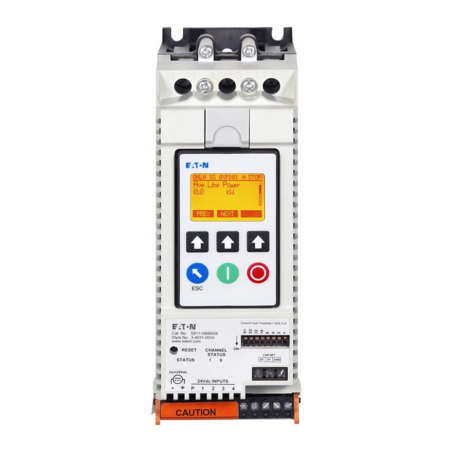
Introduction Introduction Overview The Eaton S811+ Soft Starter from Eaton’s electrical The S811+ Soft Starter utilizes a Digital Interface Module business is an electronic, self-contained, panel- or (DIM) that allows the user to configure the device, read and enclosure-mounted motor soft-starting device. It is intended... -
Page 12: Standards And Certifications
Introduction Standards and Certifications RF Susceptibility Statement It is possible, in the presence of strong RF fields, and at UL 508 ● specific RF frequencies, that this device could indicate an CSA 22.2-14-1995 ● increase of up to 40V in the measured line voltages in the 370 to 420 kHz frequency range;... -
Page 13: Technical Data And Specifications
Technical Data and Specifications Technical Data and Specifications Environmental Environmental Specifications Description Specification Temperature range Operating –40° to 122°F (–40° to 50°C) Storage –58° to 158°F (–50° to 70°C) Elevation Up to 6600 ft (2000m) above 6600 ft (2000m), derate 0.5% per 330 ft (100m) Humidity Functional to 95% noncondensing Operating orientation... -
Page 14: Short-Circuit Ratings-Component
Technical Data and Specifications Short-Circuit Ratings—Component Frame Size Fuses Circuit Breaker Voltage SCCR Rating (A) S811+N… 10 kA S811+R… RK5/J HFD,HKD 10 kA S811+T… RK5/J 18 kA S811+U… RK5/J 30 kA S811+V… HND, RD 42 kA Short-Circuit Ratings—Enclosed Control (Fuses) SCCR Switch Frame Size... -
Page 15: Short-Circuit Information With Iec Breakers
Note: For more details on short-circuit protector selections and enclosure sizing, please refer to the linked spreadsheet on UL ’s website at: http://www.ul.com/global/documents/ offerings/industries/buildingmaterials/industrialcontrolpanels/shortcut.Eaton.xls Note: Suitable for use on a circuit capable of delivering not more than 100,000 rms symmetrical amperes, 600 volts maximum when protected by Class RK5 fuses. -
Page 16: Receipt/Unpacking
The ambient temperature is –58° to 158°F (–50° to 70°C) ● carton damage to the carrier prior to accepting the delivery. Have this information noted on the freight bill. Eaton is not The relative humidity is 0–95%, non-condensing ● responsible for damage incurred in shipping. -
Page 17: Installation
Installation Installation Mounting The S811+ does not require any special tools for mounting operations. To aid with panel layout, refer to the dimension drawings on Pages 8–10. Drill holes per mounting hole location as shown. Mounting hardware may utilize either tapped holes in the panel or lock washers and nuts to secure the soft starter. -
Page 18: Dimensions
Installation Dimensions Approximate Dimensions in inches (mm) S811+N… 1.97 (50.0) 2.66 (67.6) 6.87 5.89 (174.5) 7.37 (149.7) (187.2) 5.35 (135.9) 3.32 (84.4) 0.22 4X Ø (5.5) 6.45 (163.9) S811+R… 3.54 (90.0) 4.38 (111.3) 7.92 6.08 7.44 (201.2) (154.5) (189.0) 5.54 3.49 (140.7) (88.5) -
Page 19: S811+T
Installation Approximate Dimensions in inches (mm) S811+T… 6.47 (164.4) 7.65 (194.4) 5.95 (151.1) 11.77 5.40 12.71 (299.0) (137.3) (322.9) 6X Ø 0.28 (7.1) 5.91 (150.0) 2.95 (75.0) S811+U… 7.16 (181.8) 7.73 (196.3) 6.64 12.72 11.77 (168.6) (323.1) (299.0) 6.09 (154.8) 0.28 6X Ø... -
Page 20: S811+V
Installation Approximate Dimensions in inches (mm) S811+V… 0.236 (6.00) 15.63 (397.0) 16.57 (420.8) 3.05 6.79 (172.5) (77.5) 9.84 (250.0) 11.05 (280.6) 7.39 (187.8) 6.50 (165.1) 0.2650 4X Ø (6.731) S811+ Soft Starter MN03900001E—November 2012... -
Page 21: Power Wiring
Installation Power Wiring See the Motor/Application Considerations in Appendix E for information on typical motor winding configurations. Using the wiring diagrams in below as guides, connect the Line and Motor wiring in accordance with appropriate local and national codes. Inline Connected Soft Starter (default) Power Wiring Diagram S811+…N3S, S811+…P3S, S811+…V3S Note: To provide optimum motor protection the Line and Motor power wiring should be tightly bundled and run... -
Page 22: Selecting Inline Or Inside-The-Delta Operating Configuration
Installation Selecting Inline or Inside-the-Delta Operating Line and Load Power Wiring Configuration S811+N… and S811+R… soft starters utilize box lugs to accomplish line and load power wiring. Refer to the table The mains wiring configuration is set with the Motor Wiring below for wire sizing requirements. -
Page 23: S811+V10
Installation S811+V10… Installation Requirements Install the device in a minimum enclosure size 30 ft Two (2) forced air ventilation fans with a minimum 500 ft /min, at a location for “air in”—bottom right or left corner and “air out”—opposite upper right or left corner. RD circuit breaker. -
Page 24: Lug Installation, S811+N
Installation Lug Installation, S811+N… and S811+R… Control Wiring Inputs Wire the appropriate line and load conductors to the Soft Control wiring is connected to the S811+ by two (2) terminal starter in accordance with federal and local codes. Torque blocks and one (1) RJ12 connection located at the front of fasteners per table on Page 12. -
Page 25: Control Wiring Terminal Blocks
Installation Control Wiring Terminal Blocks CAUTION CAUTION Do not apply 24 Vdc to Network communications Terminal Only apply 24 Vdc to Control Power Terminal Block. All Block. control wiring is 22–12 AWG (0.33–2.5 mm Terminal Block Wiring Capacity CAUTION Number of Do not apply 120 Vac to the control input terminals of the Wire Size Conductors... -
Page 26: Terminal Block Control Input Function Options
Installation Terminal Block Control Input Function Options Programmable control input functions are available on terminals 1, 2, 3, and 4. Please note that all input signals except the analog input must be 18 Vdc or greater (High) and 5 Vdc or less (Low). -
Page 27: Relay Configuration Options
Installation 8–Ext Trip–Control Input 24 Vdc only (maintained) The S811+ 10–Disable OL on Strt–Control Input 24 Vdc only (maintained) unit may be tripped by an external device. Removal of the Applying 24 Vdc to this input prior to the soft starter receiving 24 Vdc signal (maintained) will initiate a Fault Trip action. -
Page 28: Using Auxiliary Contacts
Installation Using Auxiliary Contacts 24 Vdc Signal Control—When a relay is used in conjunction with an electronic control, it is highly recommended that a Often these contacts are used as shown in the illustrations noise suppression/snubber diode be placed across the relay on this page with indicating lamps. -
Page 29: Network Control Terminal Block
Each diagram illustrates a typical wiring scheme for the options described. The additional components shown on the diagrams are not included, but may be purchased from Eaton. Basic Connection Diagram for 3-Wire Pushbutton 24 Vdc Control Voltage Control Terminal Block... -
Page 30: Basic Connection Diagram For 2-Wire Pushbutton
Installation Basic Connection Diagram for 2-Wire Pushbutton 24 Vdc Control Voltage Control Terminal Block (+) Us 24 Vdc (-) Us Aux Relays Ferrite E-Stop Start/Run Maintained Local Momentary Reset Notes A minimum wire of 14 AWG (2.5 mm ) should be used between the control power supply and the control terminal block. -
Page 31: Basic Connection Diagram For Network Control
Installation Basic Connection Diagram for Network Control 24 Vdc Control Voltage Control Terminal Block (+) Us 24 Vdc ( ) Us Aux Relays CH0 Net Ferrite E Stop Maintained Reset Momentary Notes A minimum wire of 14 AWG (2.5 mm ) should be used between the control power supply and the control terminal block. -
Page 32: 24 Vdc Control Power Requirements
Outrush for the power supply ≥ Sum of the Inrush Power ● Input terminals must be 24 Vdc ±10% to provide proper of all the Starters operation of the soft starter. Eaton Recommended 24 Vdc Power Supplies Sealed Inrush Catalog Primary... -
Page 33: Control Wiring Application Notes
24 Vdc Control voltage must not fall below 18 Vdc. If it is desired to place an electromagnetic contactor on the line side of the soft starter, Eaton recommends using level Exchanging a Digital Interface Module (DIM) sense option. With level sense, no additional control circuitry is required. -
Page 34: Power
Functional Description Functional Description Power Note: For soft starters used in an Inside-the-Delta application, use of a shunt trip breaker is highly The S811+ Soft Starter controls the voltage applied to a recommended. The S811+ may be configured to three-phase induction motor in order to control the starting actuate a shunt trip breaker on user selected Fault Trip torque and provide a smooth starting characteristic. -
Page 35: Starting/Stopping Options
Functional Description Starting/Stopping Options The following starting options are available in the S811+ Soft Starter: Voltage Ramp Start This is the most commonly used mode of soft starting. of the Start Ramp time, it quickly completes the voltage Starting at an initial value set by the Initial Torque parameter, ramp and closes the bypass contactor(s). -
Page 36: Current Limit Start
Functional Description Current Limit Start This mode is typically used when it is necessary to limit the Note: Current Limit Starts are not recommended on variable maximum current during start-up due to line power torque load applications like fans and pumps. limitations or other considerations. -
Page 37: Control Functions
Functional Description Control Functions Terminal 1—Start (default)—If 24 Vdc is present at the Permissive terminal, momentary application of 24 Vdc to the Start terminal will initiate a Voltage Ramp or Current Limit Network Control start for the S811+ soft starter. Application of 24 Vdc may be When the S811+ is in Network control and a 24 Vdc signal is maintained present at control block terminal “P”, it is ready to respond... -
Page 38: Level Or Edge Sensing
Functional Description Level or Edge Sensing Edge Sensing Level or Edge Sensing determines how the soft starter Edge sensing (default) selection may be verified by observing reacts to Start control commands after a fault trip has the status of the Run Input Control sub-parameter in the occurred. - Page 39 Functional Description AUTO RESET Reset Mode—Three (3) modes of resetting Fault Trips are available: 0–Manual—Requires pressing Reset button on DIM, pressing Reset button on the face of the S811+, or by providing a signal to an Input Control Terminal configured for this function (Terminal 4 default).
-
Page 40: S811+ Operating Configuration
S811+ Operating Configuration S811+ Operating Configuration Introduction The S811+ has a wide range of operation and protection parameters to enable coordinated motor and load protection. Commonly used parameters are directly accessible through the Digital Interface Module (DIM). The unit is supplied with default settings that accommodate general induction motor applications that provide very basic motor protection. -
Page 41: Transfer Of S811+ Configuration Parameters
S811+ Operating Configuration Predefined keys are used to perform critical functions: Setup and Starting ● Predefined Keys Before You Begin Be Aware of the Following: The Permissive terminal must have 24 Vdc applied to ENABLE start or run commands from any source. To initiate a Stop remove the 24 Vdc Permissive terminal Stop Command input. -
Page 42: Initial Configuration
S811+ Operating Configuration Initial Configuration: It is suggested that the S811+ Soft Starter be configured Set the Operating Parameters to the desired values. before applying the line voltage. Before applying the Line These settings assume the motor has a 1.15 Service voltage, apply 24 Vdc to the Supply connections of the Factor. -
Page 43: S811
S811+ Operating Configuration Operating Parameters—Soft Start Configuration—S811+ …P3S Premium Minimum Maximum Default Inline Inline Inline Access Soft Start Config Menu Units (InsideDelta) (InsideDelta) (InsideDelta) Notes Level Mtr Nameplate FLA S811+N37… Amps 11 (19) 37 (65) 11 (19) Motor FLA parameter must be set to motor nameplate FLA to achieve proper overload S811+N66…... -
Page 44: Operating Parameters-Soft Start Configuration-S811
S811+ Operating Configuration Operating Parameters—Soft Start Configuration—S811+ …V3S Premium (690 Volt) Minimum Maximum Default Access Soft Start Config Menu Units Inline Inline Inline Notes Level Mtr Nameplate FLA S811+T18… Amps Motor FLA parameter must be set to motor nameplate FLA to achieve proper overload S811+T24…... -
Page 45: Protection Parameters
S811+ Operating Configuration Protection Parameters Fault Codes For additional details on troubleshooting fault codes and In addition to motor overload protection, the S811+ has fault conditions, please refer to Troubleshooting and many programmable features designed to protect the motor. Appendix I. Incoming Line Phase Reversal, Loss, Imbalance, Over ●... -
Page 46: Fault Trip/Fault Warning/Disable Options
S811+ Operating Configuration Fault Trip/Fault Warning/Disable Options The S811+ has a comprehensive array of protection parameters. Selected Protection Parameters have options to be set to a Fault Trip, Fault Warning, or disabled. Disabling fault protections is not recommended. Fault Code Options Code Description Fault Options... -
Page 47: Alarm-No-Trip Option
S811+ Operating Configuration Alarm-No-Trip Option When the Alarm-No-Trip option is enabled, only faults critical to motor control are effective. These faults are noted in table The Alarm-No-Trip option is intended for use with (1) below: applications that have motor run-to-destruction protocols in the application specifications. -
Page 48: Mains Voltage Operating Faults-Full Scr Start
S811+ Operating Configuration When the Alarm-No-Trip option is enabled, mains voltage When the Alarm-No-Trip option is enabled, faults noted in operating conditions noted in table (2) below are monitored table (3) below are monitored by the S811+. One or more by the S811+. -
Page 49: Thermal Overload
S811+ Operating Configuration Thermal Overload Soft Start Configuration Application Notes The S811+ Soft Starter features an electronic motor overload a) Voltage Ramp Start Configuration protection feature. It is designed to protect the motor and Default values may be used for Start Time and Initial power wiring against overheating caused by operating at Torque. -
Page 50: Initial Torque Settings
S811+ Operating Configuration The table below notes the values of Initial Torque settings as Code Letters a percentage of Locked Rotor Current. Kilovolt-Ampere per hp with Locked Rotor Code Letter Minimum Maximum Initial Torque Settings 3.14 Torque Current as % Setting Locked Rotor Initial Motor Torque... -
Page 51: Troubleshooting
If you have worked through the following troubleshooting procedure and find that you require further WARNING assistance, please contact Eaton. Please have the following information ready when you call: HIGH VOLTAGE. Do not work on energized equipment unless absolutely required. If the troubleshooting... -
Page 52: Define The Problem
Troubleshooting Define the Problem If the S811+ Soft Starter fails to respond in any way to a start command., look at the Digital Interface Module of the S811+ Soft Starter and determine the fault status of the unit. The following troubleshooting flowcharts provide a logical sequence to determine issues and suggest probable solutions to each problem. -
Page 53: Troubleshooting-S811+ Stopped Or Faulted
Troubleshooting Note: If connected to a network, starting the S811+ from Refer to the flowchart on Page 44 to aid in determining the appropriate corrective action during the various run phases of the Control Input terminal block may isolate problems operation. -
Page 54: Local Control Troubleshooting Flow Chart
Correct fault condition Contact Contact Eaton Eaton Support Support In extreme cases, it may be necessary to reset parameter settings and operating values to restore proper operation. The S811+ may be reset by following the instruction below. -
Page 55: Lug Kits
Accessories Accessories Lug Kits Communications Contact EatonCare for availability of communications Lug Kits—S811+T, U… adapters. Description Part Number Communications 2 cable connections, 4 AWG to 1/0 cable EML22 Catalog 1 cable connection, 4/0 to 500 kcmil cable EML23 Description Number 2 cable connections. -
Page 56: Appendix A-Parameters
Appendix A—Parameters Appendix A—Parameters Monitoring Menu Monitoring Menu Access Description Units Level Flt/Warn Active Fault/Warn List Fault/Warn History 3Ø Line Currents Amps Current as % FLA DC Cntrl Voltage Volts 3Ø Pole Voltages Volts Line Frequency Phase Sequence Ave Line Power Power Factor Thermal Memory Pole Temp... -
Page 57: Soft Start Config Menu
Appendix A—Parameters Soft Start Config Menu Soft Start Config—S811+ …N3S Standard Minimum Maximum Default Inline Inline Inline Access Soft Start Config Menu Units (InsideDelta) (InsideDelta) (InsideDelta) Notes Level Mtr Nameplate FLA S811+N37… Amps 11 (19) 37 (65) 11 (19) Motor FLA parameter must be set to motor nameplate FLA to achieve proper overload S811+N66…... -
Page 58: Soft Start Config-S811
Appendix A—Parameters Soft Start Config—S811+ …P3S Premium Minimum Maximum Default Inline Inline Inline Access Soft Start Config Menu Units (InsideDelta) (InsideDelta) (InsideDelta) Notes Level Mtr Nameplate FLA S811+N37… Amps 11 (19) 37 (65) 11 (19) Motor FLA parameter must be set to motor nameplate FLA to achieve proper overload S811+N66…... -
Page 59: Soft Start Config-S811
Appendix A—Parameters Soft Start Config—S811+ …V3S Premium (690 Volt) Minimum Maximum Default Access Soft Start Config Menu Units Inline Inline Inline Notes Level Mtr Nameplate FLA S811+T18… Amps Motor FLA parameter must be set to motor nameplate FLA to achieve proper overload S811+T24…... -
Page 60: Protection Menu
Appendix A—Parameters Protection Menu Protections Menu—All Catalog Numbers Fault Code Protections Menu Units Minimum Maximum Default Notes Overload Fault Enable 0 = Disable 1 = Enable 2 = Warning Ovld On Start 0 = Disable 1 = Enable Motor Rated Volt volts volts 690 volt option... -
Page 61: Advanced I/O Menu
Appendix A—Parameters Protections Menu, continued Fault Code Protections Menu Units Minimum Maximum Default Notes 3Ø Power Fault—Enable 0 = Disable 1 = Enable 2 = Warning Low Power Trip Level High Power Trip Level Pwr Flt Trip Dly seconds 74, 75 Rated Line Freq Line Freq Fault—Enable 0 = Disable... -
Page 62: Parameter List-Advanced I/O Setup
Appendix A—Parameters Parameter List—Advanced I/O Setup—All Catalog Numbers, continued Advanced I/O Access Setup Menu Units Minimum Maximum Default Notes Level Relay Config Entry 0 = Terminals 13, 14 0 = No Function 1 = Fault Entry 1 = Terminals 95, 96, 98 0 2 = Fault NOT Entry 2 = Network Output 1 3 = Bypassed... -
Page 63: Network Setup Menu
Appendix A—Parameters Network Setup Menu Network Setup Access Network Setup Minimum Maximum Default Notes Level Comm Loss Action 0 = Auto Stop 1 = Auto Run1 2 = Unavailable 3 = Hold Last 4 = Unavailable 5 = Unavailable 6 = Unavailable 7 = All Stop Fault Modbus Baud Rate 0 = 1200... -
Page 64: Lcd Dim Setup Menu
Appendix A—Parameters LCD DIM Setup Menu LCD DIM Setup Access LCD DIM Setup Units Minimum Maximum Default Level Upload Settings Dnload Settings DIM Access Level Access Timeout seconds Change Password Clear Fault Hist Get Register Set Register Run Button Delay seconds Removable DIM Fault Disp Tmout... -
Page 65: Appendix B-Protection
Appendix B—Protection Appendix B—Protection Thermal Overload Overload—Adjustment Range—Inside-the-Delta Connected The S811+ Soft Starter features an electronic motor overload Catalog protection feature. This is intended to protect the motor and Number Default Notes power wiring against overheating caused by excessive current for extended periods of time. S811+N37…... -
Page 66: Thermal Motor Overload Times
Appendix B—Protection Once the trip level reaches level 3, it will take 144 minutes to go back to level 2, then 96 minutes to get back to level 1. To get from level 3 to a reset thermal overload at level 1, it takes 240 minutes without a trip. -
Page 67: Overload Trip Curves
Appendix B—Protection Overload Trip Curves 10000.0 115% Class 5 1000.0 Class 10 Class 20 Class 30 100.0 Class 30 Class 20 Class 10 Class 5 10.0 Percent FLA S811+ Soft Starter MN03900001E—November 2012... -
Page 68: Appendix C-Ratings, Cooling And Power Losses-Inline
Appendix C—Ratings, Cooling and Power Losses—Inline Appendix C—Ratings, Cooling and Power Losses—Inline Power Ratings Standard Duty—15 Second Ramp, 300% Current Limit at 40°C—Inline Connection Three-Phase Motors kW Rating (50 Hz) hp Rating (60 Hz) 230V 380–400V 440V 200V 230V 460V 575–690V Maximum Catalog... -
Page 69: Severe Duty-30 Second Ramp And/Or 450% Current
Appendix C—Ratings, Cooling and Power Losses—Inline Severe Duty—30 Second Ramp and/or 450% Current Limit at 50°C—Inline Connection Three-Phase Motors kW Rating (50 Hz) hp Rating (60 Hz) 230V 380–400V 440V 200V 230V 460V 575–690V Maximum Catalog Current 1.0SF 1.0SF 1.0SF 1.0SF 1.15SF 1.0SF... -
Page 70: Appendix D-Ratings, Cooling And Power Losses-Inside-The-Delta
Appendix D—Ratings, Cooling and Power Losses—Inside-the-Delta Appendix D—Ratings, Cooling and Power Losses—Inside-the-Delta Power Ratings Standard Duty—15 Second Ramp, 300% Current Limit at 40°C—Inside-the-Delta Connection Three-Phase Motors kW Rating (50 Hz) hp Rating (60 Hz) Maximum 230V 380–400V 440V 200V 230V 460V 575–690V Continuous... -
Page 71: Severe Duty-30 Second Ramp And/Or 450% Current Limit At 50°C-Inside-The-Delta Connection
Appendix D—Ratings, Cooling and Power Losses—Inside-the-Delta Severe Duty—30 Second Ramp and/or 450% Current Limit at 50°C—Inside-the-Delta Connection Three-Phase Motors kW Rating (50 Hz) hp Rating (60 Hz) Maximum 230V 380–400V 440V 200V 230V 460V 575–690V Continuous Catalog Line Current 1.0SF 1.0SF 1.0SF 1.0SF... -
Page 72: Maximum Power Loss
Appendix D—Ratings, Cooling and Power Losses—Inside-the-Delta Power Losses The following table lists the maximum power loss for each S811+ Soft Starter when it is operating in bypass at the maximum frame size current. These losses should be used in conjunction with the losses of another cabinet mounted device to determine the enclosure size and any cooling requirements. -
Page 73: Appendix E-Motor/Application Considerations
Appendix E—Motor/Application Considerations Appendix E—Motor/Application Considerations Squirrel Cage Motor Dual Voltage Motor This is the most common application. A dual voltage motor should be wired into the appropriate configuration for the line voltage it is being applied to. Refer The motor is configured with three motor leads available. to the motor nameplate for the correct wiring information. -
Page 74: Appendix F-Pump Control Option
Appendix F—Pump Control Option Appendix F—Pump Control Option Pump Control Option Adjustment All of the adjustments to the S811+ Premium Soft Starter are This option is intended to reduce the potential for water made as noted in this user manual. The major difference hammer in a centrifugal pump system by utilizing a starting between the standard S811+ Soft Starter and Premium is and stopping algorithm developed for pump control. -
Page 75: Appendix G-Modbus Register Map
Appendix G—Modbus Register Map Appendix G—Modbus Register Map Register Map Modbus Data Register Data Parameter Length Number Read/Write Type Description Motor Control Status UINT8 status Running1 Running2 Permissive Ramp2 LocalControlStatus Faulted Warning In bypass Active Faults & Warning List UINT16 Latest Fault/Warning code (latest Fault) UINT16... -
Page 76: Appendix G-Modbus Register Map
Appendix G—Modbus Register Map Register Map, continued Modbus Data Register Data Parameter Length Number Read/Write Type Description Three-Phase RMS AC Voltage UINT16 L1 RMS Voltage UINT16 L2 RMS Voltage UINT16 L3 RMS Voltage Total Number of Motor Starts UINT32 # of motor starts Reg311 = LSB1, LSB0 Reg312 = MSB, LSB2 Analog Input Percent of Rated... - Page 77 Appendix G—Modbus Register Map Register Map, continued Modbus Data Register Data Parameter Length Number Read/Write Type Description Fault Queue UINT16 Latest Fault/Warning code (Fault/Warning codes are UINT16 2nd Latest Fault/Warning code not repeated in the list) UINT16 3rd Latest Fault/Warning code UINT16 4th Latest Fault/Warning code UINT16...
- Page 78 Appendix G—Modbus Register Map Register Map, continued Modbus Data Register Data Parameter Length Number Read/Write Type Description Scaled Average Three Phase UINT16 Scaled Average pole current in Amps Currents in amps—Pole Scaled Three Phase Currents in UINT16 L1 RMS pole current in Amps amps—Pole UINT16 L2 RMS pole current in Amps...
- Page 79 Appendix G—Modbus Register Map Register Map, continued Modbus Data Register Data Parameter Length Number Read/Write Type Description Modbus Motor Two Wire Control 1 UINT8 Description Run1—Level Sense Run2—Level Sense reserved Fault Reset reserved reserved reserved Ramp2 enable Network Inputs UINT8 Description C441/Network Input#1 C441/Network Input#2...
- Page 80 Appendix G—Modbus Register Map Register Map, continued Modbus Data Register Data Parameter Length Number Read/Write Type Description Motor Start Method UINT8 0 = Voltage Ramp 1 = Current Limit 2 = Unavailable 3 = Pump Start (w pump option) Percent Initial Torque UINT8 0–100% Motor Start Ramp Time...
- Page 81 Appendix G—Modbus Register Map Register Map, continued Modbus Data Register Data Parameter Length Number Read/Write Type Description Motor Control Output 0 = No function 1 = Faulted Configuration 2 = Not Faulted S811 output#1 cfg UINT16 3 = Bypass S811 output#2 cfg UINT16 4 = Not Bypass Network output#1 cfg...
- Page 82 Appendix G—Modbus Register Map Register Map, continued Modbus Data Register Data Parameter Length Number Read/Write Type Description Motor Voltage Imbalance Fault UINT8 1–100% Level Motor Voltage Imbalance Fault UINT16 0.1–60.0 sec (in 0.1 sec) Duration Motor Under Voltage Fault Enable 1 UINT8 0 = Protection disabled 1 = Fault enabled...
- Page 83 Appendix G—Modbus Register Map Register Map, continued Modbus Data Register Data Parameter Length Number Read/Write Type Description SCR Shorted Fault Enable UINT8 0 = Protection disabled 1 = Fault enabled 2 = Warning enabled Alarm-No-Trip Enable UINT8 1 = enable 0 = disable Motor Control Start Delay UINT8...
- Page 84 Appendix G—Modbus Register Map Register Map, continued Modbus Data Register Data Parameter Length Number Read/Write Type Description Modbus_Production List 1000 UINT16 1st Modbus Production Register# UINT16 2nd Modbus Production Register# Note that the values must be 1001 Modbus Register Address (i.e., 1002 UINT16 3rdt Modbus Production Register#...
-
Page 85: Appendix H-Universal Communications Adapter
Appendix H—Universal Communications Adapter Appendix H—Universal Communications Adapter External adapters can be connected to the S811+ to enable the unit to be controlled by networks other than Modbus. Connect the adapter in accordance with the wiring diagram below. Wiring Diagram S811+ CH0 Het D1 GND RS485... -
Page 86: Appendix I-Troubleshooting Guide
Appendix I—Troubleshooting Guide Appendix I—Troubleshooting Guide This guide is intended to provide the information necessary The following Fault Codes may be experienced during to successfully troubleshoot issues that may occur during commissioning of a new installation or a new soft start into the operation of the S611 Soft Starter. -
Page 87: General Information
Appendix I—Troubleshooting Guide General Information LEVEL Sense ● Most commonly used Start Control parameter setting. 24 Vdc Control Power—Terminal Block Connections ● Maintained Terminal “1” energized: ● Run Enable 24 Vdc applied to Terminal “P” , This 24 Vdc ● input must be maintained continuously during RUN –... - Page 88 Appendix I—Troubleshooting Guide Thermal Memory START Command Troubleshooting ● ● This parameter is not the same as Thermal Overload. From the Terminal Block ● ● Parameter may be viewed in the Monitoring Menu. – Verify that Terminal “P” is energized continuously. ●...
-
Page 89: S811+ Fault Codes
Appendix I—Troubleshooting Guide S811+ Fault Codes Code Fault Status Condition Solution Fault Warning Impending OL Trip Overload trip is impending. Motor current 120% above FLA parameter setting. Firmware Fault Trip/Fault Component failure on printed Failed unit. Contact EatonCare for service information. Incompatibility or Warning/Diable circuit board. - Page 90 Appendix I—Troubleshooting Guide S811+ Fault Codes, continued Code Fault Status Condition Solution Phase Imbalance Fault Trip Phase imbalance exceeds Correct imbalance problem with mains. parameter value. Fault Warning Increase the Current and/or Voltage Fault Imbalance parameters. Disable Disable the fault if the other issues cannot be resolved. Notes: Phase imbalance may be impacted by voltage issues and/or current issues.
- Page 91 (not Disable recommended). Not field repairable, contact Eaton support. Notes: There are three (3) independent temperature sensors that incorporate a current sensor on each power pole (phase). This fault may be generated by any one of the sensors.
- Page 92 Appendix I—Troubleshooting Guide S811+ Fault Codes, continued Code Fault Status Condition Solution Motor High Power Fault Trip Average power has increased Inspect application for cause of high power. above the high threshold set by Fault Warning Increase High Power Trip threshold user.
- Page 93 Appendix I—Troubleshooting Guide S811+ Fault Codes, continued Code Fault Status Condition Solution Internal Comm2 Fault Fault Trip Internal communications error. Try a 24 Vdc control voltage power cycle to attempt to clear problem. Excessive electrical noise or Contact EatonCare for service. hardware failure.
- Page 94 Appendix I—Troubleshooting Guide S811+ Fault Codes, continued Code Fault Status Condition Solution V Zero Cross Lost Fault Trip Mains voltage lost. Restore mains or lost phases. Phase L1 or L3 lost. Verify that the load is connected and any disconnect devices are properly engaged.
- Page 95 Appendix I—Troubleshooting Guide S811+ Fault Codes, continued Code Fault Status Condition Solution Line Frequency (low) Fault Trip Mains input voltage frequency Increase line frequency to within limits. has decreased below the Fault Warning Adjust parameter limits. threshold set by the user. Disable Notes: To address line frequency instability and/or excessive variations, adjust limit parameters according.
Need help?
Do you have a question about the S811+N37 series and is the answer not in the manual?
Questions and answers