
Related Manuals for Eaton SC300


Summary of Contents for Eaton SC300
- Page 1 SC300 System Controller Operation Handbook Issue: IPN 997-00012-03 B2 Issue Date: July 2018 Eaton Corporation Telecommunications Power Solutions dcpower.eaton.com DCinfo@eaton.com...
- Page 2 The information contained in this literature is subject to change without notice. Subject to the right to use its equipment, Eaton Corporation does not convey any right, title or interest in its intellectual property, including, without limitation, its patents, copyrights and know-how.
-
Page 3: Audience
About T his Gui de Scope This guide covers operation of the SC300 system controller. See SC300 Identity Information on page 17 to determine the version of the embedded software. Audience This guide is intended for use by: Installers competent in: •... -
Page 4: Table Of Contents
SC300 Operation ..........................7 Overview ........................... 7 Starting the SC300 ........................8 Main Screen Shortcut Keys ......................9 SC300 Operation using the Keypad and Screen ..............9 Soft Keys ............................10 Navigation Keys ..........................10 Main Menu Navigation ......................... 11 Sub-menu Tabs .......................... - Page 5 Web Access Security ........................117 RADIUS Authentication ......................119 Maintenance Overview ..........................121 Troubleshooting ........................122 Replacing the System Controller or I/O Board ..............127 Copyright © 2007-2018 Eaton Corporation. All Rights Reserved. IPN 997-00012-03 B2 Issue B2 July 2018...
- Page 6 SC300 Mappings .......................... 145 I/O Board Mapping ......................145 Digital Output (Relay) Activation ..................149 Equipment Incident Report ....................... 150 Worldwide Support ........................153 Index Copyright © 2007-2018 Eaton Corporation. All Rights Reserved. IPN 997-00012-03 B2 Issue B2 July 2018...
-
Page 7: General Description
Chapter 1 General Description Gener al D escription Overview Topic Page SC300 System Controller Input / Output Board Connections Compatible Software Copyright © 2007-2018 Eaton Corporation. All Rights Reserved. IPN 997-00012-03 B2 Issue B2 July 2018... -
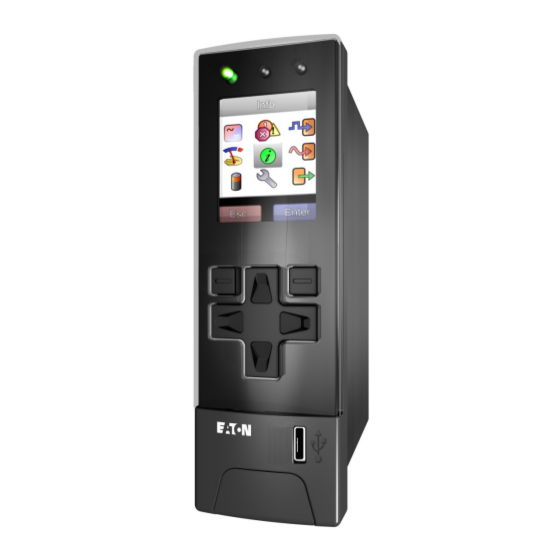
Page 8: Sc300 System Controller
Some configuration file changes can be made with the keypad, or all settings can be changed via a PC connected to the SC300 through a network or the USB interface (see details on page 23). -
Page 9: Input/Output Board
General Description Input/Output Board The Input / Output (I/O) board provides the I/O interfaces and connections for the SC300 system controller. The I/O board includes a range of sense inputs for dc power system control and monitoring. It also allows real time data collection from building services and other external devices, and relay outputs for alarm signals or control of external devices. - Page 10 Power/Comms OK LED (green) 15. LVD contactor 1 connector (XH4) and status LED (green) See Troubleshooting on page 122 for details of I/O board LED signals. Copyright © 2007-2018 Eaton Corporation. All Rights Reserved. IPN 997-00012-03 B2 Issue B2 July 2018...
-
Page 11: Connections
General Description Connections The following diagram shows the connections between the SC300, the I/O board, the other dc power system components and external devices, for the IOBGP-00. Other I/O board options have additional digital inputs, outputs, and an extra LVD. -
Page 12: Compatible Software
SC300 Handbook Compatible Software The following software is compatible with the SC300 system controller: PowerManagerII Remote Control and Monitoring Software. Contact your Eaton dc product • supplier for further information (see Worldwide Support on page 153). Recommended web browsers: Microsoft Internet Explorer 11 or later, Mozilla Firefox 3.0 or... -
Page 13: Sc300 Operation
SC300 Operation SC300 Operati on Overview Topic Page Starting the SC300 SC300 Operation using the Keypad and Screen SC300 Operation Using a PC/Laptop SC300 Identity Information SC300 Internal Clock Language Options SC300 Firmware Upgrade Configuration File Backup and Restore Copyright ©... -
Page 14: Starting The Sc300
SC300 Handbook Starting the SC300 When dc power is applied to the SC300 (via the RXP connector YS11) the start-up sequence begins: Start-up screen Main screen Menu screen Approx. 120s Summary screen The values shown on the Main See navigation details on page 11. -
Page 15: Main Screen Shortcut Keys
From the Main Screen go directly to the Settings screen. From the Main Screen go directly to the Control Processes screen. From the Main Screen go directly to the Analogs screen. SC300 Operation using the Keypad and Screen Soft key 1 label Soft key 1... -
Page 16: Soft Keys
Move left/right between segments of a multiple segment value in a • configuration screen. From the Main Screen, press left arrow to go to Control Processes, and • right arrow to go to Analogs. Copyright © 2007-2018 Eaton Corporation. All Rights Reserved. IPN 997-00012-03 B2 Issue B2 July 2018... -
Page 17: Main Menu Navigation
At each menu screen press Enter to access the associated configuration menu screen(s). These menus have multiple configuration menu screens. See details on page 12. Copyright © 2007-2018 Eaton Corporation. All Rights Reserved. IPN 997-00012-03 B2 Issue B2 July 2018... -
Page 18: Sub-Menu Tabs
List of active alarms. Alarm settings. Battery Sub-menus Mid-point monitoring Battery settings. LVD settings. settings. Settings Sub-menus Registered Input / SC300 settings. Output boards. Copyright © 2007-2018 Eaton Corporation. All Rights Reserved. IPN 997-00012-03 B2 Issue B2 July 2018... -
Page 19: Changing A Configuration Setting Using The Keypad
► To use the SC300 when access is set to PIN Protected At the Main Screen press Menu. The Logon screen appears. • If the Access PIN is not known then press Skip to use the SC300 with Read Only access. • If the Access PIN is known: •... -
Page 20: Display Settings
The functions of the navigations keys also change to suit the new display orientation. Main Screen Parameters The parameters displayed on the SC300 main screen are configurable. Either two large or three small parameters can be displayed. The default settings are two large parameters with the values Bus Voltage and Rectifier Current. -
Page 21: Display Time-Out
• In DCTools, go to Configuration > Communications > Front Panel. • When Disabled, the audible indicator will still indicate an invalid key press. Copyright © 2007-2018 Eaton Corporation. All Rights Reserved. IPN 997-00012-03 B2 Issue B2 July 2018... -
Page 22: Sc300 Operation Using A Pc/Laptop
DCTools can be run on a PC/laptop connected to the SC300's USB port. DCTools can also be run on a remote PC/laptop connected to the SC300's RS232 serial port (via a modem) or Ethernet port. For remote PC/laptop connection details see Communications Options on page 104. -
Page 23: Sc300 Identity Information
Identity > Software (App Version) software in the SC300 (factory set). DCTools: Configuration > Identity > Software If required, the following site specific information can be stored in the SC300 to assist site management. Parameter Description Where to find: System... - Page 24 Modified been changed from the last loaded configuration file. If the current configuration is corrupted for any reason, the SC300 will revert to this configuration. Copyright © 2007-2018 Eaton Corporation. All Rights Reserved. IPN 997-00012-03 B2 Issue B2 July 2018...
-
Page 25: Generic System Types
SC300 Operation Generic System Types If the user does not have a suitable configuration file for a new SC300, or he/she needs to change the operating voltage of a system, then the Generic System Types may be used as a starting point. -
Page 26: Sc300 Internal Clock
Press Enter on the keyboard. Then select Apply in the Changes window. Time Synchronization If required, the SC300 time can be synchronized either to the internal time of a PC or laptop, or to a reference time server using SNTP protocol (SC300 must have access to the server). - Page 27 The SC300 uses an internal lithium battery to keep the clock running while the SC300 is not powered up. Predicted life is at least three years. Life depends on the time the SC300 is not powered up, temperature, and battery age.
-
Page 28: Language Options
Click on Next then follow the prompts to add the language. Language selection An SC300 can hold multiple language files and any of these can be selected for the LCD and Web pages. English is always available; other languages can be loaded as needed. -
Page 29: Sc300 Firmware Upgrade
9), or all settings can be edited using a PC/laptop with DCTools (see details on page 16) or remotely, see Communications Options on page 104. The configuration file settings in the SC300 can be saved to (Backup) or loaded from (Restore) a PC/laptop using Web or DCTools. See Backup and Restore on page 23. - Page 30 ► To load configuration files from SC200 or older SC300 versions This is useful when it is required to update an SC200 configuration file to use in an SC300. Passwords are not copied from the SC200. These will need to be re-entered.
-
Page 31: System Operation
System Operation Overview Topic Page Voltage Control Rectifiers Low Voltage Disconnect (LVD) Alarms Batteries Generator Control Alternative Energy Input Metering Input / Output (I/O) Data Logging Copyright © 2007-2018 Eaton Corporation. All Rights Reserved. IPN 997-00012-03 B2 Issue B2 July 2018... -
Page 32: Voltage Control
If ac fails then any active control process stops. No control process can start until the ac supply is restored. Copyright © 2007-2018 Eaton Corporation. All Rights Reserved. IPN 997-00012-03 B2 Issue B2 July 2018... -
Page 33: Float Voltage
The system voltage is limited by maximum and minimum values. The values are viewable in DCTools/Web at Control Processes > Voltage Control. These values are not configurable by Web or DCTools. If these must be changed, contact your Eaton representative for access to ICE software. -
Page 34: Active Voltage Control (Avc)
Engine Run Limit applies when the SC300 determines that an ac standby generator is running. If an Engine Run Digital Input is available (see below), then the SC300 uses this to determine if the generator is running. If an Engine Run Digital Input is not available then the SC300 uses other values to determine if the generator is running. - Page 35 C10 DCTools/Web: Control Battery Capacity. Processes > Battery Current Limit Engine Run Limit The Battery Current Limit setting when Engine Run State is active. Copyright © 2007-2018 Eaton Corporation. All Rights Reserved. IPN 997-00012-03 B2 Issue B2 July 2018...
-
Page 36: Battery Test
The SC300 temporarily reduces the output voltage of the rectifiers to just below the bus voltage for a set duration. The battery then supplies power to the load. A battery test passes if the battery voltage remains above a predetermined level for the duration of the test. -
Page 37: Equalize
Pending and it will start as soon as conditions allow. Use Stop Equalize to cancel a Pending Equalize. ► To enable Equalize (or to start or stop Equalize manually) Use the SC300 keypad to go to: Control Processes > Equalize. • Or, in DCTools/Web go to: Control Processes > Equalize. -
Page 38: Fast Charge
Pending. Next Start Time The start time of the next scheduled Equalize. Time shown on SC300 is UTC. Time on SC300: Control Processes > PC running Web is local time. See Equalize SC300 Internal Clock on page 19. - Page 39 System Operation ► To enable Fast Charge (or to stop Fast Charge manually) Use the SC300 keypad to go to: Control Processes > Fast Charge. • Or, in Web go to: Control Processes > Fast Charge. • Information The following information is available about Fast Charge.
- Page 40 Set the following parameters. Parameter Description Where to find: Fast Charge The SC300 will charge the batteries at up to this Voltage voltage until the end of fast charge. Boost If this is enabled, the SC300 will set rectifiers elevated charge voltage until the Fast Charge Voltage is reached.
-
Page 41: Temperature Compensation
Temperature Compensation does NOT function during a Battery Test. ► To enable Temperature Compensation Use the SC300 keypad to go to: Control Processes > Temp. Compensation > Enable. • Or, in DCTools/Web go to: Control Processes > Temperature Compensation. -
Page 42: Peak Load Reduction (Plr)
Eaton EDREM. While PLR is active, the SC300 turns down the rectifier voltage to just below the DC bus voltage. The batteries will discharge into the load, while the rectifiers provide a backup if the battery fails. - Page 43 System Operation PLR may be triggered manually from the SC300 web interface, automatically from a Smart Alarm, or remotely from EDREM or a similar application. ► To enable PLR Use the SC300 keypad to go to: Control Processes > Peak Load Reduction.
-
Page 44: Solar Charger Power Share
Where a DC power system has energy inputs both from AC mains supply (or AC generator) and solar or wind, then the SC300 must share the load power between these sources. Generally, the preference is for the load to be supplied from the alternative energy source first, and take energy from AC only when there is not enough solar or wind energy. - Page 45 AC rectifiers. The SC300 AVC function controls the overall charge voltage so that the bus is set to the correct voltage setting, even with solar charger offset included.
-
Page 46: Rectifiers
SC300 Handbook Rectifiers The SC300 registers all rectifier modules and solar chargers as they are inserted into the dc power system. Information The following information is available about rectifiers. Parameter Description Where to find: Registered Number of rectifiers controlled by the SC300... - Page 47 Rectifier manufacturer's model number. SC300: Rectifiers > Enter (Use Left and Right keys to Software Version Version of rectifier embedded software. scroll to other rectifiers) Not available DCTools/Web Copyright © 2007-2018 Eaton Corporation. All Rights Reserved. IPN 997-00012-03 B2 Issue B2 July 2018...
- Page 48 Where to find: Phase-1 The serial number of the rectifier assigned as “Phase 1”. When this is set correctly, it enables the SC300 to assign a phase number to all rectifiers. Only applies to rectifiers that support phase detection, including APR48-ES and NPR48-ES.
-
Page 49: Phase Detection
(see Load Based Rectifier Shutdown on page 44). ► To disable Rectifier Shutdown Use the SC300 keypad to go to: Rectifiers > Settings (tab) > set Rectifier Shutdown to Disabled. • Or, in DCTools/Web go to: Rectifiers > Configuration> set Shutdown to Disabled. - Page 50 The rectifier(s) will then resume normal operation. The SC300 will restart any shutdown rectifiers if: ac has failed, or more than one rectifier has failed, or the bus voltage is below the Low Load threshold, or Rectifier Shutdown is set to Disabled, or Rectifier Shutdown is set to Automatic.
-
Page 51: Load Based Rectifier Shutdown
► To enable Load Based Rectifier Shutdown Use the SC300 keypad to go to: Rectifiers > Settings (tab) > set Rectifier Shutdown to Automatic. • Or, in DCTools/Web go to: Rectifiers > set Shutdown to Automatic. - Page 52 Shutdown does not occur if shutting down a rectifier would push load percentage above High Threshold. Interval The time interval that the SC300 will cycle rectifiers when the LBRS process is active. Reset Run Times Sets the run time of all rectifiers to zero.
-
Page 53: Low Voltage Disconnect (Lvd)
The SC300 has 16 independent LVD control channels (LVD 1 to LVD 16). Each channel can control one or more of up to 16 contactors, with coil voltages from 12V to 48V nominal. -
Page 54: Typical Lvd Arrangements
More complex arrangements with up to 16 contactors and a selection of disconnection criteria are possible with the SC300 system controller. The exact arrangement(s) used in a particular Eaton dc power system will be described in the Installation and Operation Guide. -
Page 55: Lvd Operation
If the check box is cleared LVD functions can only be accessed using DCTools/Web. ► To manually connect or disconnect an LVD control channel from the front panel Use the SC300 keypad to go to: Battery > LVDs > LVD 1 - LVD 16 > Details > Manual Control. •... -
Page 56: Lvd Setup
► To Enable (Add) an LVD using the SC300 keypad Control and configuration of LVDs and contactors is only available from the SC300 keypad if Allow Front Panel LVD Control is TRUE. See LVD Operation on page 49. Go to: Battery > LVDs. - Page 57 If an LVD is manually disconnected, it will Web: Control Processes > Manual Reconnect reconnect again after this time. Timeout Period Not available on DCTools Copyright © 2007-2018 Eaton Corporation. All Rights Reserved. IPN 997-00012-03 B2 Issue B2 July 2018...
- Page 58 * If the LVD channel operates contactors used as a load-disconnect, ensure the Reconnect Voltage is set higher than the expected open-circuit recovery voltage of the discharged batteries. Copyright © 2007-2018 Eaton Corporation. All Rights Reserved. IPN 997-00012-03 B2 Issue B2 July 2018...
-
Page 59: Smart Alarm Disconnect
An unwanted LVD disconnect may occur if Smart Alarm Disconnect uses a sensor which becomes faulty or disconnected. An unwanted LVD disconnect may occur if Battery Time Remaining is used as a source for Smart Alarm Disconnect. Copyright © 2007-2018 Eaton Corporation. All Rights Reserved. IPN 997-00012-03 B2 Issue B2 July 2018... -
Page 60: Alarms
Alarms An SC300 supplied with a standard configuration file (see details on page 23) has a standard set of alarms configured and enabled. This will be sufficient for standard dc power system operation. For specific alarm arrangements all SC300 alarms can be individually enabled or disabled and are configurable. -
Page 61: Active Alarm Indications
Critical Major SC300 Minor alarm LED will turn on. See details on page Minor Warning If the SC300 audible indicator is enabled, it See details on page Critical will sound until a key is pressed. Major Minor The alarm name and severity icon will be See details on page 8. -
Page 62: Alarm Change Indication
SC300 Handbook ► To view a list of active alarms Use the SC300 keypad to go to: Alarms. • Or, in DCTools/Web, go to System. • Alarm Change Indication The time and date of the last alarm state change is shown in the web view in Alarm States, Change column. -
Page 63: System Alarm Configuration
107). Notes Type any required description. When the alarm is active the text will be displayed on the SC300 and included in the SNMP trap (if used). The notes can provide instructions about what action to take when the alarm occurs. -
Page 64: System Overload Alarms
The output power of the system as a percentage SC300: Analogs of the total nominal power the system is capable DCTools/ Web: Analog of supplying. Inputs Copyright © 2007-2018 Eaton Corporation. All Rights Reserved. IPN 997-00012-03 B2 Issue B2 July 2018... - Page 65 System Overload Recognition Period. Measured as a percentage of total rectifier capacity. System Overload See System Overload Threshold above. Threshold B Copyright © 2007-2018 Eaton Corporation. All Rights Reserved. IPN 997-00012-03 B2 Issue B2 July 2018...
-
Page 66: Smart Alarms
Smart Alarms may also be used to start and stop control functions, including Equalize, Peak Load Reduction, and LVD. For more information and application examples contact your Eaton DC product supplier and request Eaton Application Note AN0106, SC200 Advanced Alarm Features. This also applies to SC300. - Page 67 Alarm becomes inactive. E.g. If this is set to 2, by 2 counter. then two active to inactive transitions are required before the Smart Alarm becomes inactive. Copyright © 2007-2018 Eaton Corporation. All Rights Reserved. IPN 997-00012-03 B2 Issue B2 July 2018...
- Page 68 The date and time this schedule will next DCTools/ Web: Alarms > activate. Smart Alarms > Schedule Schedule End The date and time this schedule will activate for Sources the last time. Copyright © 2007-2018 Eaton Corporation. All Rights Reserved. IPN 997-00012-03 B2 Issue B2 July 2018...
- Page 69 Not used. Leave at zero. Notes Type any required description. When the alarm is active the text will be displayed on the SC300 and included in the SNMP trap (if used). Copyright © 2007-2018 Eaton Corporation. All Rights Reserved. IPN 997-00012-03 B2...
- Page 70 Edge Reset – triggered when the source becomes inactive Edge Latch – triggered when the source becomes active. The Smart Alarm remains active as long as the source is active. Copyright © 2007-2018 Eaton Corporation. All Rights Reserved. IPN 997-00012-03 B2 Issue B2 July 2018...
- Page 71 Edge Latch – triggered when the source becomes active. The Smart Alarm remains active as long as the source is active. Scheduled Sources Operation Duration Activation Active number Inactive Interval Time First Date/Time Copyright © 2007-2018 Eaton Corporation. All Rights Reserved. IPN 997-00012-03 B2 Issue B2 July 2018...
- Page 72 SA Num Type the number (from the Smart Alarm States table) of the Smart Alarm for which this source is an input. Status Set to Enabled. Copyright © 2007-2018 Eaton Corporation. All Rights Reserved. IPN 997-00012-03 B2 Issue B2 July 2018...
- Page 73 Enabled Status: System Value: AC Voltage Threshold Type: High Threshold: 275 (or a different value if required) Hysteresis: 5 (or a different value if required) Copyright © 2007-2018 Eaton Corporation. All Rights Reserved. IPN 997-00012-03 B2 Issue B2 July 2018...
-
Page 74: Batteries
State Threshold. Unavailable - the battery current is not SC300: Battery > Battery available. DCTools/Web: Batteries See SC300 or Web displays ??? or N/A on page 123. Battery The temperature measured by the battery Temperature temperature sensor. Ah Discharged The current level of battery discharge. -
Page 75: Batteries Configuration
During a discharge, Site Backup Time Remaining will count down from this figure. This gives users a quick view of the expected time left before the site power fails. Copyright © 2007-2018 Eaton Corporation. All Rights Reserved. IPN 997-00012-03 B2 Issue B2 July 2018... -
Page 76: Battery Mid-Point Monitoring (Mpm) And Quarter-Point Monitoring (Qpm)
Up to 20 additional battery strings can be monitored if additional IOBGP Input / Output boards are connected. Refer to the dc power system Installation and Operation Guide for details on how to connect additional IOBGP Input / Output boards to the SC300. In DCTools/Web go to Batteries. - Page 77 ¾ point Voltage Shows the third quarter-point voltage reading for the string or N/A if no analog input channel is mapped to this string. Copyright © 2007-2018 Eaton Corporation. All Rights Reserved. IPN 997-00012-03 B2 Issue B2 July 2018...
- Page 78 The alarm threshold is then progressively reduced over the MPM Convergence Period. After the end of the MPM Convergence Period, cell imbalance is assumed to be stable, and a fixed threshold is used (MPM Stable Threshold). Copyright © 2007-2018 Eaton Corporation. All Rights Reserved. IPN 997-00012-03 B2 Issue B2 July 2018...
-
Page 79: Battery Time Remaining
The SC300 obtains characterization data from every full battery discharge, to a specified end voltage. During a battery discharge, the SC300 uses this characterization data to calculate an estimated time until the battery will reach the specified end voltage. ... - Page 80 SC300 Handbook From the Web go to Batteries > Battery Time Remaining, or use the SC300 keypad to go to Battery. Set End Voltage to the voltage per cell when the battery is regarded as fully discharged. In general set the end voltage to the same value as for the LVD Disconnect Voltage (see LVD Configuration on page 52).
- Page 81 Voltage characterization. Characterization Not Yet Run: The battery has not been Result characterized since the last restart of the SC300. Active: The SC300 is collecting the characterization data. SC300: Battery Complete: The SC300 has collected the characterization data and is updating its Web/DCTools: Batteries >...
-
Page 82: Reset Ah Discharged
• Or go to: Batteries. • If a battery or the SC300 is changed, then reset the value of Ah Discharged to zero (when the battery is fully charged). ► To set the value of Ah Discharged back to zero Use the SC300 keypad to go to: Battery >... -
Page 83: Reverse Battery Detection
If necessary, expand the table and enable the Wrong Battery Polarity alarm. Wrong Battery Polarity Alarm If Reverse Battery Detection is connected and enabled, the SC300 will activate a Wrong Battery Polarity alarm if it detects that one or more of the batteries are connected with the wrong polarity. -
Page 84: Generator Control
A Generator Fail alarm is activated if the SC300 does not detect that the ac supply is present (rectifiers have turned on) after the Generator Fail Alarm Recognition Period following Generator Control becoming active. - Page 85 AC supply restored. Battery begins to recharge. Battery discharge did not reach the Ah Threshold. The Generator Control output was not active (relay contacts did not close) so the generator did not run. Copyright © 2007-2018 Eaton Corporation. All Rights Reserved. IPN 997-00012-03 B2...
- Page 86 Battery recharge is complete. The Generator Control output becomes inactive and the relay contacts open. The Generator Run circuit is interrupted causing the generator to stop. Battery begins to discharge. Copyright © 2007-2018 Eaton Corporation. All Rights Reserved. IPN 997-00012-03 B2 Issue B2 July 2018...
-
Page 87: Configuration
Configure this with Function = Engine Run. This contact tells the SC300 that the generator is actually running, and allows it to determine if the generator has failed. Check that Fast Charge is enabled, and check the Fast Charge configuration settings. See Fast •... -
Page 88: Fuel Management
SC300 Handbook Fuel Management The SC300 can monitor the use of fuel by a standby generator. ► To set up fuel management Connect a fuel level sensor to an analog input. The fuel level sensor should have a 0 to 10V •... -
Page 89: Input/Output (I/O)
Input /Output (I/O) boards and SiteSure-3G modules are referenced by their serial numbers. ► To identify a particular I/O board or SiteSure-3G module Either: On SC300 keypad go to: Settings > IOBs and select a module or board. Press Enter. • ... - Page 90 Only visible if there are Solar Chargers present. Phase 1 The AC input phase 1 voltage Only visible if the SC300 is measuring ac input phases. Refer to Phase Detection on page 43. Phase 2 The AC input phase 2 voltage Only visible if the SC300 is measuring ac input phases.
-
Page 91: Analog Inputs
A fixed value added to the raw measured value (after any Gain is applied). Group Set to 0 unless using Groups in PowerManagerII. Refer to PowerManagerII online help. Copyright © 2007-2018 Eaton Corporation. All Rights Reserved. IPN 997-00012-03 B2 Issue B2 July 2018... -
Page 92: Smart Analogs
Multiply Bus Voltage times Alternative Energy Input Current to give Wind • Generator Power Smart analogs are not visible on the SC300 front panel, unless the Main Screen values have been set to Smart Analog. Refer to Main Screen Parameters, page 14 for more details. Smart Analogue Values Parameter... - Page 93 The maximum value over the last Smart Analog log interval. Units The units of the Smart Analog. The SC300 takes the units from the first analog input mapped to this Smart Analog for Addition and Average. For Multiplication, units are kilowatts.
-
Page 94: System States
Do not use System States The SC300 monitors the following system states to provide an overview of the dc power system's operation. States displayed will depend on the dc power system model. Some states will only be displayed if there is a digital input configured for this function. For instance, the state Fan will only be displayed if there is a digital input configured with Function = ACD Fan Fail or Cabinet Fan Fail. -
Page 95: Digital Inputs
Select the state of the input that will activate the DI. Group Set to 0 unless using Groups in PowerManagerII. See PowerManagerII online help for details. Copyright © 2007-2018 Eaton Corporation. All Rights Reserved. IPN 997-00012-03 B2 Issue B2 July 2018... -
Page 96: Digital Outputs
Notes Type any required description. When the alarm is active the text will be displayed on the SC300 and included in the SNMP trap (if used). Digital Outputs The Input / Output (I/O) board is fitted with a number of digital outputs (relays) which can control external equipment or alarm systems. - Page 97 Expand the Digital Outputs table. • In the Control State column of the required digital output, select Active or Inactive. • Or, use the SC300 keypad to go to Digital Outputs: • Select the required digital output. Press Edit. •...
-
Page 98: Alternative Energy Input Metering
I/O board loses power or loses communication with the SC300. Alternative Energy Input Metering The SC300 can meter currents supplied to the DC bus from alternative energy sources such as solar or wind. This means that it can calculate currents to and from the DC bus correctly, even when both rectifiers and alternative energy sources are providing power. - Page 99 Analog input function: current or voltage as appropriate. • If there is no analog input with Function = Voltage, the SC300 will use Bus Voltage for its calculations. To add more energy sources to the same meter, configure them as extra lines in Meter •...
- Page 100 Meter Reset Date The last time the meter power was reset. 13:00:00 01 Jan 70 GMT+13 means that this meter has never been reset. Copyright © 2007-2018 Eaton Corporation. All Rights Reserved. IPN 997-00012-03 B2 Issue B2 July 2018...
- Page 101 The analog input value that is used in this meter. Web: number Applications > Energy Metering > Meter Function Tells the SC300 whether to treat this value as a Configuration > Analog voltage (V), current (A), or power (W or kW) for Inputs the power calculation. System Value The meter that uses this system value.
-
Page 102: Fan Controller
► To connect a Fan Controller The FC100 fan controller is an RXP device and must be registered with the SC300 before it will communicate with it. Connect the FC100 communications port (RJ-45) to the RXP bus using an RJ-45 patch cable.. - Page 103 Temperature / The temperature / power pairs specify how the Applications > Fan Power fan speed changes with temperature for each Controller > Configuration control profile. Copyright © 2007-2018 Eaton Corporation. All Rights Reserved. IPN 997-00012-03 B2 Issue B2 July 2018...
-
Page 104: Data Logging
Data log entries are also written whenever a system event occurs (as for the Event Log). The most recent Data Log entries are also shown in the SC300 web view, on the Log screen. See Communication via Web Browser on page 106. - Page 105 Go to Logs > Download and click on Download next to the required log. Wait for the log entries to download from the SC300. After the download finishes, Excel gives the message “The file you are trying to open, …, is in a different format than specified by the file extension.
- Page 106 1 month. To avoid losing data, it would be necessary to download and save the logs at intervals less than one month. The SC300 estimates the time to fill the log and displays it on the web under Log Management. ...
-
Page 107: Standby Mode
Standby Mode Two SC300s may be connected in the same power system to the same RXP bus. One of the SC300s will operate as normal (Active SC300) and the other will act as a backup unit (Standby SC300). If the Active SC300 fails or is removed, then the Standby SC300 will become Active after two to three minutes, and then control the power system in the usual way. -
Page 109: Communications
Chapter 4 Communications Communications Overview Topic Page Communications Options Direct (USB) Communications Ethernet Communications Serial (RS-232) Communications Communications Security Copyright © 2007-2018 Eaton Corporation. All Rights Reserved. IPN 997-00012-03 B2 Issue B2 July 2018... -
Page 110: Communications Options
SC300 Handbook Communications Options The SC300 system controller has a type AB Micro-USB interface, an RS-232c serial, and an Ethernet 100BaseT interface (XS31) for communication with a local or remote PC or laptop, or a Network Management System (NMS). See the diagrams on page 2 for locations of these connectors. - Page 111 Communications SC300 Setup The network administrator may assign a unique IP address to each SC300 to be connected to the TCP/IP network. Alternatively, use DHCP or Auto IP to automatically assign an IP address. ► To configure an SC300 for Ethernet communications from the keypad Go to Settings >...
-
Page 112: Powermanagerii Communications Setup (If Required)
"https://" before the IP Address. If https is being used, and this is the first connection to that SC300, the browser will ask whether you to “confirm a security exception”, or similar. You will need to add an exception, accept the certificate. -
Page 113: Communication Via A Network Management System Using Snmp
Communication via a Network Management System using SNMP The SC300 system controller can be configured to allow access by a Network Management System (NMS), and/or to send alarms as SNMP traps to up to eight different SNMP trap receivers on an NMS. -
Page 114: To Communicate Using Snmp V3
In DCTools, go to Communications > Remote Access Protocols > SNMP Set the following parameters: System Object ID: See: To Allow NMS Access to a SC300 on page 107. Trap Version: Set to SNMP V1, V2, V3 as required. Trap Format: Set to Eaton or X.733 as appropriate . -
Page 115: To Change Snmp Trap Sending Options By Trap Source
To change SNMP trap sending options by trap source To make the SC300 send a trap only on an alarm activation or deactivation, or to stop the SC300 sending any traps when a particular alarm occurs: Go to the Send Trap setting for that particular alarm. Send trap settings are present in the Alarm States Table, Analog Input Alarms tables, and Digital input alarms table. -
Page 116: Communication Via Email
SC300 Handbook Communication via Email The SC300 system controller can be configured to send Email alarm messages when an alarm is activated or de-activated. ► To set up Email communications: Set up Ethernet communications and connect the SC300 to the IP network. See Ethernet Communications on page 104. -
Page 117: Modbus-Tcp Communications
Email address. The last three digits represent the SMTP reply codes defined in RFC 821 and its extensions. A code of 250 indicates that the most recent email was delivered successfully. The SC300 will set the result to 9999 if communication with the SMTP server has failed. - Page 118 DCTools: Communications > Remote Access Protocols > Modbus * The SC300 also supports Modbus-RTU via the RS-232c serial port (XS1). For details request Application Note AN0107 from your Eaton dc product supplier. Diagnostics The following diagnostic information is available.
-
Page 119: Serial (Rs-232) Communications
Settings DCTools : Communications > Physical Ports > Serial > Port Settings GSM Modem Communications A GSM modem may be added allow the SC300 to send SMS alarm messages. Connections Optional: SC300 system controller PC/laptop with web browser and SC300... - Page 120 Not all modems are suitable. If your modem does not operate correctly check the modem setup string. Contact your Eaton dc product supplier or Eaton for further assistance. See Worldwide Support on page 153. ► To enable modem communications Connect to the SC300: On web, go Interfaces >...
-
Page 121: Serial Server
Send the message to the SC300 GSM modem telephone number. The SC300 will reply with a dc power system status message. This will include: Number of active alarms, bus voltage, load current, ac voltage, battery current, battery temperature, battery time remaining (if available). -
Page 122: Communications Security
S3P Protocol is not used by the web server. ► To Enable/Disable S3P access On the SC300 keypad go to Settings > Setup > S3P. Select Enabled or Disabled. • Connect to the SC300 (see details on page 104). -
Page 123: Web Access Security
PowerManagerII) is read only. The password must be entered before any setting can be changed. If a Write Access Password is lost, clear it from the SC300 keypad and change it via the Web. ► To set a Write Access Password Connect to the SC300 with Web (see details on page 104). - Page 124 Set the following parameters as required. Parameter Description Where to find: HTTP Access Enable to allow un-encrypted access to the SC300 web server. SC300: Settings > Setup Disable to prevent un-encrypted access to the DCTools: Configuration > SC300 web server.
-
Page 125: Radius Authentication
Communications RADIUS Authentication The SC300 can be configured to authenticate web and SNMP communications using RADIUS. Remote Authentication Dial In User Service The SC300 supports both RADIUS authentication and accounting. ► To configure RADIUS Set the following parameters as required. -
Page 127: Maintenance
Eaton. This includes disassembly and/or servicing of any modules. • For further information on Servicing contact your local Eaton dc product supplier, or refer to the contact details on page 153. Topic Page... -
Page 128: Troubleshooting
Incorrectly configured shunt Check shunt mapping and gain is correct. inputs. Current is within the Battery None, normal operation. State Threshold. See details on page 69. Copyright © 2007-2018 Eaton Corporation. All Rights Reserved. IPN 997-00012-03 B2 Issue B2 July 2018... - Page 129 SC300. See the diagrams on page 2 for position of the Ethernet connector. Incorrect communications See Ethernet Communications on page settings. 104. Copyright © 2007-2018 Eaton Corporation. All Rights Reserved. IPN 997-00012-03 B2 Issue B2 July 2018...
- Page 130 USB driver not loaded Use Device Manager to check that the driver is correctly installed. SC300 time/date is incorrect Time/date is different on SC300 None. Time shown on SC300 is UTC. compared to Web. Time on PC running Web or DCTools is local time.
- Page 131 LVD has disconnected the None. The battery will be automatically battery because ac supply is off reconnected when the ac supply is and the battery is fully restored. Copyright © 2007-2018 Eaton Corporation. All Rights Reserved. IPN 997-00012-03 B2 Issue B2 July 2018...
- Page 132 Check that the LVD control and power cables are connected. See Connections on page 5. Check the connections from the battery bus to the LVD. Copyright © 2007-2018 Eaton Corporation. All Rights Reserved. IPN 997-00012-03 B2 Issue B2 July 2018...
-
Page 133: Replacing The System Controller Or I/O Board
The SC300 system controller or the I/O board can be replaced without switching off the dc power system and disconnecting the equipment it powers. If the system is configured for only one IO Board, the SC300 will automatically detect the IO Board and assign it as IOB 1 (address 1). -
Page 135: Specifications
Microsoft Internet Explorer 11 or later, Mozilla Firefox 3.0 or later. IOBGP I/O Board The following specifications apply to a single IOBGP I/O board connected to the SC300 system controller. Digital Outputs/Alarm Relays (IOBGP) Number of Digital Outputs/Relays (one also used for Monitor OK alarm)*... - Page 136 2.53V to 3.43V (-20 to +70°C [-4 to +158°F]) Resolution < 0.01V (< 1°C [1.8°F]) Accuracy ±1°C [1.8°F] at 25°C [77°F], ±2°C [3.6°F] over rated temperature range Copyright © 2007-2018 Eaton Corporation. All Rights Reserved. IPN 997-00012-03 B2 Issue B2 July 2018...
-
Page 137: Ipn 997-00012-03 B2 Issue B2 July
Power and RXP Comms Maximum Cable Length (from Voltage Feed 24V Systems - 100m (325 feet) Module) 48V Systems - 200m (650 feet) Connector RJ45 Copyright © 2007-2018 Eaton Corporation. All Rights Reserved. IPN 997-00012-03 B2 Issue B2 July 2018... -
Page 139: Alarm Descriptions
A cabinet fan has failed (indicated by an active digital input with Function set to Cabinet Fan Fail "Cabinet Fan Fail"). Characterizing Battery The SC300 is running a battery characterization, which is a full depth test battery discharge. See details on page 73. Configuration Error One of the following is true: •... - Page 140 The Fast Charge control process is active. See Fast Charge on page 32. Generator Fail Generator Control is active but the SC300 has not detected that the ac supply is present (rectifiers have not turned on) after the Generator Fail Alarm Recognition Period.
- Page 141 This is identical to System Overload. This alarm is enabled when another system overload alarm is needed with different settings. Unknown Hardware The SC300 has detected an unknown type of device on the RXP bus. Contact your Eaton DC product supplier for advice. Unmapped IOB Found An I/O board or SiteSure-3G module is connected to the SC300, but its serial number is not in the I/O Board to Serial Number Mapping table.
-
Page 143: Connector Pin-Outs
CANH (some versions only) System Negative 24/48V CAN ground System Negative 24/48V USB Serial Interface VCC (+5 V dc) micro Data - Data + Ground Copyright © 2007-2018 Eaton Corporation. All Rights Reserved. IPN 997-00012-03 B2 Issue B2 July 2018... -
Page 144: I/O Board (Iobgp-Xx) Connector Pin-Outs
0V out Current Input 3 Common Current Input 3 RJ45 Temperature Sense Inputs Sensor signal is referenced to live bus. Temp Sense 1+ Temp Sense 1- Copyright © 2007-2018 Eaton Corporation. All Rights Reserved. IPN 997-00012-03 B2 Issue B2 July 2018... - Page 145 Relay 2 normally open (NO) Relay 2 Common (COM) XH18/XH19 Digital relay outputs 3-4 Relay 3 normally closed (NC) Digital outputs are voltage- Relay 3 normally open (NO) Copyright © 2007-2018 Eaton Corporation. All Rights Reserved. IPN 997-00012-03 B2 Issue B2 July 2018...
- Page 146 0V out (system live - protected) System common - protected YH11/ RJ45 RXP System System Positive 24/48V YH11A Communications System Positive 24/48V (IOBGP- 10/11/20/21 only) RS485-A RS485-B System Negative 24/48V Copyright © 2007-2018 Eaton Corporation. All Rights Reserved. IPN 997-00012-03 B2 Issue B2 July 2018...
- Page 147 Description * Digital Output 6 is also used as the Monitor Fail alarm relay. It will de-energize if the I/O board loses power or loses communication with the SC300. RJ45 connector pin-outs RJ45 plug pin-outs Copyright © 2007-2018 Eaton Corporation. All Rights Reserved.
-
Page 149: System Event Types
DO Control Automatic A digital output has been set to Digital output number, name Automatic. Logs Cleared The event and data logs have been cleared. Copyright © 2007-2018 Eaton Corporation. All Rights Reserved. IPN 997-00012-03 B2 Issue B2 July 2018... - Page 150 Reset System The SC300 has been reset. Control Process Start An SC300 control process has started. Control Process Stop An SC300 control process has stopped. Copyright © 2007-2018 Eaton Corporation. All Rights Reserved. IPN 997-00012-03 B2 Issue B2 July 2018...
-
Page 151: Sc300 Mappings
IOB 1. If more IO Boards are installed, or in a new system with more than one IO board, or if an SC300 is changed or loaded with a new configuration file, the IO Board mapping must be set. Input/output, sensors and most voltage control processes are only available if this mapping is set. - Page 152 SC300 Handbook ► To manually map I/O boards or Fan Controllers Either: Use the SC300 keypad to go to: Settings > IOBs. The serial numbers of registered Input / • Output boards are displayed. Select an unmapped Input / Output board or Fan Controller (identified as New). Press •...
- Page 153 XH6 Current 2 User Defined XH6 Current 3 User Defined XH7 Battery Temp Battery Temperature XH7 Temperature 2 User Defined Quarter-point inputs are only available with IOBGP-10/11/20/21. Copyright © 2007-2018 Eaton Corporation. All Rights Reserved. IPN 997-00012-03 B2 Issue B2 July 2018...
- Page 154 User Defined XH15D * Function is an internal analog or digital input value used by the SC300 for voltage control processes, and/or to generate System States, and/or to generate system alarms. # Digital inputs 10, 11, 12 are only available with IOBGP-10/11/20/21...
-
Page 155: Digital Output (Relay) Activation
See System Alarms on page 57, Smart Alarms on page 60, Analog Inputs on page 84, Digital • Inputs on page 89 and Digital Outputs on page 90. Copyright © 2007-2018 Eaton Corporation. All Rights Reserved. IPN 997-00012-03 B2 Issue B2 July 2018... -
Page 156: Equipment Incident Report
Please enter as much information as you can. Send the completed form, together with the item for repair to your nearest authorized service agent. NOTE: Only one fault to be recorded per form. For further information contact your local Eaton dc product supplier or Eaton (see contact details on page 153). Date: ________________... - Page 157 ______________________________________________________________________________________ ______________________________________________________________________________________ ______________________________________________________________________________________ ______________________________________________________________________________________ ______________________________________________________________________________________ ______________________________________________________________________________________ ______________________________________________________________________________________ ______________________________________________________________________________________ ______________________________________________________________________________________ ______________________________________________________________________________________ ______________________________________________________________________________________ ______________________________________________________________________________________ ______________________________________________________________________________________ ______________________________________________________________________________________ ______________________________________________________________________________________ ______________________________________________________________________________________ ______________________________________________________________________________________ ______________________________________________________________________________________ ______________________________________________________________________________________ ______________________________________________________________________________________ ______________________________________________________________________________________ ______________________________________________________________________________________ ______________________________________________________________________________________ SG/03 ISS06 Copyright © 2007-2018 Eaton Corporation. All Rights Reserved. IPN 997-00012-03 B2 Issue B2 July 2018...
-
Page 159: Worldwide Support
Worldwide Support Worldwide Support For product information and a complete listing of worldwide sales offices, visit Eaton's website at: dcpower.eaton.com or email: DCinfo@eaton.com Copyright © 2007-2018 Eaton Corporation. All Rights Reserved. IPN 997-00012-03 B2 Issue B2 July 2018... -
Page 161: Index
Audible Alarm Indication • 15, 55 Index AVC • See Active Voltage Control ??? on SC300 Display • 15, 123 Battery • 68 Ah Discharged • 33, 68, 76 AC Alarm Thresholds • 57 Battery Capacity • 68 AC Rectifier Current Limit •... - Page 162 Rectifier Current • 8, 14, 83, 86 Current Limit Battery Current Limit (BCL) • 26, 28, 32 Factory • 19 Rectifier Current Limit • 42 Fan Controller • 85, 96, 97 Copyright © 2007-2018 Eaton Corporation. All Rights Reserved. IPN 997-00012-03 B2 Issue B2 July 2018...
- Page 163 LVD Status LED • 3, 125 Low Voltage Disconnect (LVD) Power On LED • 3, 125 Connectors • 91 Repair and Return • 150 Low Voltage Disconnect (LVD) Copyright © 2007-2018 Eaton Corporation. All Rights Reserved. IPN 997-00012-03 B2 Issue B2 July 2018...
- Page 164 Normal Charge • 134 Over Voltage Shut Down (OVSD) • 42 Number of Cells • See Cells Per String Problems • See Troubleshooting Ramp Up Slope • 42 Copyright © 2007-2018 Eaton Corporation. All Rights Reserved. IPN 997-00012-03 B2 Issue B2 July 2018...
- Page 165 Repair and Return • 150 SMS Text Messaging • See GSM Modem SC300 system controller Communications ??? on SC300 Display • 15, 123 SNMP • 107, 108 Changing a Configuration Setting • 13 SNMP traps • 108 Configuration File • 23, 54 SNMP V3 •...
- Page 166 Voltage (Bus) • 83, See Bus Voltage Sense Voltage Control • 26 Active Voltage Control • 26, 28 Bus Voltage Sense • 3, 28, 145 Copyright © 2007-2018 Eaton Corporation. All Rights Reserved. IPN 997-00012-03 B2 Issue B2 July 2018...
Need help?
Do you have a question about the SC300 and is the answer not in the manual?
Questions and answers