Table of Contents
Advertisement
Quick Links
Freescale Semiconductor
Getting Started
TWR-LS1021A Getting Started
1
Introduction
This document explains how to connect the QorIQ LS1021A
Tower System Module (TWR-LS1021A) board and verify its
basic operations like, the switches, connectors, jumpers,
push buttons and LED settings, and the instructions for
connecting the peripheral devices.
It is assumed that you are familiar with the LS1021A device
and the content of the TWR-LS1021A Reference Manual
(TWR-LS1021ARM).
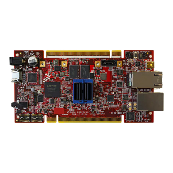
The following figures shows the main features of the
secondary and primary side of the TWR-LS1021A board.
© 2014 Freescale Semiconductor, Inc. All rights reserved.
NOTE
Document Number: TWR-LS1021AGS
Contents
1. Introduction . . . . . . . . . . . . . . . . . . . . . . . . . . . . . . . . . 1
1.1.Related documentation . . . . . . . . . . . . . . . . . . . . . . 2
2. Switches and jumpers configuration . . . . . . . . . . . . . . 3
3. Connecting USB UART . . . . . . . . . . . . . . . . . . . . . . . 6
4. Initial board power-up . . . . . . . . . . . . . . . . . . . . . . . . . 6
5. Board software configuration . . . . . . . . . . . . . . . . . . . 7
6. JTAG connectivity unit . . . . . . . . . . . . . . . . . . . . . . . . 8
6.1.Connecting JTAG using CodeWarrior TAP . . . . . . 9
6.2.Enabling CMSIS-DAP . . . . . . . . . . . . . . . . . . . . . . 9
7. TWR-LS1021A OOBE demo . . . . . . . . . . . . . . . . . . . 9
8. Revision History . . . . . . . . . . . . . . . . . . . . . . . . . . . . . 9
Rev. 1, 11/2014
Advertisement
Table of Contents

Subscribe to Our Youtube Channel
Related Manuals for Freescale Semiconductor TWR-LS1021A


Summary of Contents for Freescale Semiconductor TWR-LS1021A
-
Page 1: Table Of Contents
NOTE 7. TWR-LS1021A OOBE demo ....9 8. Revision History ......9... -
Page 2: Related Documentation
TWR-LS1021A board. Some of the documents listed below may be available only under a non-disclosure agreement (NDA). To request access to these documents, contact your local field applications engineer or sales representative. TWR-LS1021A Getting Started, Rev. 1 Freescale Semiconductor... -
Page 3: Switches And Jumpers Configuration
QorIQ Tower System. Switches and jumpers configuration The TWR-LS1021A board have two 8-way dual in line package (DIP) switch. The default DIP switch positions provide working set up values for the board. Check the default positions and verify the board is operational before changing the switches. - Page 4 00 = 66.66MHz setting 01 = 80.00MHz »10 = 100.00MHz (default) S3.4 CLKGEN_FS1 11 = 83.33MHz System clock frequency setting S3.5 NOR Bank Select BANK_SEL BANK_SEL » 0 : Vbank0 (default) 1 : Vbank1 TWR-LS1021A Getting Started, Rev. 1 Freescale Semiconductor...
- Page 5 Must be 1 [ON] Table 2-3 lists the jumper settings. Table 2-3. Jumper settings Setting Jumper UART1 console (default) LPUART1 console Others Jumpers Open Open Figure 4 shows the jumper settings. Figure 4. Jumper settings TWR-LS1021A Getting Started, Rev. 1 Freescale Semiconductor...
-
Page 6: Connecting Usb Uart
Flow Control: Hardware/None Then, select the first COM port assigned to the Virtual COM port. Initial board power-up The TWR-LS1021A board is powered through a barrel connector. This barrel should be supplied by a 5V @5A supply. See Figure NOTE It is normal for heatsink on the TWR-LS1021A board to become hot under standard operating conditions. -
Page 7: Board Software Configuration
No Link USB) Blink - Activity Board software configuration The NOR flash on TWR-LS1021A board is divided into two banks. There are different images in each banks that supports different functionality. NOTE TWR-LS1021A board comes pre-programmed with FLASH image. The bank0 is programmed with RCW support for QE, and the bank1 is programmed with the RCW support for 2D-ACE. -
Page 8: Jtag Connectivity Unit
TWR-LS1021A block diagram. Figure 6. TWR-LS1021A block diagram JTAG connectivity unit This section explains the following two method to configure the TWR-LS1021A board’s JTAG connectivity unit supported by CodeWarrior Development Studio for QorIQ LS series: TWR-LS1021A Getting Started, Rev. 1... -
Page 9: Connecting Jtag Using Codewarrior Tap
Connecting JTAG using CodeWarrior TAP To connect the JTAG using CodeWarrior TAP, perform these steps: 1. Connect the JTAG connectivity unit to the TWR-LS1021A JTAG connector J12. Pin 1 is marked on the board. 2. Switch ON the power to the board. - Page 10 Section 6.2, “Enabling CMSIS-DAP” Added as new sub-section to describe how to enable CMSIS-DAP support. Section 7, “TWR-LS1021A OOBE demo” Added as new section to introduce OOBE demo. Rev. 0 09/2014 Initial public release. TWR-LS1021A Getting Started, Rev. 1 Freescale Semiconductor...
- Page 11 Freescale, the Freescale logo, and QorIQ are trademarks of Freescale Semiconductor, Inc., Reg. U.S. Pat. & Tm. Off. Layerscape and QUICC Engine are trademarks of Freescale Semiconductor, Inc. All other product or service names are the property of their respective owners. ARM, Cortex, and TrustZone are registered trademarks of ARM Limited (or its subsidiaries) in the EU and/or elsewhere.
- Page 12 Mouser Electronics Authorized Distributor Click to View Pricing, Inventory, Delivery & Lifecycle Information: Freescale Semiconductor TWR-LS1021A...
Need help?
Do you have a question about the TWR-LS1021A and is the answer not in the manual?
Questions and answers