Table of Contents
Advertisement
Operation Manual
HRZ001-L
HRZ001-L1
HRZ001-L2
HRZ001-H
HRZ001-H1
HRZ002-W
HRZ010-WS
Save This Manual Carefully for Use at Any Time
Original Instructions
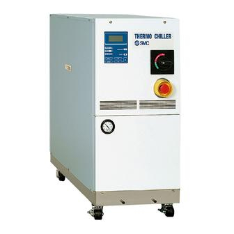
Thermo-Chiller
HRZ002-L
HRZ002-L1
HRZ002-L2
HRZ002-H
HRZ002-H1
HRZ008-W
HRZ010-W1S
HRZ004-L
HRZ004-L1
HRZ004-L2
HRZ004-H
HRZ004-H1
HRZ002-W1
HRZ010-W2S
© 2016 SMC CORPORATION All Rights Reserved
HRX-OM-I051-P
st
1
Edition:January.2005
th
17
Edition:Sep.2016
HRZ008-L
HRZ008-L1
HRZ008-L2
HRZ008-H
HRZ008-H1
HRZ008-W1
Advertisement
Table of Contents
Troubleshooting

Related Manuals for SMC Networks HRZ001-L


Summary of Contents for SMC Networks HRZ001-L
- Page 1 HRX-OM-I051-P Edition:January.2005 Edition:Sep.2016 Operation Manual Original Instructions Thermo-Chiller HRZ001-L HRZ002-L HRZ004-L HRZ008-L HRZ001-L1 HRZ002-L1 HRZ004-L1 HRZ008-L1 HRZ001-L2 HRZ002-L2 HRZ004-L2 HRZ008-L2 HRZ001-H HRZ002-H HRZ004-H HRZ008-H HRZ001-H1 HRZ002-H1 HRZ004-H1 HRZ008-H1 HRZ002-W HRZ008-W HRZ002-W1 HRZ008-W1 HRZ010-WS HRZ010-W1S HRZ010-W2S Save This Manual Carefully for Use at Any Time...
- Page 2 To the Customers Thank you for purchasing our THERMO CHILLER HRZ Series (hereinafter called “This system”). For the long-term, safe use of this system, be sure to read and understand this manual thoroughly before performing operation of this system. Warnings and precautions defined in this manual shall be observed. ...
-
Page 3: Table Of Contents
HRX-OM-I051 Table of Contents Table of Contents Chapter 1 Safety..................1-1 Before Using this System ..................1-1 Danger, Warning, and Caution Used in This Manual..........1-2 1.2.1 Hazard Levels ........................1-2 Definitions of “Serious injury” and “Minor injury” ..............1-2 1.2.2 1.2.3 Symbols .......................... - Page 4 HRX-OM-I051 Table of Contents 3.3.4 Wiring installation ......................... 3-8 3.3.5 Procedures for wiring installation ..................3-11 3.3.6 Installation of circulating fluid and facility water piping ............3-14 Chapter 4 System Startup and Shutdown ..........4-1 Pre-check ........................4-1 4.1.1 Installation condition ......................4-1 4.1.2 Cable connection .........................
- Page 5 HRX-OM-I051 Table of Contents Example 2: Communication mode is switched from “DIO REMOTE” to “LOCAL”.... 5-13 5.4.2 Example 3: Alarm signal of contact signal is changed from “N/A” to “ALARM1”....5-14 5.4.3 Chapter 6 Error Message and Troubleshooting ........6-1 Error Message ......................
- Page 6 HRX-OM-I051 Table of Contents HRZ Series TOC-4...
-
Page 7: Chapter 1 Safety
HRX-OM-I051 Chapter 1 Safety Chapter 1 Safety Be sure to read and understand the important precautions defined in this manual thoroughly prior to system use. 1.1 Before Using this System This "Safety" chapter describes the safety-related items that users should be and t aware of upon handling this system. -
Page 8: Danger, Warning, And Caution Used In This Manual
HRX-OM-I051 Chapter 1 Safety 1.2 Danger, Warning, and Caution Used in This Manual 1.2.1 Hazard Levels This system is designed with its first priority being the safety of workers and the prevention of system damage. This manual classifies the risks into the following three categories according to the severity and level of the hazard;... -
Page 9: Symbols
HRX-OM-I051 Chapter 1 Safety 1.2.3 Symbols This manual provides the following symbols in addition to “Danger”, “Warning”, and “Caution” to present the warning details in easy-to-understand manner. Symbol of electrical hazard This symbol warns you of potential electrical shock. ... -
Page 10: Hazard Warning Label
HRX-OM-I051 Chapter 1 Safety 1.3 Hazard Warning Label The hazard warning labels are applied to the sections of this system where potential hazards are present during system operation and maintenance. The hazard warning labels are in appropriate sizes and colors to get attention of the operator. -
Page 11: Location Of Hazard Warning Label
HRX-OM-I051 Chapter 1 Safety 1.3.2 Location of hazard warning label Do not peel off or deface the hazard warning labels. Confirm the locations of the hazard warning labels. Read the contents of the hazard warning labels carefully and keep them in mind. - Page 12 HRX-OM-I051 Chapter 1 Safety Hot/cold surface hazard Front Hazard warning label No.5 Rear Hazard warning label No.6 Figure 1-8 Hot/Cold Surface Hazard 1.3 Hazard Warning Label HRZ Series...
-
Page 13: Location Of Model Label
HRX-OM-I051 Chapter 1 Safety 1.4 Location of Model Label Information on your system such as Serial No. and Model No. need to be furnished when you contact the store you purchased from. Serial No. and model No. are listed on the label as shown below. Front Label Rear... -
Page 14: Safety Measures
HRX-OM-I051 Chapter 1 Safety 1.5 Safety Measures 1.5.1 Safety Precautions While this system is protected by various safety measures including the safety interlocks, the following basic safety precautions should be observed to assure further safe operations. Follow the following instructions upon operation of this system. Failure to follow the instructions can lead to personal injury or hazardous accidents. -
Page 15: Safety Interlock System
HRX-OM-I051 Chapter 1 Safety 1.5.2 Safety Interlock system Safety Interlock system The function of the safety interlock system is not only protect personnel by restricting operation that may cause damage to this system or the facility around it but also eliminate the danger relating to safety. This system is outfitted with several interlock functions that are activated when improper operation or hazardous conditions occur. -
Page 16: Lockout/Tagout
HRX-OM-I051 Chapter 1 Safety 1.5.3 Lockout/Tagout Summary Lockout in this system disables the main breaker operation to prevent electric shocks. Tagout, to be placed on a locked out main breaker, to prevent improper breaker operation (ON) conducted by other personnel. See “... - Page 17 HRX-OM-I051 Chapter 1 Safety Lockout procedure All service personnel must observe the restrictions applied during lockout and are required to perform lockout in accordance with this procedure. No service personnel is allowed to start, energize, or use the locked out system. Turn the breaker handle to ‘OFF ’.
-
Page 18: Protective Equipment
HRX-OM-I051 Chapter 1 Safety 1.5.4 Protective equipment This manual defines protective equipment according to work type. Wear proper protective equipment as shown below, according to work type. Read and understand the relevant operation manual thoroughly prior to use of protective equipment. ... -
Page 19: Emergency Measures
HRX-OM-I051 Chapter 1 Safety 1.6 Emergency Measures 1.6.1 Emergency off [EMO] switch Press the red emergency off [EMO] switch on the front of the system only if the need to shut off the power arises due to emergency such as natural disaster, fire, earthquake or personal injury. - Page 20 HRX-OM-I051 Chapter 1 Safety Reset of emergency off [EMO] switch No automatic recovery is applied to the emergency off [EMO] switch. Always eliminate the cause of activating the EMO before resetting. Potential serious accidents may occur if disregarded. Before restarting, always make sure that the cause of the emergency off condition (The reason why the EMO switch was activated) has been eliminated from the power supplies, the system and peripheral equipment.
-
Page 21: Waste Disposal
HRX-OM-I051 Chapter 1 Safety 1.7 Waste Disposal 1.7.1 Disposal of refrigerant and compressor oil HFC- refrigerant and compressor oil are present in this system. When recovering the refrigerant or compressor oil, the precautions provided below should thoroughly be read and understood in advance. If you have any questions or concerns, contact the system supplier. -
Page 22: Circulating Fluid Disposal
HRX-OM-I051 Chapter 1 Safety 1.7.2 Circulating fluid disposal As to the disposal of a circulating fluid (ethylene glycol solution, fluorinated fluid), consign the specialized industrial waste disposal agency with the contents detailed. 1.7.3 System disposal As to the disposal of this system, consign the specialized industrial waste disposal agency in accordance with local laws and regulations. -
Page 23: Chapter 2 Name Of Each Section
HRX-OM-I051 Chapter 2 Name of Each Section Chapter 2 Name of Each Section 2.1 Name of Each Section (1) HRZ001-L HRZ002-L HRZ004-L HRZ001-L1 HRZ002-L1 HRZ004-L1 HRZ001-L2 HRZ002-L2 HRZ004-L2 HRZ008-L2 HRZ001-H HRZ002-H HRZ004-H HRZ008-H HRZ001-H1 HRZ002-H1 HRZ004-H1 HRZ008-H1 HRZ002-W HRZ008-W HRZ002-W1... -
Page 24: Name Of Each Section (2)
HRX-OM-I051 Chapter 2 Name of Each Section 2.2 Name of Each Section (2) HRZ008-L HRZ008-L1 Operation display panel Main breaker Ventilating fan (exhaust side) Ventilating hole (intake side) Power cable access Emergency off [EMO] switch Refrigerant pressure gauge Circulating fluid fill port Facility water outlet Circulating fluid supply Facility water inlet... -
Page 25: Chapter 3 Transporting And Installation
HRX-OM-I051 Chapter 3 Transporting and Installation Chapter 3 Transporting and Installation Proper procedure must be followed when using this system. Exercise caution to assure personnel safety during the installation, operation, maintenance, and inspection of the system. Only personnel, who have adequate knowledge and experiences with not only this system but associated equipment are allowed to perform transport, installation, and maintenance involving potential hazardous task. -
Page 26: Transporting With Forklift
HRX-OM-I051 Chapter 3 Transporting and Installation 3.1.1 Transporting with forklift Do not set this system on its side for transportation. Potential damage to this system carrying danger of personnel injury if disregarded. Do not insert the fork from the back as well as front. ... -
Page 27: Transporting With Caster
HRX-OM-I051 Chapter 3 Transporting and Installation 3.1.2 Transporting with caster This system is heavy, which requires assistance for this work. Exercise caution and look out for sloped surfaces such as ramps, etc. Do not grab piping on the back of this system or panel handles when transporting with the casters. -
Page 28: Installation Conditions
HRX-OM-I051 Chapter 3 Transporting and Installation 3.2.1 Installation conditions System installation is not allowed outside or in the conditions described below. Potential system malfunction and damage may occur if disregarded. Clean room specifications are not applied to this unit. The pump and ventilating fan installed in this unit generate particles. -
Page 29: Installation Location And Maintenance Work Area
HRX-OM-I051 Chapter 3 Transporting and Installation 3.2.2 Installation location and maintenance work area This system does not have ventilating hole on the both right and left sides. Although this can be installed directly contacting to walls or devices, installation with maintenance space is recommended. -
Page 30: Procedure For Installation
System installation should be on a vibration-free stable level plane. See “Appendix 8.2 Outer Dimensions” in Chapter 8 on page 8-14 for the dimensions of this system. 3.3.2 Procedure for system securing (1) HRZ001-L HRZ002-L HRZ004-L HRZ001-L1 HRZ002-L1 HRZ004-L1... -
Page 31: Procedure For System Securing (2)
HRX-OM-I051 Chapter 3 Transporting and Installation 3.3.3 Procedure for system securing (2) HRZ008-L HRZ008-L1 Adjust and secure the adjustable feet of this system to secure the anti-seismic bracket. Transfer this system to the installation site. Adjust the adjustable foot with a 24-mm open end wrench. -
Page 32: Wiring Installation
Time Power cable The power cables are to be prepared under your responsibility, referring to the following table. Table 3-1 Power Cable and Main Breaker (This System) HRZ001-L HRZ001-L1 HRZ001-L2 HRZ002-L HRZ002-L1 HRZ002-L2... - Page 33 If the breaker with shorter operating time is connected, the customer’s equipment could be cut off du eto the inrush current of the motor of this product. HRZ001-L HRZ002-L HRZ004-L HRZ001-L1...
- Page 34 HRX-OM-I051 Chapter 3 Transporting and Installation HRZ008-L HRZ008-L1 30min 20min 14min 10min 6min 4min 2min 1min 0.5s 0.2s 0.1s 0.05s 0.02s 0.01s 100 135 300 400 500 600 700 1000 1500 2000 3000 4000 Current (% to the capacity of the main breaker of this product) Figure 3-7 Breaker operating characteristics curve HRZ010-WS HRZ010-W1S HRZ010-W2S 30min...
-
Page 35: Procedures For Wiring Installation
HRX-OM-I051 Chapter 3 Transporting and Installation 3.3.5 Procedures for wiring installation Be sure to turn OFF the factory side (primary side) power before connection to this system. Use the assigned procedure to peform lockout/tagout (Page 1-10). Turn OFF the power breaker on customer side (primary side), and then use the assigned procedures to peform lockout/tagout. - Page 36 HRX-OM-I051 Chapter 3 Transporting and Installation Loosen the cap and insert the power cable from the power cable access. Connect the communication cables with P1 and P2. P1 (D-sub 25P female) P2 (D-sub 9P female) P3 (D-sub 9P male) Not used. (Only for maintenance) Power cable Contact signal cable...
- Page 37 HRX-OM-I051 Chapter 3 Transporting and Installation Connect the power cables to the breaker terminal. Be sure to use a Phillips screwdriver. See Table 3-1 on Page 3-8 for recommended torque. Connect the grounding terminal (M8) of the power cable to the earth bar. Power cable Be sure to use a 13-mm open end wrench.
- Page 38 HRX-OM-I051 Chapter 3 Transporting and Installation 3.3.6 Installation of circulating fluid and facility water piping Choose proper external piping with consideration for pressure, temperature and compatibility with the circulating fluid. Potential pipe rupture during operation may occur if disregarded. ...
- Page 39 HRX-OM-I051 Chapter 3 Transporting and Installation Procedure for piping installation Secure the pipe coupling section with a pipe wrench, and provide proper tightening to the pipe. Pipe coupling section Figure 3-12 Pipe Tightening Recommended piping installation Circulating fluid supply System on the customer side Circulating fluid return...
- Page 40 HRX-OM-I051 Chapter 3 Transporting and Installation 3.3 Procedure for Installation HRZ Series 3-16...
-
Page 41: Installation Of Circulating Fluid And Facility Water Piping
HRX-OM-I051 Chapter 4 System Startup and Shutdown Chapter 4 System Startup and Shutdown Only personnel, who have adequate knowledge of and experiences with not only this system but associated equipment, are allowed to implement system startup and shutdown. 4.1 Pre-check Check the following items prior to starting up the system. -
Page 42: Supply Of Circulating Fluid
HRX-OM-I051 Chapter 4 System Startup and Shutdown 4.3 Supply of Circulating Fluid Circulating fluids to use vary with system models. See section 8.1.1 “System specification” in Chapter 8 for the designated circulating fluid for a specific model. Circulating fluid fill port Circulating fluid Circulating fluid level gauge specified level... -
Page 43: Supply Of Circulating Fluid
HRX-OM-I051 Chapter 4 System Startup and Shutdown 4.3.2 Supply of circulating fluid Remove the circulating fluid fill cap, and fill the circulating fluid until it reaches its specified level. The circulating fluid specified level is a range between “HIGH” and “LOW” in Figure 4-1. -
Page 44: Requirement For System Startup
HRX-OM-I051 Chapter 4 System Startup and Shutdown 4.4 Requirement for System Startup 4.4.1 Turning ON power Make sure that the main breaker for this system is OFF, and release lockout/tagout of the power breaker on customer side (primary side). Then, turn ON the power. Turn ON the main breaker of this system. -
Page 45: Circulating Fluid Temperature Setting
HRX-OM-I051 Chapter 4 System Startup and Shutdown 4.4.2 Circulating fluid temperature setting From the “Setting screen” on the LCD screen, set the circulating fluid at any temperature. See section 5.4 “Examples of System Operation” in “Chapter 5 System Operation” on page 5-11 for operating procedure. [Tips] See section 8.1.1 “System specification”... - Page 46 HRX-OM-I051 Chapter 4 System Startup and Shutdown 4.5 System Startup and Shutdown HRZ Series...
-
Page 47: Chapter 5 System Operation
HRX-OM-I051 Chapter 5 System Operation Chapter 5 System Operation 5.1 Operation Display Panel Use the operation display panel located in front of the system for the basic operations. “LCD screen” “REMOTE” lamp This comes on when the system is in remote mode. [START/STOP] key Used to start and stop the operation. -
Page 48: Flow Chart Of Operation Screen
HRX-OM-I051 Chapter 5 System Operation 5.2 Flow Chart of Operation Screen Figure 5-2 Flow Chart of Operation Screen [Tips] With the press of the [SEL] key, the screen is switched to the “Menu screen 1” regardless of the screen status. Table 5-1 Descriptions of Operation Screens Screen Descriptions... -
Page 49: Operation Screen
HRX-OM-I051 Chapter 5 System Operation 5.3 Operation Screen 5.3.1 Model Indication screen Figure 5-3 Model Indication Screen The “Model Indication screen” is displayed upon power-ON of this system. This screen remains ON for approx. 20 seconds and is automatically switched to the “Status screen 1”. The “Alarm Display screen”... -
Page 50: Status Screen 2
HRX-OM-I051 Chapter 5 System Operation 5.3.3 Status screen 2 Figure 5-5 Status Screen 2 Table 5-4 Status Screen 2 Item Descriptions Discharge temperature of the circulating fluid TEMP PV (A value derived according to the offset if applied) TEMP SP Set circulating fluid temperature OFFSET Set offset... -
Page 51: Status Screen 4
HRX-OM-I051 Chapter 5 System Operation 5.3.5 Status screen 4 Figure 5-7 Status Screen 4 Table 5-6 Status Screen 4 Item Descriptions TEMP PV Discharge temperature of the circulating fluid TEMP SP Set circulating fluid temperature Displays the BAND/READY [Displayed when set value <<TEMP READY>>... -
Page 52: Setting Screen
HRX-OM-I051 Chapter 5 System Operation 5.3.7 Setting screen Figure 5-9 Setting Screen This screen enables the setting of TEMP SP value. Not available if the communication mode is in “SER REMOTE” Table 5-8 Setting Screen Item Setting range HRZ□□□-L□ : -20.0 to 40.0°C HRZ□□□-L2 : 10.0 to 40.0°C TEMP SP... -
Page 53: Mode Selection Screen
HRX-OM-I051 Chapter 5 System Operation 5.3.8 Mode Selection screen Figure 5-10 Mode Selection Screen This screen enables the selection of the communication mode. The procedures for system start/stop and TEMP SP value setting may vary with the communication mode. Other operations and settings are available only from the operation display panel. Table 5-9 Mode Selection Screen Item Setting... - Page 54 HRX-OM-I051 Chapter 5 System Operation This screen enables the setting of set values. Table 5-10 Initial Setting Screen Item Setting range Descriptions TEMP BAND 1.0 to 5.0°C Allows the selection of the band width for TEMP SP. Allows the setting of the time from TEMP PV value TEMP 10 to 480sec reaching BAND range to TEMP READY is displayed...
-
Page 55: Maintenance Screen
HRX-OM-I051 Chapter 5 System Operation 5.3.10 Maintenance screen Figure 5-12 Maintenance Screen Table 5-11 Maintenance Screen Item Setting OPEN The solenoid valve is opened forcefully. VALVE CLOSE The solenoid valve is closed forcefully. [Tips] Available only if a solenoid value (optional for DI control kit) is provided. 5.3.11 Option screen Figure 5-13 Option Screen Table 5-12 Option Screen... -
Page 56: Alarm Display Screen
HRX-OM-I051 Chapter 5 System Operation 5.3.12 Alarm Display screen Figure 5-14 Alarm Display Screen In the event of an error in this system, the current screen is switched to the Alarm Display screen to display the relevant alarm code. and message. The Alarm Display screen is displayed only if an error is raised. -
Page 57: Examples Of System Operation
HRX-OM-I051 Chapter 5 System Operation 5.4 Examples of System Operation 5.4.1 Example 1: Circulating fluid set temperature is changed from 23.0°C to 34.1°C. Figure 5-16 Change of Set Temperature from 25.0°C to 34.1°C Press the [SEL] key to display the “Menu screen 1”. - Page 58 HRX-OM-I051 Chapter 5 System Operation Use the arrow keys ([▲], [▼], [ ]) to change the temperature to 34.1°C. [▲] key: Used to add one value on which the cursor is placed. [▼] key: Used to subtract one value on which the cursor is placed.
-
Page 59: Example 2: Communication Mode Is Switched From "Dio Remote" To "Local
HRX-OM-I051 Chapter 5 System Operation Example 2: Communication mode is switched from “DIO 5.4.2 REMOTE” to “LOCAL”. Figure 5-22 Switching of Communication Mode from “DIO REMOTE” to “LOCAL” Press the [SEL] key to display the “Menu screen 1”. Figure 5-23 Menu Screen 1 With the use of the arrow keys ([▲], [▼]), move the cursor to “2. -
Page 60: Example 3: Alarm Signal Of Contact Signal Is Changed From "N/A" To "Alarm1
HRX-OM-I051 Chapter 5 System Operation 5.4.3 Example 3: Alarm signal of contact signal is changed from “N/A” to “ALARM1”. Figure 5-27 Change of Alarm Signal of Contact signal from “N/A” to “ALARM1” Press the [SEL] key to display the “Menu screen 1”. - Page 61 HRX-OM-I051 Chapter 5 System Operation Use the arrow keys ([▲], [▼]) to select “ALARM1”. Figure 5-32 Initial Setting Screen 3: ALARM1 Press the [ENT] key. “OUT” flashes again, and the selection takes effect. Figure 5-33 Initial Setting Screen 3: Setting Confirmation (OUT) [Tips] To cancel a selection, press the [SEL] key, not [ENT] key.
- Page 62 HRX-OM-I051 Chapter 5 System Operation 5.4 Examples of System Operation HRZ Series 5-16...
-
Page 63: Chapter 6 Error Message And Troubleshooting
HRX-OM-I051 Chapter 6 Error Message and Troubleshooting Chapter 6 Error Message and Troubleshooting 6.1 Error Message The following are to be performed in the event of an error in this system. The “ALARM” lamp comes on. Alarm buzzer comes on. ... -
Page 64: Troubleshooting
HRX-OM-I051 Chapter 6 Error Message and Troubleshooting 6.2 Troubleshooting The procedure for error recovery varies with alarm types. Alarm Code.01 to 20, 22, 24, 25: Eliminate the error cause. Press the [RESET] key on the operation display panel or power cycle the main breaker to enable error recovery to take effect. ... - Page 65 HRX-OM-I051 Chapter 6 Error Message and Troubleshooting Table 6-1 Troubleshooting (2/2) System Code Error message Cause Remedies condition Check that the external valve is opened. Return Low Flow The flow rate of the circulating Stop fluid falls short of 6L/min. Prepare a thicker external pipe or install bypass piping.
- Page 66 HRX-OM-I051 Chapter 6 Error Message and Troubleshooting 6.2 Troubleshooting HRZ Series...
-
Page 67: Chapter 7 System Maintenance
HRX-OM-I051 Chapter 7 System Maintenance Chapter 7 System Maintenance 7.1 Water Quality Management Only designated circulating fluid is permitted to use for this system. Potential system failure and fluid leak may occur if disregarded, which results in electric shock, ground fault, and freeze. Be sure to use fresh water (tap water) compliant with water quality standards in the table below for ethylene glycol aqueous solution and facility water. -
Page 68: Inspection And Cleaning
HRX-OM-I051 Chapter 7 System Maintenance 7.2 Inspection and Cleaning Do not touch any electrical parts with wet hands. Keep wet hands away from electrical parts. Potential electric shock can occur if disregarded. Keep this system from water. Potential electric shock or fire can occur if disregarded. -
Page 69: Quarterly Inspection
HRX-OM-I051 Chapter 7 System Maintenance 7.2.2 Quarterly inspection Quarterly inspection requires an advance lockout/tagout of this system. See section 1.5.3 “Lockout/Tagout” in “Chapter 1 Safety” for details. Table 7-3 Quarterly Inspection Inspection item Inspection method Circulating fluid is to be drained for check. Fluid should be free of particles, moisture and foreign substances. -
Page 70: Draining Of Circulating Fluid Out Of Tank
HRX-OM-I051 Chapter 7 System Maintenance 7.3.1 Draining of circulating fluid out of tank Use the clean container for circulating fluid recovery. Reuse of the recovered circulating fluid with contaminated will cause insufficient cooling and system failure Be sure to wait until the circulating fluid obtains room temperature for its draining. -
Page 71: Draining Of Facility Water
HRX-OM-I051 Chapter 7 System Maintenance Upon completion of fluid draining, close the valves of the main and sub tank drain ports. Add plugs to seal off ports on the rear of Circulating fluid return this system. See section 7.3.2 “Draining of facility water” Facility water outlet for plug attachment. -
Page 72: Periodic Replacement Parts
HRX-OM-I051 Chapter 7 System Maintenance Remove facility water piping. Remove the joints such as unions if present. Drain the facility water using the facility water inlet port. 7.4 Periodic Replacement Parts Replacement of consumables listed in the following table is recommended. Contact the system supplier for request of part replacement. -
Page 73: Chapter 8 Appendix
Chapter 8 Appendix Chapter 8 Appendix 8.1 Specification 8.1.1 System specification Specification for fluorinated fluid (low temperature) Table 8-1 Specification for Fluorinated Fluid (Low Temperature) Model HRZ001-L HRZ002-L HRZ004-L HRZ008-L Cooling method Water cooled refrigerant Cooling capacity 1.0 (At -10°C) 2.0 (At -10°C) - Page 74 HRX-OM-I051 Chapter 8 Appendix Specification for fluorinated fluid (high temperature) Table 8-2 Specification for Fluorinated Fluid (High Temperature) Model HRZ001-H HRZ002-H HRZ004-H HRZ008-H Cooling method Water cooled refrigerant Cooling capacity 1.0 (At 20°C) 2.0 (At 20°C) 4.0 (At 20°C) 8.0 (At 20°C) (50Hz/60Hz) Operating temperature range...
- Page 75 HRX-OM-I051 Chapter 8 Appendix Specification for fluorinated fluid (wide temperature) Table 8-3 Specification for Fluorinated Fluid (Wide Temperature) Model HRZ002-W HRZ008-W Cooling method Water cooled refrigerant Cooling capacity 2.0 (At 20°C) 8.0 (At 20°C) (50Hz/60Hz) Operating temperature range °C -20 to 90 Temperature stability °C...
- Page 76 HRX-OM-I051 Chapter 8 Appendix Specification for ethylene glycol solution (low temperature) Table 8-4 Specification for Ethylene Glycol Aqueous Solution (Low Temperature) Model HRZ001-L1 HRZ002-L1 HRZ004-L1 HRZ008-L1 Cooling method Water cooled refrigerant Cooling capacity 1.0 (At -10°C) 2.0 (At -10°C) 4.0 (At -10°C) 8.0 (At -10°C) (50Hz/60Hz)
- Page 77 HRX-OM-I051 Chapter 8 Appendix Specification for ethylene glycol solution (high temperature) Table 8-5 Specification for Ethylene Glycol Aqueous Solution (High Temperature) Model HRZ001-H1 HRZ002-H1 HRZ004-H1 HRZ008-H1 Cooling method Water cooled refrigerant Cooling capacity 1.0 (At 20°C) 2.0 (At 20°C) 4.0 (At 20°C) 8.0 (At 20°C) (50Hz/60Hz)
- Page 78 HRX-OM-I051 Chapter 8 Appendix Specification for ethylene glycol solution (wide temperature) Table 8-6 Specification for Ethylene Glycol Aqueous Solution (Wide Temperature) Model HRZ002-W1 HRZ008-W1 Cooling method Water cooled refrigerant Cooling capacity 2.0 (At 20°C) 8.0 (At 20°C) (50Hz/60Hz) Operating temperature range °C -20 to 90 Temperature stability...
- Page 79 HRX-OM-I051 Chapter 8 Appendix Specification for water (low temperature) Table 8-7 Specification for water (Low Temperature) Model HRZ001-L2 HRZ002-L2 HRZ004-L2 HRZ008-L2 Cooling method Water cooled refrigerant Cooling capacity 1.0 (At 20°C) 2.0 (At 20°C) 4.0 (At 20°C) 8.0 (At 20°C) (50Hz/60Hz) Operating temperature range °C...
- Page 80 HRX-OM-I051 Chapter 8 Appendix Specification for fluorinated fluid (wide temperature with Inverter) Table 8-8 Specification for Fluorinated Fluid (Wide Temperature with Inverter) Model HRZ010-WS Cooling method Water cooled refrigerant Cooling capacity 10.0 (At 20°C) (50Hz/60Hz) Operating temperature range °C -20 to 90 Temperature stability °C...
- Page 81 HRX-OM-I051 Chapter 8 Appendix Specification for ethylene glycol solution (low temperature with Inverter) Table 8-9 Specification for ethylene glycol solution (low temperature with Inverter) Model HRZ010-W1S Cooling method Water cooled refrigerant Cooling capacity 10.0 (At 20°C) (50Hz/60Hz) Operating temperature range °C -20 to 90 Temperature stability...
- Page 82 HRX-OM-I051 Chapter 8 Appendix Specification for water (low temperature with Inverter) Table 8-10 Specification for water (low temperature with Inverter) Model HRZ010-W2S Cooling method Water cooled refrigerant Cooling capacity 9.0 (At 20°C) (50Hz/60Hz) Operating temperature range °C 10 to 60 Temperature stability °C ±0.1...
-
Page 83: Communication Specification
HRX-OM-I051 Chapter 8 Appendix 8.1.2 Communication specification This section provides the general outline of communications utilized in this system. For detail specification, we provide a separate system manual “Communication Specification”, which is available through your local distributor. Contact signal Table 8-11 Contact Signal Item Specification... - Page 84 HRX-OM-I051 Chapter 8 Appendix Serial RS-485 Table 8-12 Serial RS-485 Item Specification Connector No. Connector type (this system) D-sub9P female connector Standard EIA RS485 Protocol Modicon Modbus This system Your system Circuit block diagram Internal circuit 8.1 Specification HRZ Series 8-12...
-
Page 85: Alarm Signal Selection
HRX-OM-I051 Chapter 8 Appendix 8.1.3 Alarm signal selection User can designate one alarm signal for contact signal. See section 5.3.9 “Initial Setting screen” for signal selecting. The following table presents the setting-alarm relationship. The alarm signal is turned OFF if the designated alarm detected. (Alarm signal is ON if no alarm is detected.) Table 8-13 Alarm signal selection Setting... -
Page 86: Outer Dimensions
HRX-OM-I051 Chapter 8 Appendix 8.2 Outer Dimensions 8.2.1 Part 1 HRZ001-H HRZ001-H1 HRZ002-H HRZ002-H1 Back Front Figure 8-1 Outer Dimensions 8.2.2 Part 2 HRZ001-L HRZ002-L HRZ004-L HRZ008-L2 HRZ001-L1 HRZ002-L1 HRZ004-L1 HRZ008-H HRZ001-L2 HRZ002-L2 HRZ004-L2 HRZ008-H1 HRZ002-W HRZ004-H HRZ008-W HRZ002-W1 HRZ004-H1... - Page 87 HRX-OM-I051 Chapter 8 Appendix 8.2.3 Part 3 HRZ008-L HRZ008-L1 Back Left Front Figure 8-3 Outer Dimensions HRZ Series 8.2 Outer Dimensions 8-15...
-
Page 88: Flow Chart
HRX-OM-I051 Chapter 8 Appendix 8.3 Flow Chart 8.3.1 Part 1 HRZ001-H HRZ002-H HRZ004-H HRZ008-H HRZ001-H1 HRZ002-H1 HRZ004-H1 HRZ008-H1 HRZ002-W HRZ008-W HRZ002-W1 HRZ008-W1 HRZ010-WS HRZ010-W1S HRZ010-W2S *1 : For HRZ001-H* and HRZ002-H* , electron Refrigerating circuit expansion valve is thermo static expansion valve. Electron expansion valve... -
Page 89: Part 2
HRX-OM-I051 Chapter 8 Appendix 8.3.2 Part 2 HRZ001-L HRZ002-L HRZ004-L HRZ008-L HRZ001-L1 HRZ002-L1 HRZ004-L1 HRZ008-L1 HRZ001-L2 HRZ002-L2 HRZ004-L2 HRZ008-L2 Refrigerating circuit *1 : For HRZ004-L* and HRZ008-L*, electron expansion valve is thermo static expansion valve Electron expansion Electron valve expansion... -
Page 90: Offset Function
HRX-OM-I051 Chapter 8 Appendix 8.4 Offset Function Potential deviations in temperature between this system and your system may be concerned depending on the installation environment. The offset function falling into three types (MODE1 to 3) is assigned to calibrate deviations in temperature. See the following descriptions for the offset function. -
Page 91: Example Of Offset Function
HRX-OM-I051 Chapter 8 Appendix 8.4.1 Example of offset function When the discharge temperature of the circulating fluid is at 30°C, heat is dissipated by 1°C to allow the circulating fluid in your system to be 29°C. Under the above condition, the following process is to be performed with the utilization of MODEs 1 to 3. - Page 92 HRX-OM-I051 Chapter 8 Appendix When MODE2 is selected With OFFSET value set at -1°C, TEMP PV and communication data express “29°C” (circulating fluid discharge temp. value + OFFSET value) that agrees with the temperature of the circulating fluid in your system. This system Your system Communication data...
-
Page 93: Band/Ready Function
HRX-OM-I051 Chapter 8 Appendix 8.5 BAND/READY function Sets BAND to TEMP SP value, and notifies TEMP PV value reaches within BAND range by the operation display panel or the communication. See section “5.3.9 Initial Setting screen” on page 5-7, “5.3.11 Option screen” on page 5-9 for the procedure of the setting. -
Page 94: Anchor Bolt Mounting Position
HRX-OM-I051 Chapter 8 Appendix 8.6 Anchor Bolt Mounting Position 8.6.1 Part 1 HRZ001-L HRZ002-L HRZ004-L HRZ001-L1 HRZ002-L1 HRZ004-L1 HRZ001-L2 HRZ002-L2 HRZ004-L2 HRZ008-L2 HRZ001-H HRZ002-H HRZ004-H HRZ008-H HRZ001-H1 HRZ002-H1 HRZ004-H1 HRZ008-H1 HRZ002-W HRZ008-W HRZ002-W1 HRZ008-W1 HRZ010-WS HRZ010-W1S HRZ010-W2S Lock the brakes on casters (2 pcs. on the front), and attach the anti-seismic bracket (optional: HRZ-TK002) to secure this system. -
Page 95: Part 2
HRX-OM-I051 Chapter 8 Appendix 8.6.2 Part 2 HRZ008-L HRZ008-L1 Adjust and secure the adjuster foot of this system to secure the anti-seismic bracket. Anti-seismic bracket is an accessory, which is required for the installation of this system. It is your responsibility to prepare anchor bolts suitable for your floor material. -
Page 96: Compliance
HRX-OM-I051 Chapter 8 Appendix 8.7 Compliance This system conforms to the following standards. Table 8-14 Compliance EMC Directive 2004/108/EC Low Voltage 2006/95/EC CE Marking Directive Machinery 2006/42/EC Directive SEMATECH S2-93, S8-95 SEMI S2-0703, S8-0701, F47-0200 E229305 / UL1995 8.7 Compliance HRZ Series 8-24... -
Page 97: Thermo Chiller Daily Inspection Sheet
HRX-OM-I051 Chapter 8 Appendix Thermo Chiller Daily Inspection Sheet HRZ Series 8.8 Thermo Chiller Daily Inspection Sheet 8-25... - Page 98 Product Warranty 1. Warranty If a failure is observed in our Thermo Chiller, repair shall be provided in accordance with the warranty period and preconditions defined below at SMC’s option. Repair involves the inspection and/or replacement and/or modification of a defective part. Removed parts shall become the possession of SMC.
Need help?
Do you have a question about the HRZ001-L and is the answer not in the manual?
Questions and answers
eror cod: 31 no safety signal flt