
Subscribe to Our Youtube Channel
Related Manuals for SMC Networks HRZC010-WS


Summary of Contents for SMC Networks HRZC010-WS
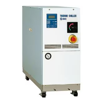
- Page 1 DOC1065036 Original Instructions PRODUCT NAME Thermo Chiller MODEL / Series / Product Number HRZC010-WS HRZC010-W1S...
- Page 2 To the Customers Thank you for purchasing our THERMO CHILLER HRZC Series (hereinafter called “This product”). For the long-term, safe use of this product, be sure to read and understand this manual thoroughly before performing operation of product. ⚫ Warnings and precautions defined in this manual shall be observed. ⚫...
-
Page 3: Table Of Contents
DOC1065036 Table of Contents Table of Contents Chapter 1 Safety..................1-1 Before Using This Product ..................1-1 Danger, Warning, and Caution Used in This Manual..........1-2 1.2.1 Hazard levels ........................1-2 1.2.2 Definitions of “Serious injury” and “Minor injury” ..............1-2 1.2.3 Symbols .......................... - Page 4 DOC1065036 Table of Contents Chapter 4 System Startup and Shutdown ..........4-1 Pre-check ........................4-1 4.1.1 Installation condition ......................4-1 4.1.2 Cable connection ......................... 4-1 4.1.3 Installation of circulating fluid and facility water piping ............4-1 4.1.4 Operating signal from your system ..................4-1 4.1.5 Check emergency off [EMO] switch ..................
- Page 5 DOC1065036 Table of Contents 5.3.19 Initial Setting screen 4 ....................... 5-21 5.3.20 Initial Setting screen 5 ....................... 5-22 5.3.21 Initial Setting screen 6 ....................... 5-23 5.3.22 Initial Setting screen 7 ....................... 5-24 5.3.23 Initial Setting screen 8 ....................... 5-25 5.3.24 Mode Selection screen ......................
- Page 6 DOC1065036 Table of Contents 8.1.6 Alarm signal selection ......................8-9 Outer Dimensions ....................8-10 Flow Chart ......................8-11 Offset Function ...................... 8-12 8.4.1 Example of offset function ....................8-13 BAND/READY Function ..................8-15 Anchor Bolt Mounting Position ................8-16 Compliance ......................8-17 Thermo Chiller Daily Inspection Sheet ..............
-
Page 7: Chapter 1 Safety
DOC1065036 Chapter 1 Safety Chapter 1 Safety Be sure to read and understand the important precautions defined in this manual thoroughly prior to system use. 1.1 Before Using This Product ⚫ This "Safety" chapter describes the safety-related items that users should be aware of upon handling this product. -
Page 8: Danger, Warning, And Caution Used In This Manual
DOC1065036 Chapter 1 Safety 1.2 Danger, Warning, and Caution Used in This Manual 1.2.1 Hazard Levels This product is designed with its first priority being the safety of workers and the prevention of system damage. This manual classifies the risks into the following three categories according to the severity and level of the hazard: Danger, Warning, and Caution. -
Page 9: Symbols
DOC1065036 Chapter 1 Safety 1.2.3 Symbols This manual provides the following symbols in addition to “Danger”, “Warning”, and “Caution” to present the warning details in easy-to- understand manner. ◼ Symbol of electrical hazard This symbol warns you of potential electrical shock. ◼... -
Page 10: Hazard Warning Labels
DOC1065036 Chapter 1 Safety 1.3 Hazard Warning Label The hazard warning labels are applied to the sections of this product where potential hazards are present during system operation and maintenance. The hazard warning labels are in appropriate sizes and colors to get attention of the operator. - Page 11 DOC1065036 Chapter 1 Safety ◼ Labels of high pressure refrigerant hazard [High pressure refrigerant hazard] The system contains refrigerant under high pressure. Do not tamper with the system. It must be serviced by suitably qualified persons only. Figure 1-7 Hazard warning label No.7 Figure 1-8 Hazard warning label No.8 HRZC Series 1.3 Hazard Warning Label...
-
Page 12: Location Of Hazard Warning Labels
DOC1065036 Chapter 1 Safety 1.3.2 Location of hazard warning label Do not peel off or deface the hazard warning labels. ⚫ Confirm the locations of the hazard warning labels. ⚫ Read the contents of the hazard warning labels carefully and keep them in mind. - Page 13 DOC1065036 Chapter 1 Safety ◼ Hot/cold surface hazard Front Hazard warning label No.5 Rear Hazard warning label No.6 Figure 1-10 Hot/Cold Surface Hazard HRZC Series 1.3 Hazard Warning Label...
- Page 14 DOC1065036 Chapter 1 Safety ◼ High pressure refrigerant hazard Hazard warning label No.8 Front Hazard warning label No.7 Figure 1-11 High pressure refrigerant hazard 1.3 Hazard Warning Label HRZC Series...
-
Page 15: Location Of Model Label
DOC1065036 Chapter 1 Safety 1.4 Location of Model Label Information about the product, such as Serial No. and Model No. can be found on the product label. This information is needed when contacting an SMC sales distributor. Model Serial Figure 1-12 Location of Model Label HRZC Series 1.4 Location of Model Label... -
Page 16: Safety Measures
DOC1065036 Chapter 1 Safety 1.5 Safety Measures 1.5.1 Safety precautions While this product is protected by various safety measures including the safety interlocks, the following basic safety precautions should be observed to assure further safe operations. Follow the instructions below upon operation of this system. Failure to follow the instructions can lead to personal injury or hazardous accidents. -
Page 17: Safety Interlock System
DOC1065036 Chapter 1 Safety 1.5.2 Safety Interlock system ◼ Safety Interlock system The function of the safety interlock system is not only to protect personnel by restricting operation that may cause damage to this product or the facility around it, but also to eliminate the danger relating to safety. This product is outfitted with several interlock functions that are activated when improper operation or hazardous conditions occur. -
Page 18: Lockout/Tagout
DOC1065036 Chapter 1 Safety 1.5.3 Lockout/Tagout ◼ Summary Lockout in this product disables the main breaker operation to prevent electric shocks. Tagout, to be placed on a locked out main breaker, to prevent improper breaker operation (ON) conducted by other personnel. See “Lockout procedure”... -
Page 19: Lockout Procedure
DOC1065036 Chapter 1 Safety ◼ Lockout procedure All service personnel must observe the restrictions applied during lockout and are required to perform lockout in accordance with this procedure. No service personnel is allowed to start, energize, or use the locked out system. Turn the breaker handle to ‘OFF ’. -
Page 20: Protective Equipment
DOC1065036 Chapter 1 Safety 1.5.4 Protective equipment This manual defines protective equipment according to work type. Wear proper protective equipment as shown below, according to work type. Read and understand the relevant operation manual thoroughly prior to use of protective equipment. ◼... -
Page 21: Emergency Measures
DOC1065036 Chapter 1 Safety 1.6 Emergency Measures 1.6.1 Emergency off [EMO] switch Press the red EMO switch on the front of the system only if the need to shut off the power arises due to emergency such as natural disaster, fire, earthquake, or personal injury. - Page 22 DOC1065036 Chapter 1 Safety ◼ Reset of emergency off [EMO] switch No automatic recovery is applied to the emergency off [EMO] switch. Always eliminate the cause of activating the EMO before resetting. Potential serious accidents may occur if disregarded. Before restarting, always make sure that the cause of the emergency off condition (The reason why the EMO switch was activated) has been eliminated from the power supplies, the product, and peripheral equipment.
-
Page 23: Waste Disposal
DOC1065036 Chapter 1 Safety 1.7 Waste Disposal 1.7.1 Disposal of compressor oil The product uses compressor oil. If they need to be recovered, read and understand the instructions below carefully. If there is any unclear point, contact an SMC's sales distributor. Only service personnel or those who are qualified are allowed to open the panel of this system. -
Page 24: Circulating Fluid Disposal
DOC1065036 Chapter 1 Safety 1.7.2 Circulating fluid disposal The disposal of the circulating fluid (ethylene glycol solution, fluorinated fluid) must be handled by a specialized industrial waste disposal agency with the contents detailed. 1.7.3 System disposal The disposal of the product must be handled by a specialized industrial waste disposal agency in accordance with local laws and regulations. -
Page 25: Chapter 2 Name Of Each Section
DOC1065036 Chapter 2 Name of Each Section Chapter 2 Name of Each Section 2.1 Name of Each Section Operation display panel Main breaker Ventilating fan (exhaust side) Power cable access Circulating fluid fill port Ventilating hole (intake side) Emergency off [EMO] switch Facility water outlet port Facility water inlet port Circulating fluid return port... -
Page 27: Chapter 3 Transporting And Installation
DOC1065036 Chapter 3 Transporting and Installation Chapter 3 Transporting and Installation Proper procedure must be followed when using this system. Exercise caution to assure personnel safety during the installation, operation, maintenance, and inspection of the system. Only personnel, who have adequate knowledge and experiences with not only this system but associated equipment, are allowed to perform transport, installation, and maintenance involving potential hazardous task. -
Page 28: Transporting With Forklift
DOC1065036 Chapter 3 Transporting and Installation 3.1.1 Transporting with forklift ⚫ Do not set this system on its side for transportation. If disregarded, there is potential damage to the system, damage to the forklift, and danger of injury to personnel. ⚫... -
Page 29: Transporting With Caster
DOC1065036 Chapter 3 Transporting and Installation 3.1.2 Transporting with caster This product is heavy, which requires assistance for this work. Exercise caution and look out for sloped surfaces such as ramps, etc. Do not grab piping on the back of this product or panel handles when transporting with the casters. -
Page 30: Installation Conditions
DOC1065036 Chapter 3 Transporting and Installation 3.2.1 Installation conditions The product installation is not allowed outside or in the conditions described below. Potential system malfunction and damage may occur if disregarded. Clean room specifications are not applied to this product. The pump and ventilating fan installed in this product generate particles. -
Page 31: Installation Location And Maintenance Work Area
DOC1065036 Chapter 3 Transporting and Installation 3.2.2 Installation location and maintenance work area This product does not have ventilating holes on the right and left sides. Although this can be installed directly contacting to walls or devices, installation with maintenance space is recommended. -
Page 32: Procedure For Installation
DOC1065036 Chapter 3 Transporting and Installation 3.3 Procedure for Installation ⚫ Anti-quake bracket is an optional part, which is required for the installation of this system (HRZ-TK002). ⚫ Preparation of anchor bolts suitable for floor material is your responsibility. M12-anchor bolts (4 pcs.) needed. See “Appendix 8.6 Anchor Bolt Mounting Position ”on page 8-16. -
Page 33: Wiring Installation
Voltage rise % Time ◼ Power cable The power cables are to be prepared under your responsibility, referring to the following table. Table 3-1 Power Cable and Main Breaker (This product) HRZC010-WS Item HRZC010-W1S Size (recommended) 10AWG4-conductor Breaker R5.5-8... - Page 34 DOC1065036 Chapter 3 Transporting and Installation ◼ Selection of the breaker for the customer’s equipment (primary side) This product is equipped with the breaker which has different operating characteristics depending on each model. For the customer’s equipment (primary side), use the breaker whose operating time is equal to or longer than the breaker of this product.
-
Page 35: Procedures For Wiring Installation
DOC1065036 Chapter 3 Transporting and Installation 3.3.4 Procedures for wiring installation Be sure to turn OFF the factory side (primary side) power before connection to this product. Use the assigned procedure to peform lockout/tagout (Page 1-12). Turn OFF the power breaker on customer side (primary side), and then use the assigned procedures to peform lockout/tagout. - Page 36 DOC1065036 Chapter 3 Transporting and Installation Loosen the cap at power cable access (strain relief) and insert the power cable. Power cable Figure 3-7 Power cable insertion Correct phase rotation is required when attach the power cable to the breaker terminal. Do not drop a screw or washer in the electrical unit when attaching the breaker cover and terminal.
- Page 37 DOC1065036 Chapter 3 Transporting and Installation Connect the power cables to the breaker terminal. Be sure to use a Phillips screwdriver. See Table 3-1 on Page 3-7 for recommended torque. Connect the grounding terminal (M8) of the power cable to the earth bar. Power cable Be sure to use a 13-mm open end wrench.
- Page 38 DOC1065036 Chapter 3 Transporting and Installation Connect the communication cables with P1 and P2. P2 (D-sub 9P female) Serial RS-485 communication cable P1 (D-sub 25P female) Contact signal cable Figure 3-9 Signal line mounting 3.3 Procedure for Installation HRZC Series 3-12...
-
Page 39: Installation Of Circulating Fluid And Facility Water Piping
DOC1065036 Chapter 3 Transporting and Installation 3.3.5 Installation of circulating fluid and facility water piping ⚫ Regarding the circulating fluid and facility water piping, carefully consider the suitability for operating pressure, temperature, circulating fluid, and facility water. If the operating performance is not sufficient, the piping may burst during operation. -
Page 40: Pipe Diameter
DOC1065036 Chapter 3 Transporting and Installation ◼ Pipe diameter Table 3-3 Pipe Diameter Recommended torque Pipe Diameter (Material: SS vs SS) 20 to 25N•m Facility water inlet Rc1/2 (14.8 to 18.4ft-lbf) 20 to 25N•m Facility water outlet Rc1/2 (14.8 to 18.4ft-lbf) 28 to 30N•m Circulating fluid supply port Rc3/4... - Page 41 DOC1065036 Chapter 3 Transporting and Installation ◼ Recommended piping installation Circulating fluid supply System on the customer side Circulating fluid return Facility water outlet Facility water inlet Figure 3-11 Recommended Piping Installation Table 3-4 Recommended Pipe Material Name Size Valve Rc3/4 Stainless steel Rc3/4...
- Page 42 DOC1065036 Chapter 3 Transporting and Installation No thermal insulator is assigned to facility water circuit. In order to avoid dew condensation of facility water circuit, retain the facility water temperature inside the range in Table 3-5 corresponding to installation conditions. Otherwise please insulate the facility water piping by customer.
-
Page 43: Chapter 4 System Startup And Shutdown
DOC1065036 Chapter 4 System Startup and Shutdown Chapter 4 System Startup and Shutdown Only personnel, who have adequate knowledge of and experiences with not only this product but associated equipment, are allowed to implement system startup and shutdown. 4.1 Pre-check Check the following items prior to starting up the product. -
Page 44: Supply Of Circulating Fluid
DOC1065036 Chapter 4 System Startup and Shutdown 4.3 Supply of Circulating Fluid Circulating fluid usage varies with system models. See section 8.1.1 “System specification” in Chapter 8 for the designated circulating fluid for a specific model. Circulating fluid fill port Circulating fluid level gauge Circulating fluid specified level... -
Page 45: Supply Of Circulating Fluid
DOC1065036 Chapter 4 System Startup and Shutdown 4.3.2 Supply of circulating fluid Remove the circulating fluid fill cap and fill the circulating fluid until it reaches its specified level. The circulating fluid specified level is the range between “HIGH” and “LOW” in Figure 4-1. -
Page 46: Requirement For System Startup
DOC1065036 Chapter 4 System Startup and Shutdown 4.4 Requirement for System Startup 4.4.1 Turning ON power Make sure that the main breaker for this product is OFF, and release lockout/tagout of the power breaker on customer side (primary side). Then, turn ON the power. Turn ON the main breaker of this product. -
Page 47: Circulating Fluid Temperature Setting
DOC1065036 Chapter 4 System Startup and Shutdown 4.4.2 Circulating fluid temperature setting From the “Setting screen” on the LCD screen, set the circulating fluid at any temperature. See section 5.4 “Examples of System Operation” in “Chapter 5 System Operation” on page 5-37 for operating procedure. [Tips] See section 8.1.1 “System specification”... -
Page 49: Chapter 5 System Operation
DOC1065036 Chapter 5 System Operation Chapter 5 System Operation 5.1 Operation Display Panel Use the operation display panel located in front of the system for the basic operations. “LCD screen” “REMOTE” lamp This comes on when the [START/STOP] key system is in remote mode. Used to start and stop the operation. -
Page 50: Flow Chart Of Operation Screen
DOC1065036 Chapter 5 System Operation 5.2 Flow Chart of Operation Screen POWER ON Th erm o C hil ler ** *AL ARM *** ↕ HR ZC01 0-W S 11:R ese rvo ir Re v.1 Hi gh Tem p W RN ... - Page 51 DOC1065036 Chapter 5 System Operation Table 5-1 Descriptions of Operation Screens Screen Descriptions Reference Model Indication screen Displays the model and revision No. of this product. Page 5-4 Status screen 1 to 4 Displays the operating condition of this product. Page 5-5 to 5-8 The alarm number and alarm message are Alarm Display screen...
-
Page 52: Operation Screen
DOC1065036 Chapter 5 System Operation 5.3 Operation Screen POWER ON 5.3.1 Model Indication screen Th erm o C hil ler HR ZC01 0-W S Re v.1 SM C C o. Figure 5-3 Model Indication Screen The “Model Indication screen” is displayed upon power-ON of this product. This screen remains ON for approximately. -
Page 53: Status Screen 1
DOC1065036 Chapter 5 System Operation 5.3.2 Status screen 1 POWER ON Figure 5-4 Status screen 1 Table 5-3 Status screen 1 Item Descriptions Discharge temperature of the circulating fluid TEMP PV (A value derived according to the offset if applied) TEMP SP Set value of circulating fluid discharge temperature RTN FLOW... -
Page 54: Status Screen 2
DOC1065036 Chapter 5 System Operation 5.3.3 Status screen 2 POWER ON TEMP PV 23.6℃ TEMP SP 25.0℃ <<TEMP READY>> TEMP BAND 1.0℃ Figure 5-5 Status screen 2 Table 5-4 Status screen 2 Item Descriptions TEMP PV Discharge temperature of the circulating fluid TEMP SP Set circulating fluid temperature Displays the BAND/READY [Displayed when set value <<TEMP READY>>... -
Page 55: Status Screen 3
DOC1065036 Chapter 5 System Operation 5.3.4 Status screen 3 POWER ON OFFSET OFF OFFSET 0.0℃ Figure 5-6 Status screen 3 Table 5-5 Status screen 3 Item Descriptions OFFSET The current offset mode OFFSET Set offset [Tips] See “Appendix 8.4 Offset Function” in Chapter 8 on page 8-12 on offset features (*1). -
Page 56: Status Screen 4
DOC1065036 Chapter 5 System Operation 5.3.5 Status screen 4 POWER ON DI PV 0.0MΩ DI SP 0.0MΩ DI ACC 0h DI SV OFF Figure 5-7 Status screen 4 Table 5-6 Status screen 4 Item Descriptions DI PV Circulating fluid electric resistivity. DI SP Set value of circulating fluid electric resistivity. -
Page 57: Alarm Display Screen
DOC1065036 Chapter 5 System Operation 5.3.6 Alarm Display screen POWER ON Figure 5-8 Alarm Display screen In the event of an error in this product, the current screen is switched to the “Alarm Display screen” to display the relevant alarm code, and message. The “Alarm Display screen”... -
Page 58: Setting Screen
DOC1065036 Chapter 5 System Operation 5.3.8 Setting screen POWER ON <SETTING> 1.CONTROL SET 2.ALARM SET 3.INITIAL SET Figure 5-10 Setting screen Table 5-8 Setting screen Item Descriptions Switches to the “Control ” with the press of the Setting screen 1 CONTROL SET [ENT] key. Switches to the “... -
Page 59: Control Setting Screen 1
DOC1065036 Chapter 5 System Operation 5.3.9 Control Setting screen 1 This screen is displayed if the PUMP IV is set to PRESS or FLOW on the Initial Setting screen 3. If PUMP IV is set to FREQ, this screen is not displayed and 5.3.11 Control Setting screen 3-1 (page 5-13 ) is displayed. -
Page 60: Control Setting Screen 2
DOC1065036 Chapter 5 System Operation 5.3.10 Control Setting screen 2 POWER ON <CONTROL SET> ↕ DI SP 0.5MΩ DI HYS 0.3MΩ Figure 5-12 Control Setting screen 2 Table 5-10 Control Setting screen 2 Item Descriptions Setting Range Factory Default Allows the setting of circulating fluid electric DI SP 0.0 to 2.0MΩ... -
Page 61: Control Setting Screen 3-1
DOC1065036 Chapter 5 System Operation 5.3.11 Control Setting screen 3-1 This screen is displayed if the PUMP IV is set to FREQ on the Initial Setting screen 3. If PUMP IV is set to PRESS or FLOW, this screen will not be displayed and 5.3.9 Control Setting screen 1 (page 5-11) will be displayed. -
Page 62: Control Setting Screen 3-2
DOC1065036 Chapter 5 System Operation 5.3.12 Control Setting screen 3-2 POWER ON <PUMP FREQ SET> RTN FLOW 8.0LPM PRESS 0.05 MPa FREQ 15.0Hz Figure 5-15 Control Setting screen 3-2 Table 5-12 Control Setting screen 3-2 Item Descriptions Setting Range Factory Default RTN FLOW Return flow rate of circulating fluid. PRESS Discharge pressure of circulating fluid. -
Page 63: Alarm Setting Screen 1
DOC1065036 Chapter 5 System Operation 5.3.13 Alarm Setting screen 1 POWER ON Figure 5-16 Alarm Setting screen 1 Table 5-13 Alarm Setting screen 1 Item Descriptions Setting Range Factory Default Allows the setting of temperature to generate “11:Reservoir High Temp. WRN”. HI TEMP -20.0 to 93.0 deg C 93.0 deg C... -
Page 64: Alarm Setting Screen 2
DOC1065036 Chapter 5 System Operation 5.3.14 Alarm Setting screen 2 POWER ON < ALARM SET > ↕ LO FLOW WRN ON LO FLOW 8.0LPM Figure 5-17 Alarm Setting screen2 Table 5-14 Alarm Setting screen 2 Item Descriptions Setting Range Factory Default Allows the setting of “13:Return Low Flow WRN” (valid: ON/invalid: LO FLOW OFF). -
Page 65: Alarm Setting Screen 3
DOC1065036 Chapter 5 System Operation 5.3.15 Alarm Setting screen 3 POWER ON < ALARM SET > ↕ LOW DI 0.0MΩ Figure 5-18 Alarm Setting screen 3 Table 5-15 Alarm Setting screen 3 Item Descriptions Setting Range Factory Default Allows the setting of DI value to generate ”24: DI Low Level WRN”. -
Page 66: Initial Setting Screen 1
DOC1065036 Chapter 5 System Operation 5.3.16 Initial Setting screen 1 POWER ON <INITIAL SET> ↕ FLOW UNIT LPM PRESS UNIT MPa OFFSET OFF Figure 5-19 Initial Setting screen 1 Table 5-16 Initial Setting screen 1 Item Descriptions Setting Range Factory Default FLOW UNIT Displays flow rate unit. It cannot be changed. PRESS UNIT Displays pressure unit. -
Page 67: Initial Setting Screen 2
DOC1065036 Chapter 5 System Operation 5.3.17 Initial Setting screen 2 POWER ON Figure 5-20 Initial Setting screen 2 Table 5-17 Initial Setting screen 2 Item Descriptions Setting Range Factory Default Store the TEMP SP and FLOW SP value with serial communication. TEMP SP and REM.SD.WRITE OFF, ON FLOW SP will be set to stored value after... -
Page 68: Initial Setting Screen 3
DOC1065036 Chapter 5 System Operation 5.3.18 Initial Setting screen 3 POWER ON <INITIAL SET> ↕ PUMP IV FLOW P.LIMIT FUNC.OFF P.LIMIT 1.00MPa Figure 5-21 Initial Setting screen 3 Table 5-18 Initial Setting screen 3 Item Descriptions Setting Range Factory Default Allows the selection of the controlled object for pump operation. -
Page 69: Initial Setting Screen 4
DOC1065036 Chapter 5 System Operation 5.3.19 Initial Setting screen 4 POWER ON Figure 5-22 Initial Setting screen 4 Table 5-19 Initial Setting screen 4 Item Descriptions Setting Range Factory Default Allows the selection of automatic recovery stop mode. PURGE STOP AUTO: Recovery operation stops automatically AUTO, TIME AUTO... -
Page 70: Initial Setting Screen 5
DOC1065036 Chapter 5 System Operation 5.3.20 Initial Setting screen 5 POWER ON <INITIAL SET> ↕ KEY IN BUZZ ON ALARM BUZZ ON SETTINGLOCK OFF Figure 5-23 Initial Setting screen 5 Table 5-20 Initial Setting screen 5 Factory Item Descriptions Setting Range Default Allows the setting of buzzer during key input KEY IN BUZZ OFF, ON (Valid : ON, Invalid: OFF). -
Page 71: Initial Setting Screen 6
DOC1065036 Chapter 5 System Operation 5.3.21 Initial Setting screen 6 POWER ON Figure 5-24 Initial Setting screen 6 Table 5-21 Initial Setting screen 6 Factory Item Descriptions Setting Range Default TEMP BAND Allows the setting of band range to TEMP PV. 1.0 to 99.9 deg C 1.0 deg C Allows the setting of time from when TEMP PV... -
Page 72: Initial Setting Screen 7
DOC1065036 Chapter 5 System Operation 5.3.22 Initial Setting screen 7 POWER ON <INITIAL SET> ↕ OUT: N/A E_OUT: N/A Figure 5-25 Initial Setting screen 7 Table 5-22 Initial Setting screen 7 Factory Item Descriptions Setting Range Default Allows the selection of alarm signals for contact signal (See”Chapter 8 8.1.6 Alarm signal ALARM01 to 32 selection“(page 8-9) for details). -
Page 73: Initial Setting Screen 8
DOC1065036 Chapter 5 System Operation 5.3.23 Initial Setting screen 8 POWER ON Figure 5-26 Initial Setting screen 8 Table 5-23 Initial Setting screen 8 Factory Item Descriptions Setting Range Default Allows the setting for DIO signal customize CUSTOM DIO (valid: ON/invalid:OFF). See “Communication OFF, ON Specifications”... -
Page 74: Mode Selection Screen
DOC1065036 Chapter 5 System Operation 5.3.24 Mode Selection screen POWER ON < REMOTE MODE > MODE:LOCAL Figure 5-27 Mode Selection screen Table 5-24 Mode Selection screen Factory Item Descriptions Setting Range Default Allows the selection of communication mode. LOCAL: System start/stop and TEMP SP value setting is available only from the operation display panel. -
Page 75: Maintenance Screen 1
DOC1065036 Chapter 5 System Operation 5.3.25 Maintenance screen 1 POWER ON <MAINTENANCE> ↕ 1.VALVE OPEN 2.ALARM HISTORY 3.RUNNING DATA Figure 5-28 Maintenance screen 1 Table 5-25 Maintenance screen 1 Item Descriptions Maintenance ltem screen 3 Switches to the “ ” with the press of VALVE OPEN the [ENT] key. -
Page 76: Maintenance Screen 2
DOC1065036 Chapter 5 System Operation 5.3.26 Maintenance screen 2 POWER ON <MAINTENANCE> ↕ 4.MONITOR 5.AUTO PURGE 6.DI ACC RESET Figure 5-29 Maintenance screen 2 Table 5-26 Maintenance screen 2 Item Descriptions Maintenance ltem screen 6 Switches to the “ ” with the press of MONITOR the [ENT] key. -
Page 77: Maintenance Screen 3
DOC1065036 Chapter 5 System Operation 5.3.27 Maintenance screen 3 POWER ON Figure 5-30 Maintenance screen 3 Table 5-27 Maintenance screen 3 Item Setting Range Descriptions NORMAL The proportional valve will be at the initial opening. VALVE OPEN The proportional valve is opened forcefully. OPEN The solenoid valve for DI circuit is opened forcefully. -
Page 78: Maintenance Screen 4
DOC1065036 Chapter 5 System Operation 5.3.28 Maintenance screen 4 POWER ON <ALARM HIST. 0> 11:Reservoir High Temp WRN DRV TIME 17520h <ALARM HIST.149> 11:Reservoir High Temp WRN DRV TIME 17520h Figure 5-31 Maintenance screen 4 Table 5-28 Maintenance screen 4 Item Descriptions Data recording stores up to 150 pieces of alarm history data. ALARM HIST. -
Page 79: Maintenance Screen 5
DOC1065036 Chapter 5 System Operation 5.3.29 Maintenance screen 5 POWER ON Figure 5-32 Maintenance screen 5 Table 5-29 Maintenance screen 5 Item Descriptions RUN CNT Number of times of operation on the system. DRV TIME Operating time on the system. DISV CNT Number of times that the solenoid valve for DI circuit is activated. -
Page 80: Maintenance Screen 6
DOC1065036 Chapter 5 System Operation 5.3.30 Maintenance screen 6 POWER ON <MONITOR> RTN TEMP 23.1℃ HI PRESS 2.10MPa LO PRESS 0.20MPa Figure 5-33 Maintenance screen 6 Table 5-30 Maintenance screen 6 Item Descriptions RTN TEMP Return temperature of circulating fluid. HI PRESS High pressure of refrigerant circuit. LO PRESS Low pressure of refrigerant circuit. -
Page 81: Maintenance Screen 7
DOC1065036 Chapter 5 System Operation 5.3.32 Maintenance screen 7 POWER ON < MON ITO R> ↕ F. W.I N 25.0℃ F.W.OUT 45.0℃ Figure 5-34 Maintenance screen 7 Table 5-31 Maintenance screen 7 Item Descriptions F.W. IN Inlet temperature of facility water. F.W. -
Page 82: Maintenance Screen 8
DOC1065036 Chapter 5 System Operation 5.3.33 Maintenance screen 8 POWER ON < AUTO PURGE > MSG:READY PURGE TIME: 300s PURGE MODE:STOP Figure 5-35 Maintenance screen 7 When MSG is “READY”, Start/Stop of circulating fluid automatic recovery is available. Table 5-32 Maintenance screen 7 Item Descriptions Indicates the status of circulating fluid automatic recovery. -
Page 83: Maintenance Screen 9
DOC1065036 Chapter 5 System Operation 5.3.34 Maintenance screen 9 POWER ON Figure 5-36 Maintenance screen 8 Table 5-33 Maintenance screen 8 Item Descriptions DI ACC Accumulated time that the solenoid valve for DI circuit is activated. Allows to reset DI ACC. After press [ENT] key, pressing either [▲] or [▲] key to select Yes/No. -
Page 84: System Information Screen
DOC1065036 Chapter 5 System Operation 5.3.35 System Information screen POWER ON <INFORMATION> CPRSR Down Mode, Running Stop Figure 5-37 System Information screen The “System Information screen”, as shown above, may be displayed upon system Start/Stop. Table 5-34 System Information screen Item Descriptions Operation prepares mode after turning on the main breaker. System operation is disabled if this message is displayed. -
Page 85: Examples Of System Operation
DOC1065036 Chapter 5 System Operation 5.4 Examples of System Operation 5.4.1 Example 1: Circulating fluid set temperature is changed from 20.0 deg C to 34.1 deg C. POWER ON Figure 5-38 Change of Set Temperature from 20 deg C to 34.1 deg C Press the [SEL] key to display the “Menu screen”. - Page 86 DOC1065036 Chapter 5 System Operation Press the [ENT] key. The cursor is now appears on the current value for TEMP SP, which enables change of the temperature set value. Figure 5-42 Control Setting screen 1: Cursor Display Use the arrow keys ([▲], [▼] or [ ]) to change the temperature to 34.1 deg C.
- Page 87 DOC1065036 Chapter 5 System Operation 5.4.2 Example 2: Communication mode is switched from “LOCAL” to “SER REMOTE”. POWER ON Figure 5-45 Switching of communication mode from “LOCAL” to “SER REMOTE” Press the [SEL] key to display the “Menu screen”. Figure 5-46 Menu screen With the use of the arrow keys ([▲] or [▼]), move the cursor to “2.
-
Page 88: Example 3: Pump Iv Is Switched From "Flow" To "Freq
DOC1065036 Chapter 5 System Operation 5.4.3 Example 3: PUMP IV is switched from “FLOW” to “FREQ”. POWER ON Figure 5-50 Switching of pump operation from FLOW to FREQ Press the [SEL] key to display the “Menu screen”. <MENU> 1.SETTING 2.REMOTE MODE 3.MAINTENANCE... - Page 89 DOC1065036 Chapter 5 System Operation With the use of the arrow keys([▲] or [▼]), move the cursor to “PUMP IV” and press the [ENT] key. The name of current setting “FLOW” flashes and enable to switch the setting. Figure 5-55 Initial Setting screen 3 With the use of the arrow keys([▲] or [▼]), to select “FREQ”...
-
Page 91: Chapter 6 Error Message And Troubleshooting
DOC1065036 Chapter 6 Error Message and Troubleshooting Chapter 6 Error Message and Troubleshooting 6.1 Error Message The following are to be performed in the event of an error in this product. ⚫ The “ALARM” lamp comes on. ⚫ Alarm buzzer comes on. ⚫... -
Page 92: Troubleshooting
95 deg C The temperature of the circulating fluid exceeded the Return High Temp Check the circulating fluid flow specified value. Continued rate, load specification. <Specified value> HRZC010-WS : 110 deg C HRZC010-W1S: 100 deg C 6.2 Troubleshooting HRZC Series... - Page 93 DOC1065036 Chapter 6 Error Message and Troubleshooting Table 6-1 Troubleshooting (2/3) System Code Error message Cause Remedies condition The temperature of the circulating fluid exceeded your set value. <Setting range> Reservoir High Reset the setting temperature. Continued Temp. WRN -20.0 to 93.0 deg C <Factory default>...
- Page 94 DOC1065036 Chapter 6 Error Message and Troubleshooting Table 6-1 Troubleshooting (3/3) System Code Error message Cause Remedies condition An interruption of serial ・Contact the system supplier for Continued communication occurred in this request of inspection and repair. product. Communic An interruption of serial a-tion Error ・Check for disconnection of the communication occurred...
-
Page 95: Chapter 7 System Maintenance
DOC1065036 Chapter 7 System Maintenance Chapter 7 System Maintenance 7.1 Water Quality Management Only designated circulating fluid is permitted to use for this product. Potential system failure and fluid leakage may occur if disregarded, which results in electric shock, ground fault, and/or freeze. Be sure to use fresh water (tap water) compliant with water quality standards in the table below for ethylene glycol aqueous solution and facility water. -
Page 96: Inspection And Cleaning
DOC1065036 Chapter 7 System Maintenance 7.2 Inspection and Cleaning ⚫ Do not touch any electrical parts with wet hands. Keep wet hands away from electrical parts. Potential electric shock can occur if disregarded. ⚫ Keep this product from water. Potential electric shock or fire can occur if disregarded. -
Page 97: Quarterly Inspection
DOC1065036 Chapter 7 System Maintenance 7.2.2 Quarterly inspection Be sure to lockout/tagout this product before carrying out the quarterly inspection. See section 1.5.3 “Lockout/Tagout” in “Chapter 1 Safety” for details on page 1-12. Table 7-3 Quarterly Inspection Inspection item Inspection method Circulating fluid is to be drained for check. -
Page 98: Draining Of Circulating Fluid Out Of Tank
DOC1065036 Chapter 7 System Maintenance 7.3.1 Draining of circulating fluid out of tank ⚫ Use a clean container for circulating fluid recovery. Reuse of the recovered circulating fluid with contaminates will cause insufficient cooling and system failure ⚫ Be sure to wait until the circulating fluid obtains room temperature for its draining. -
Page 99: Draining Of Facility Water
DOC1065036 Chapter 7 System Maintenance Upon completion of fluid draining, close the valves of the main and sub tank drain ports. Add plugs to seal off ports on the rear of this product. ⚫ See section 7.3.2 “Draining of facility water”... -
Page 100: Periodic Replacement Parts
DOC1065036 Chapter 7 System Maintenance Remove facility water piping. ⚫ Remove the joints such as unions if present. Drain the facility water using the facility water inlet port. 7.4 Periodic Replacement Parts Replacement of consumables listed in the following table is recommended. Contact the system supplier for request of part replacement. -
Page 101: Chapter 8 Appendix
DOC1065036 Chapter 8 Appendix Chapter 8 Appendix 8.1 Specification 8.1.1 System specification ◼ Specification for fluorinated fluid Table 8-1 Specification for Fluorinated Fluid Model HRZC010-WS Cooling method Water cooled refrigerant Cooling capacity 10.0 (50Hz/60Hz) Operating temperature range deg C -20 to 90... - Page 102 DOC1065036 Chapter 8 Appendix ◼ Specification for ethylene glycol solution Table 8-2 Specification for ethylene glycol solution Model HRZC010-W1S Cooling method Water cooled refrigerant Cooling capacity 10.0 (50Hz/60Hz) Operating temperature range deg C -20 to 90 Temperature stability deg C ±0.1 Ethylene glycol aqueous solution 60% Circulating fluid...
-
Page 103: Cooling Capacity
Fluid : Fluorinated Fluid Flow rate : Rated flow Facility water temp. : 25deg.C HRZC010-WS Circulating fluid setting temp. [deg C] Figure 8-1 Cooling capacity (HRZC010-WS) Common to 50/60Hz Fluid : Ethylene glycol solution 60% Flow rate : Rated flow HRZC010-W1S Facility water temp. -
Page 104: Heating Capacity
Circulating Fluid: Fluorinated Fluid HRZC010-WS Flow rate : Rated flow Circulating fluid setting temp. [deg.C] Fig. 8-3 Heating capacity (HRZC010-WS) When pump inverter is operating at frequency of 60Hz (maximum). Fluid : Ethylene glycol solution 60% HRZC010-W1S Flow rate : Rated flow Circulating fluid setting temp. -
Page 105: Pump Performance Curve
Pressure Flow rate [L/min] [MPa] Figure 8-5 Pump Performance Curve (HRZC010-WS) When circulating fluid flow rate is below 6L/min , an alarm will occur and operation cannot be performed. Circulating Fluid: Ethylene glycol solution 60% HRZC010-W1S Operating Temperature: 20 deg.C... -
Page 106: Communication Specification
DOC1065036 Chapter 8 Appendix 8.1.5 Communication specification This section provides the general outline of communications utilized in this product. For detail specification, we provide a separate system manual “Communication Specification”, which is available through your local distributor. 8.1 Specification HRZC Series... - Page 107 DOC1065036 Chapter 8 Appendix ◼ Contact signal Table 8-3 Contact Signal Item Specification Connector No. Connector type (this product) D-sub25P female connector(M2.6x0.45) Insulation type Photocoupler Rated input voltage DC24V Input signal Used voltage range DC 21.6V to 26.4V Rated input current 5mA TYP Input impedance 4.7k...
- Page 108 DOC1065036 Chapter 8 Appendix ◼ Serial RS-485 Table 8-4 Serial RS-485 Item Specification Connector No. Connector type (this product) D-sub9P female connector Standard EIA RS485 Protocol Modicon Modbus Circuit block diagram 8.1 Specification HRZC Series...
-
Page 109: Alarm Signal Selection
DOC1065036 Chapter 8 Appendix 8.1.6 Alarm signal selection User can designate one alarm signal for contact signal. See section 5.3.22 Initial Setting screen 7 “page 5-24” for signal selecting. The following table provides the setting-alarm relationship. The alarm signal is turned OFF if the designated alarm detected (Alarm signal is ON if no alarm is detected). -
Page 110: Outer Dimensions
DOC1065036 Chapter 8 Appendix 8.2 Outer Dimensions Unit: mm Front Back 背面 前面 Figure 8-7 Outer Dimensions 8.2 Outer Dimensions HRZC Series 8-10... -
Page 111: Flow Chart
DOC1065036 Chapter 8 Appendix 8.3 Flow Chart Figure 8-8 Flow Chart HRZC Series 8.3 Flow Chart 8-11 8-11... -
Page 112: Offset Function
DOC1065036 Chapter 8 Appendix 8.4 Offset Function Potential deviations in temperature between this product and your system may be of concern depending on the installation environment. The offset function falls into three types (MODE1 to 3), which are assigned to calibrate deviations in temperature. -
Page 113: Example Of Offset Function
DOC1065036 Chapter 8 Appendix 8.4.1 Example of offset function When the discharge temperature of the circulating fluid is at 30deg C, heat is dissipated by 1deg C to allow the circulating fluid in your system to be 29deg C. Under the above condition, the following process is to be performed with the utilization of MODEs 1 to 3. - Page 114 DOC1065036 Chapter 8 Appendix ◼ When MODE2 is selected With OFFSET value set at -1deg C, TEMP PV and communication data express “29deg C” (circulating fluid discharge temp. value + OFFSET value) that agrees with the temperature of the circulating fluid in your system. This system Your system Communication data...
-
Page 115: Band/Ready Function
DOC1065036 Chapter 8 Appendix 8.5 BAND/READY function Set BAND to TEMP SP value and it notifies TEMP PV value when it reaches within BAND range by the operation display panel or the communication. See section “Chapter 5 System Operation 5.3.21 Initial Setting screen 6” on page 5-23, for the procedure of the setting. -
Page 116: Anchor Bolt Mounting Position
DOC1065036 Chapter 8 Appendix 8.6 Anchor Bolt Mounting Position Lock the brakes on casters and attach the anti-quake bracket (optional: HRZ-TK002) to secure this product. ⚫ Anti-quake bracket is an optional accessory, which is required for the installation of this product (HRZ-TK002). ⚫... -
Page 117: Compliance
DOC1065036 Chapter 8 Appendix 8.7 Compliance This product conforms to the following standards. Table 8-6 Compliance EMC Directive 2014/30/EU CE Marking MachineryDirective 2006/42/EC RoHSDirective 2011/65/EU SEMI S2, S8, F47 UL60335-2-40 HRZC Series 8.7 Compliance 8-17 8-17... -
Page 118: Thermo Chiller Daily Inspection Sheet
DOC1065036 Chapter 8 Appendix Thermo Chiller Daily Inspection Sheet 8.8 Thermo Chiller Daily Inspection Sheet HRZC Series 8-18... -
Page 119: Chapter 9 Product Warranty
Chapter 9 Product Warranty 1. Warranty If a failure is observed in our Thermo Chiller, repair shall be provided in accordance with the warranty period and preconditions defined below at SMC’s option. Repair involves the inspection and/or replacement and/or modification of a defective part. Removed parts shall become the possession of SMC. - Page 120 Revision history Tel: + 81 3 5207 8249 Fax: +81 3 5298 5362 https://www.smcworld.com Note: Specifications are subject to change without prior notice and any obligation on the part of the manufacturer. © SMC Corporation All Rights Reserved...
Need help?
Do you have a question about the HRZC010-WS and is the answer not in the manual?
Questions and answers