
Related Manuals for Menvier Security TSD402


Summary of Contents for Menvier Security TSD402
-
Page 1: Intruder Alarm
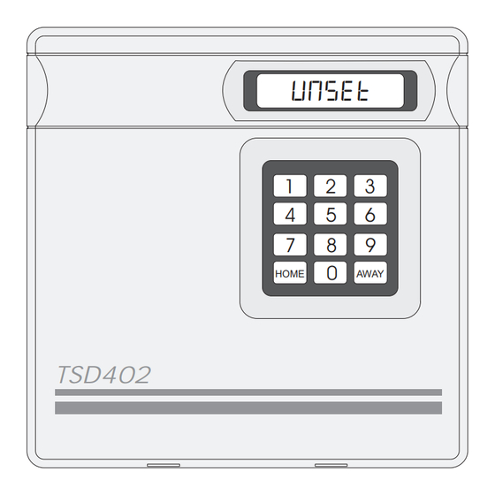
TSD402 Intruder Alarm Control Panel & Speech Dialler UNSET HOME AWAY TSD402 Installation & Programming Instructions... -
Page 2: Table Of Contents
Contents Regulatory Requirements ........1 General, Application &... -
Page 3: Regulatory Requirements
Direct exchange lines (PSTN) supporting DTMF (Tone dialling) or Loop Disconnect (Pulse Dialling). • PABX exchanges (with or without secondary proceed indication). The TSD402 is not suitable for connection as an extension to a pay phone or 1+1 carrier systems. Approval The TSD402 is approved for the following usage: •... -
Page 4: Connections & Compatibility With Pabxs
The authorised maintainer A professional installer after 14 days written notice to the authorised maintainer. Ringer Equivalence Number (REN) The Ringer Equivalence Number for the TSD402 is 0.0 and as such any number can be simultaneously connected to an exclusive line. -
Page 5: Overview
Overview Introduction The TSD402 is a 5 zone (+ Final Exit) control panel with an integral Speech Dialler. It is ideally suited for domestic and small commercial installations, which require additional security through the communication of audio alarm messages over the telephone line. -
Page 6: Speech Dialler Operation
Overview TSD402 Installation Manual The TSD402 incorporates a 3 button set facility which simplifies the setting and part-setting of the system for user. When the user wishes to full set the system, they simply enter the first 2 digits of their passcode followed by the AWAY key. To part-set the system, they simply enter the first 2 digits of their passcode followed by the HOME key. -
Page 7: Tone Dialling Simulators (Tone Pads) & Specifications
Tone Dialling simulators (Tone Pads) For the acknowledgement procedure to work successfully the TSD402 "looks" for a 1 second of tone between 600Hz and 1400Hz. This is supplied most reliably by the [8] button used for MF dialling although other buttons may work if pressed accidentally. -
Page 8: System Planning
System Planning General The TSD402 is a flexible system, but care must be taken in planning the installation to provide maximum protection with minimum installation effort. Survey the household and determine where each security device is to be fitted. Wherever possible, try to conceal wiring (e.g., in the loft, under carpets or floorboards and inside... -
Page 9: External Sounder & Detection Devices
TSD402 Installation Manual System Planning External Sounder The External Sounder should be mounted as high as possible so that it is visible and out of reach to potential intruders. A six core cable is required for connection to the sounder, it should enter directly through the wall and into the sounder via the cable entries in the back plate. -
Page 10: Final Exit, Keyswitch & Power Supply Considerations
System Planning TSD402 Installation Manual Final Exit This is the point at which the user leaves and enters the premises (normally the front door). When setting the system the user must leave the premises via the exit route and through the Final Exit zone. -
Page 11: System Installation
Figure 1 TSD402 Control Panel layout Installing the Control Panel For your safety, installation of the TSD402 must be conducted in the following sequence. Remove the screw from the top of the control panel and lift away the front cover. -
Page 12: Mains Connection
A 2.1Ah battery must be fitted to the control panel to allow the system to function during a mains fail condition. The TSD402 is equipped with a "Battery Protection" circuit so that if a battery is accidentally reverse connected or its voltage is below 8V, the "Battery Fault" LED illuminates. To clear... -
Page 13: Control Panel Pcb Layout
T ransformer Telephone Line Connection Terminals A.C. (T.N.V Circuit) Figure 2 TSD402 PCB Layout Connections & Controls The main PCB has the following "Jumper Plugs" (JP), indicator LEDS and terminal connections: TRIG POLARITY (JP1) This jumper-link sets the signal polarity for the auxiliary speech dialler trigger inputs. - Page 14 System Installation TSD402 Installation Manual Connections & Controls (Cont.) EXT. VOLUME (VR1) If an extension loudspeaker is connected to the control panel, the volume of keypad bleeps, chime, entry and exit tones may be adjusted using this control (clockwise to increase). Alarm tones are always full volume.
- Page 15 TSD402 Installation Manual System Installation ZONE 5 (PA) This pair of terminals may be connected to any type of normally closed detection device. When activated during a set condition, a full alarm is generated. It is also possible to program the zone as "PA"...
- Page 16 System Installation TSD402 Installation Manual Connections & Controls (Cont.) TRG - This terminal provides the switched negative bell trigger output (max. 500mA). It should be connected to the -ve bell trigger input on the external sounder or SAB module. The output may be programmed for SAB or SCB operation: When programmed as SAB, the output will switch to 0V on alarm.
-
Page 17: Connection Diagram
TSD402 Installation Manual System Installation Connection Diagram External Sounder TSD402 TRIGGER - ALM - STROBE - RST - HOLD OFF + TRG - HOLD OFF - STB- TAMPER RETURN - TMP - TAMPER ALARM To Zone 1 Terminal Strip (Not supplied) -
Page 18: Installing A Ts400 Remote Keypad
TSD402 Installation Manual Installing a TS400 Remote keypad Up to four TS400 remote keypads may be connected to the TSD402 control panel. The remote keypad is supplied with an interface PCB which plugs onto the main PCB. Remote keypad(s) may be sited up to a maximum of 50 metres from the control panel using a six-core cable for connections. -
Page 19: Telephone Line Connections
Figure 4 Signalling Types for Auxiliary Dialler Inputs Telephone Line Connections There are two methods of connection for the TSD402 to the telephone line. The first is to use the 2 metre lead supplied (recommended method of connection) which will directly plug into any standard British Telecom telephone socket. -
Page 20: Pre Power-Up Checks & Initial Power-Up
System Installation TSD402 Installation Manual Pre Power-Up Checks Before applying any power to the system, give the system one final check to ensure that: The telephone lead is unplugged from the telephone socket. The wiring and connections conforms to the requirements detailed in this manual. - Page 21 TSD402 Installation Manual System Installation Initial Power-Up (Cont.) Switch on the 240V mains supply and remove the screwdriver blade. The internal alarm will bleep every 30 seconds the display will show: CF- Connect the standby battery. If the display shows: BATT. FLT and the internal alarm sounds, then the battery may have been incorrectly connected or its voltage is below 8V.
-
Page 22: Programming
Programming TSD402 Installation Manual Programming Programming Menus There are two programming menus within the system. The engineer's programming menu and the user programming menu. The figure below shows the structure of both programming menus, however the engineers programming menu is only covered in full detail within this manual. -
Page 23: Program Zones
TSD402 Installation Manual Programming Program Zones (key The TSD402 zones may be programmed so that they perform different functions. The zones types are as follows: Night (N) Zones 1-5 may be programmed as a Night zone, this type of zone will only generate a full alarm when activated during a set condition. -
Page 24: View Event Log
Zone 3 = Keyswitch Zone 4 = Fire View Event Log (key The TSD402 will store up to 64 events within the memory log. When this option is selected the most recent event is displayed first. Pressing the key takes you backwards through the Log and pressing the key abandons the View Log option. -
Page 25: Walk Test
TSD402 Installation Manual Programming View Event Log (Cont.) Ensure that the "ENGR. OPTION -" is displayed. Press to select the View Log option. Press the key to move backwards through the Log. When completed, press to abandon the View Log option. -
Page 26: Entry Time
Programming TSD402 Installation Manual Entry Time (key When the entry procedure is initiated, the Entry Timer is started and the display counts down the remaining time. If a valid user passcode is not entered when the timer reaches zero, a full alarm tone is generated from the internal sounders only and the timer is restarted. If a valid user passcode is not entered when the timer reaches zero for the second time the external sounder is activated. -
Page 27: System Options
000 (disable Remote Reset) , enter "000" When completed, press to accept, a two tone acceptance tone will be heard. System Options (key The TSD402 has six system options which change the functionality of the system. The options are as follows: Bell Output Type SAB (A) When programmed as SAB the output will switch to 0V on alarm. - Page 28 Programming TSD402 Installation Manual Re-arm Options 1 re-arms (1) When an alarm occurs, the internal and external sounders are operated for the length of the bell duration. At the end of this time the alarm is silenced and the all zones are re-armed. Any zones that are active will be automatically isolated until they return to their healthy state.
-
Page 29: Speech Dialler Alarm Options
TSD402 Installation Manual Programming System Options (Cont.) Ensure that the "ENGR. OPTION -" is displayed. Press to select System Options. Press keys 1 to 7 to toggle between the two settings for each option (as Shown Below). When completed, press to accept, a two tone acceptance tone will be heard. -
Page 30: Returning To The Unset Mode
Programming TSD402 Installation Manual Returning to the Unset Mode (key Once all the engineer programming is completed the system can be returned to the unset mode by pressing the key. However since the speech dialler has not yet been programmed the display will still show the "PLEASE RE-RECORD" message. This will be cleared when one or more of the speech dialler messages have been recorded (see User Manual for full details). -
Page 31: Installation Record
TSD402 Installation Manual Installation Record Installation Record Zone Type Location Chime Home On / Off Armed / Omitted Night / Access Night / Access On / Off Armed / Omitted Night / keyswitch On / Off Armed / Omitted On / Off... - Page 32 Engineer's Quick Reference Guide Function Action Options 1 Zone 1 Program Zones Press 1-6 to toggle = Night or Access 2 Zone 2 zone types = Night or Access 3 Zone 3 Press to end = Night or KeySwitch 4 Zone 4 = Night or Fire 5 Zone 5 = Night or PA...
Need help?
Do you have a question about the TSD402 and is the answer not in the manual?
Questions and answers