
Related Manuals for Menvier Security TS510


Summary of Contents for Menvier Security TS510
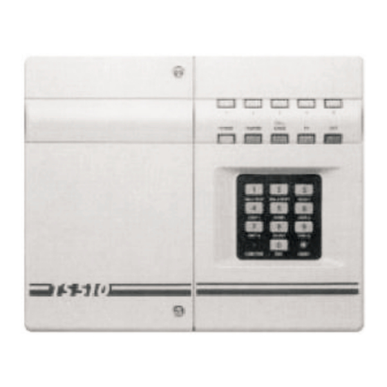
- Page 1 TS510 & TS500 Installation & User Guide Compatible Equipment TS510 REM - Remote Keypad 9040 - Loudspeaker DC54/58 - Digital Communicator SD1+ - Speech Dialler 1 of 10 496525 Issue A TS510 and TS500...
-
Page 2: Specification
This installation manual is intended to help you install 5 Programmable Zones with individual Tamper circuits, the TS510 as quickly and easily as possible. It is plus fixed PA and Exit Terminator Outputs for Bell, therefore very important to read the manual Strobe and 16 Ohm Loudspeaker thoroughly before starting any work. -
Page 3: System Wiring
TS510 & TS500 System Wiring All ZONE and TAMPER inputs are linked out prior to Ensure that the circuit, tamper and remote keypad despatch from the factory. Remove these links from cables are not routed adjacent to AC or RF cabling... -
Page 4: Remote Keypad
TS510 & TS500 Remote Keypad Digital Communicator Up to 4 remote keypads (order code: TS510 REM), can The DC3 is an 8 channel plug-on digital communicator be fitted, these are supplied with an interface which specifically designed to operate with Menvier Security plugs onto the main panel PCB. - Page 5 Fig 6 TS500/510.IF and TS500.REM Connections Fig4 TS510.IF and TS510.REM Connection Fit the TS510.IF to the panel plug taking care to ensure Remove the shorting link (if fitted) from the top 2 pins that correct alignment is made and that no pins are of the DIGI INTERFACE connector.
-
Page 6: Key Functions
TS510 & TS500 Defaults ENGINEER CODE = 1234 OPTIONS 1: (NOT APPLICABLE TO TS500) MASTER USER CODE = 5678 Bell output is SAB LAST EXIT ZONE = ZONE 1 Alarm cleared on reset ACCESS ZONE = ZONE 2 Audible P.A. - Page 7 TS510 & TS500 Engineers Programming ENTRY TIME: Press [5] and 3 zone LED’s will light, indicating that a 3 digit entry time (in secs) is required, ENTER ENGINEER CODE AND THE [CALL ENGR] LED WILL Once complete the confirmation tone will be heard ILLUMINATE TOGETHER WITH THAT OF THE ZONE WHICH e.g.
-
Page 8: Engineer Code
TS510 & TS500 OUTPUT 1: ENGINEER CODE: Press [6] [5] and one of the following Press [7] and 4 zone LEDs will light indicating LEDs will light, showing which function that a 4 digit engineer code is required. is indicated by Output 1:... -
Page 9: User Functions
TS510 & TS500 User Functions Activate selected detectors or door contacts and smoke detectors if fitted. Zone light illuminates and two tone sounder is SETTING THE SYSTEM heard for each device activated. Enter your passcode - the (UNSET) light will Press [0] (END) to complete test - [UNSET] will flash. -
Page 10: Fault Finding
TS510 & TS500 (FLASHING=OMITTED, UNLIT=NORMAL) When satisfied press [0] (END). Two tone confirmation sound heard - [UNSET] will illuminate. Fault finding [CALL ENGR] flashing Indicates there is a telephone line problem if you are connected to a monitoring station. Check telephone and call engineer.
Need help?
Do you have a question about the TS510 and is the answer not in the manual?
Questions and answers