
Related Manuals for Beckman Coulter Microfuge 16


Summary of Contents for Beckman Coulter Microfuge 16
- Page 1 Instructions For Use Microfuge 16 Centrifuge FX241.5P and FX121.5P Rotors PN A49436AG February 2014 Beckman Coulter, Inc. 250 S. Kraemer Blvd. Brea, CA 92821 U.S.A.
- Page 2 Trademarks Beckman Coulter, the stylized logo, Microfuge, and Beckman Solution 555 are trademarks of Beckman Coulter, Inc. and are registered in the USPTO. All other trademarks, service marks, products, or services are trademarks or registered trademarks of their respective holders.
-
Page 3: Safety
Safety Read all product manuals and consult with Beckman Coulter-trained personnel before attempting to operate instrument. Do not attempt to perform any procedure before carefully reading all instructions. Always follow product labeling and manufacturer’s recommendations. If in doubt as to how to proceed in any situation, contact your Beckman Coulter Representative. -
Page 4: Electrical Safety
Safety Centrifuge Safety Notice Electrical Safety To reduce the risk of electrical shock, this equipment uses a three-wire electrical cord and plug to connect the centrifuge to earth-ground. To preserve this safety feature: • Make sure that the matching wall outlet receptacle is properly wired and earth-grounded. Check that the line voltage agrees with the voltage listed on the name-rating plate affixed to the centrifuge. -
Page 5: Rotor Safety Notice
Beckman Coulter centrifuge/rotor system. Rotor safety or reliability cannot be assured if used in a centrifuge not of Beckman Coulter’s manufacture or in a Beckman Coulter centrifuge that has been modified without Beckman Coulter’s approval. -
Page 6: Rohs Notice
Safety RoHS Notice • If disassembly reveals evidence of leakage, you should assume that some fluid escaped the rotor. Apply appropriate decontamination procedures to the centrifuge and accessories. • Never exceed the maximum rated speed of the rotor and labware in use. Refer to the section on RUN SPEEDS, and derate the run speed as appropriate. -
Page 7: Table Of Contents
Contents Safety, iii Centrifuge Safety Notice, iii Alerts for Danger, Warning, Caution, Important, and Note, iii Safety During Installation and/or Maintenance, iii Electrical Safety, iv Safety Against Risk of Fire, iv Mechanical Safety, iv Chemical and Biological Safety, iv Rotor Safety Notice, v RoHS Notice, vi... - Page 8 Contents Controls and Indicators, 2-4 Power Switch, 2-4 Control Panel, 2-4 Display, 2-5 Speed, 2-6 Time, 2-7 Rotor Function and Specifications, 2-8 FX241.5P Rotor Specifications, 2-9 FX121.5P Rotor Specifications, 2-10 Tubes and Adapters, 2-11 Temperature Limits, 2-11 Speeds, 2-12 CHAPTER 3: Operation, 3-1 Introduction, 3-1 Procedure, 3-1...
- Page 9 Returning a Centrifuge or Rotor, 5-5 Supply List, 5-6 Replacement Parts, 5-6 Supplies, 5-6 APPENDIX A: Installation, A-1 Installing the Centrifuge, A-1 Electrical Requirements, A-2 Test Run, A-3 Beckman Coulter, Inc., Microfuge 16 Centrifuge Warranty Beckman Coulter, Inc., Benchtop Rotor Warranty Related Documents...
- Page 10 Illustrations Illustrations The Microfuge 16 Centrifuge, 2-1 The Control Panel, 2-4 Installing the Rotor and Tightening the Tie-Down Screw, 3-3 Dimensions of the Microfuge 16 Centrifuge, A-2...
- Page 11 Tables Tables Available Tubes and Adapters for the FX241.5P and FX121.5P Rotors, 2-11 RCF Values at Various Speeds for the FX121.5P Rotor, 3-7 Troubleshooting Chart, 4-1 Error Message Chart., 4-2...
- Page 12 Tables...
-
Page 13: Introduction
Declarations of conformity and certificates of compliance are available at www.beckmancoulter.com. Scope of Manual This manual is designed to familiarize you with the Beckman Coulter Microfuge 16 centrifuge, its functions, specifications, operation, and routine operator care and maintenance. We recommend that you read this entire manual, especially... -
Page 14: Conventions
For Beckman Coulter products bearing this label please contact your dealer or local Beckman Coulter office for details on the take back program that will facilitate the proper collection, treatment, recovery, recycling and safe disposal of the device. -
Page 15: Description
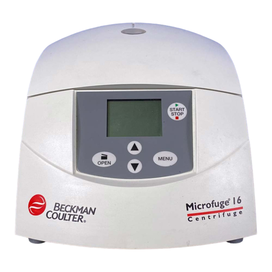
2.1) is a microprocessor-controlled compact benchtop centrifuge that generates centrifugal forces required for a wide variety of applications. Together with the Beckman Coulter FX241.5P and FX121.5P rotors, designed specifically for use in this centrifuge, applications include: • Nucleic acid plasmids and bacteriophages isolation. -
Page 16: Specifications
Safety Features The Microfuge 16 centrifuge has been designed and tested to operate safely indoors at altitudes up to 2000 m (6562 ft). An electromechanical door-locking mechanism prevents operator contact with spinning rotors. When the door is closed it locks automatically. The door can be unlocked and opened only when the power is on and the rotor is at rest. -
Page 17: Ground Wire Check
The name rating plate is affixed to the rear of the centrifuge. Check that the line voltage agrees with the voltage listed on this name rating plate before connecting the centrifuge. Always mention the serial number and the model number shown when corresponding with Beckman Coulter regarding your centrifuge. -
Page 18: Controls And Indicators
Description Controls and Indicators Controls and Indicators Power Switch A two-position rocker switch ( , on; , off), located on the back of the centrifuge next to the power cord outlet, controls electrical power to the centrifuge. Control Panel The control panel (Figure 2.2), including touch keys and hermetically sealed LCD display, is mounted at an angle on the centrifuge front for easy visibility and access. -
Page 19: Display
Description Display Up and Down Arrow Pressing the up or down arrow key adjusts parameter settings as follows: Keys • Speed and time settings can be adjusted upwards or downwards. • After the MENU key is pressed four times, pressing the up arrow key displays slow acceleration and deceleration settings. -
Page 20: Speed
Description Display • The middle line displays the optional settings (slow acceleration and deceleration), soft (slow deceleration), or (standard acceleration and deceleration) if selected. If the soft stop stop setting is selected, will flash for 20 seconds and then no longer be displayed. stop stop During operation:... -
Page 21: Time
Description Display Time Timed and continuous runs can be selected by pressing the key until flash in the MENU display, and then pressing the up and down arrow keys to adjust the setting. • A timed run can be set from 10 seconds up to 99 minutes 59 seconds in 1-second increments. The up and down arrows are used to adjust the setting. -
Page 22: Rotor Function And Specifications
Rotor Function and Specifications FX241.5P Rotor Two rotors are available for use in the Microfuge 16 centrifuge. The FX241.5P rotor, rated for 14,800 rpm, is a fixed angle rotor with two concentric rows of twelve tube cavities. The tube angle for the outer row is 32 degrees, and the tube angle for the inner row is 53 degrees. -
Page 23: Fx241.5P Rotor Specifications
Description Rotor Function and Specifications FX241.5P Rotor Specifications Outer Row Dimensions (66 mm) 32° (outer row) (38 mm) 53° (inner row) (30 mm) (66 mm) Axis of Rotation Inner Row Dimensions Specification Description Maximum speed 14,800 rpm Density rating at maximum speed 1.2 g/mL 600 to 900 rpm Critical speed range... -
Page 24: Fx121.5P Rotor Specifications
Description Rotor Function and Specifications FX121.5P Rotor Specifications 45° r min (29 mm) (62 mm) Axis of Rotation Specification Description Maximum speed 14,800 rpm Density rating at maximum speed 1.2 g/mL 600 to 900 rpm Critical speed range 15 183 × g Relative Centrifugal Field at maximum speed at r (62 mm) -
Page 25: Tubes And Adapters
Description Tubes and Adapters Tubes and Adapters Available tubes and adapters for the FX241.5P and FX121.5P rotors are listed in Table 2.1. Be sure to observe the maximum speeds shown. If using commercially available tubes, follow the manufacturer’s recommended speed and fill guidelines. Refer to Chemical Resistances, publication IN-175, for information on the chemical compatibilities of labware materials. -
Page 26: Run Speeds
Description Run Speeds Run Speeds The centrifugal force at a given radius in a rotor is a function of speed. Comparisons of forces between different rotors are made by comparing the rotors’ relative centrifugal fields (RCF). When rotational speed is adjusted so that identical samples are subjected to the same RCF in two different rotors, the samples are subjected to the same force. -
Page 27: Chapter 3: Operation
CAUTION The Microfuge 16 centrifuge and FX241.5P and FX121.5P rotors were developed, manufactured, and tested for safety and reliability as part of a Beckman Coulter centrifuge/rotor system. Safety or reliability of the centrifuge cannot be assured if used with any other rotor. -
Page 28: Preparation And Loading
Although rotor components and accessories made by other manufacturers may fit in the FX241.5P and FX121.5P rotors, their safety in these rotors cannot be ascertained by Beckman Coulter. Use of other manufacturers’ components or accessories in the FX241.5P and FX121.5P rotors may void the rotor warranty and should be prohibited by your laboratory safety officer. - Page 29 Operation Preparation and Loading Press the power switch to on ( • Power is applied to the centrifuge. — The centrifuge display is illuminated. — The door latch releases. The power switch is on the centrifuge rear panel. Ensure that the rotor tie-down screw (A46544) is in good condition and the threads are free of foreign matter.
- Page 30 Operation Preparation and Loading Secure the rotor to the drive shaft with the rotor tie-down screw (see Figure 3.1). a. Tighten the screw by turning it to the right (clockwise) by hand. b. Once the screw contacts the rotor body, continue turning until a stop is felt. •...
-
Page 31: Starting A Timed Or Continuous Run
Operation Starting a Timed or Continuous Run Starting a Timed or Continuous Run Press the key until flashes in the display. MENU • The speed setting can be adjusted Press the up and/or down arrow keys to select a run speed, in rpm or rcf. •... - Page 32 Operation Starting a Timed or Continuous Run Press the key four times. MENU • If previously selected, will flash. soft soft stop — Slow (soft) acceleration and deceleration settings can be selected. Press the up arrow key repeatedly to display (slow acceleration and deceleration), soft soft stop...
-
Page 33: Rcf Display
Operation Starting a Short (Pulse) Run When the rotor reaches 0 rpm, the door latch releases automatically. • Lift the door to full open position and unload the rotor. NOTE Depending upon the duration of the event, transient power-line interruptions may cause this equipment to decelerate or reset with the possible loss of in-process operation. -
Page 34: Removal And Sample Recovery
Operation Removal and Sample Recovery Release the key to begin deceleration. START STOP CAUTION Do not lift or move the centrifuge while the rotor is spinning. When the rotor reaches 0 rpm, the door latch releases automatically. • Elapsed time is displayed for several seconds after the rotor reaches 0 rpm. Lift the door to full open position and unload the rotor. -
Page 35: Chapter 4: Troubleshooting
Perform the recommended corrective action in sequence, as listed. If you are unable to correct the problem, call your Beckman Coulter representative. To help diagnose and correct the problem, try to gather as much information about the situation as you can: •... -
Page 36: Error Messages
Confirm the error message by pressing the OPEN key. a. If the recommended action does not correct the problem, call Beckman Coulter Field Service. Accessing the Rotor in Case of Power Failure If the facility power fails you will have to restart the run when the power is restored. In the event of an extended power failure, it may be necessary to trip the door-locking mechanism manually to remove the rotor and retrieve your sample. - Page 37 Troubleshooting Accessing the Rotor in Case of Power Failure WARNING The following procedure may expose the operator to the possibility of contact with a spinning rotor. Turn the power off ( ) and disconnect the centrifuge from the main power source before proceeding. Never attempt to override the door interlock system while the rotor is spinning.
- Page 38 Troubleshooting Accessing the Rotor in Case of Power Failure Remove the tool, return the instrument to its normal position and remove the rotor. WARNING Never try to slow or stop the rotor by hand. Open the door and remove the rotor. PN A49436AG...
-
Page 39: Chapter 5: Care And Maintenance
CHAPTER 5 Care and Maintenance Introduction For maintenance not covered in this manual, contact Beckman Coulter Field Service (1-800-742-2345 in the U.S.A.; customers outside the United States should contact their local Beckman Coulter representative). NOTE It is your responsibility to decontaminate the centrifuge, rotors, and accessories before requesting service by Beckman Coulter representatives. -
Page 40: Rotor Preventive Maintenance
Periodically (at least monthly) inspect the rotor, especially inside cavities, for damage. a. If damage is evident, do not run the rotor. Contact your Beckman Coulter representative for information about the Field Rotor Inspection Program and the rotor repair center. -
Page 41: Centrifuge Cleaning
Care and Maintenance Cleaning Centrifuge Cleaning To prevent accumulations of sample and/or dust, keep the interior of the rotor chamber clean and dry by frequent wiping with a cloth or paper towel. Clean the drive shaft, shaft cavity, threads, and the tie-down screw at least once a week using a mild detergent such as Beckman Solution 555 (339555) and a soft brush. -
Page 42: Decontamination
See Chemical Resistances for more information regarding chemical resistance of centrifuge and accessory materials. While Beckman Coulter has tested these methods and found that they do not damage the centrifuge, no guarantee of sterility or disinfection is expressed or implied. When sterilization or disinfection is a concern, consult your laboratory safety officer regarding proper methods to use. -
Page 43: Storage And Transportation
Use the minimum immersion time for each solution, per laboratory standards. While Beckman Coulter has tested these methods and found that they do not damage the rotor or components, no guarantee of sterility or disinfection is expressed or implied. When sterilization or disinfection is a concern, consult your laboratory safety officer regarding proper methods to use. -
Page 44: Supply List
Beckman Coulter office, or visit www.beckmancoulter.com. Contact Beckman Coulter Sales (1-800-742-2345 in the United States) for information about ordering parts and supplies. See the Beckman Coulter Benchtop Rotors, Tubes & Accessories catalog (BR-9742, available at www.beckmancoulter.com) for detailed information on ordering rotors, tubes, and accessories. -
Page 45: Appendix A: Installation
APPENDIX A Installation Installing the Centrifuge WARNING Do not place the centrifuge near areas containing flammable reagents or combustible fluids. Vapors from these materials could enter the centrifuge’s air system and be ignited by the motor. No hazardous materials should be handled or stored within the 30-cm (1-ft) boundary surrounding the centrifuge. -
Page 46: Electrical Requirements
Installation Electrical Requirements Figure A.1 Dimensions of the Microfuge 16 Centrifuge 39.5 15.6 17.6 26.6 10.5 22.6 Electrical Requirements 100 to 120-V centrifuge: 100–120 VAC, 4 A, 50/60 Hz 220 to 240-V centrifuge: 220–240 VAC, 2 A, 50/60 Hz Power cord: 2.5-m (8-ft) power cord with grounded plug is supplied with the centrifuge... -
Page 47: Test Run
Installation Test Run To ensure safety the centrifuge should be wired to a remote emergency switch (preferably outside the room where the centrifuge is housed, or adjacent to the exit from that room), in order to disconnect the centrifuge from the main power source in case of a malfunction. Test Run We recommend that you make a test run to ensure that the centrifuge is in proper operating condition following shipment. - Page 48 Installation Test Run PN A49436AG...
-
Page 49: Beckman Coulter, Inc., Microfuge 16 Centrifuge Warranty
Beckman Coulter is minor, or unless such modification is merely the installation of a new Beckman Coulter plug-in component for such product(s). - Page 50 Beckman Coulter, Inc., Microfuge 16 Centrifuge Warranty Warranty-2 PN A49436AG...
-
Page 51: Beckman Coulter, Inc., Benchtop Rotor Warranty
Subject to the conditions specified below and the warranty clause of the Beckman Coulter, Inc., terms and conditions in effect at the time of sale, Beckman Coulter agrees to correct either by repair or, at its election, by replacement, any defects of material or workmanship which develop within seven (7) years after delivery... - Page 52 Beckman Coulter, Inc., Benchtop Rotor Warranty Warranty-4 PN A49436AG...
- Page 53 English / Deutsch / Español / Français / Italiano / Portugués / Русский / 中文 / 日本語 / 한국어 Symbol Simbole Symbol символ Simbolo 符号 Title / Titel / Titulo / Titre / Titolo / Titulo / Название / 标题 / タイトル / 제목 Symbole 記号...
-
Page 54: Related Documents
Use and Care of Centrifuge Tubes and Bottles PN IN-192 Available in hard copy or electronic pdf by request. Benchtop Rotors, Tubes, and Accessories catalog PN BR-200634 Available at www.beckmancoulter.com www.beckmancoulter.com © 2014 Beckman Coulter, Inc. All Rights Reserved...
Need help?
Do you have a question about the Microfuge 16 and is the answer not in the manual?
Questions and answers