Table of Contents
Advertisement
Quick Links
Installation/Owner's Manual
Use this manual for circuit board 4100-010 Revision AA or higher.
EXTERNAL ENTRAPMENT PROTECTION MUST be
installed or the gate operator WILL NOT function.
Solar Powered
Date Installed:
Installer/Company Name:
Phone Number:
Leave Manual with Owner
UL 325 Compliant
Model 6524-081
Model 6524-081
Model 6524-081
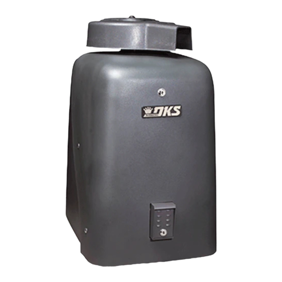
Solar Powered Vehicular Swing Gate Operator
Circuit Board
Serial Number
and Revision Letter:
Copyright 2016 DoorKing, Inc. All rights reserved.
Solar Powered
Copyright 2009 DoorKing, Inc. All rights reserved.
6524-066-G-7-16
Advertisement
Table of Contents
Troubleshooting

Related Manuals for DKS 6524-081


Summary of Contents for DKS 6524-081
- Page 1 Installation/Owner’s Manual Model 6524-081 Model 6524-081 Model 6524-081 Solar Powered Vehicular Swing Gate Operator Use this manual for circuit board 4100-010 Revision AA or higher. 6524-066-G-7-16 EXTERNAL ENTRAPMENT PROTECTION MUST be installed or the gate operator WILL NOT function. Solar Powered...
-
Page 2: Quick Guide: Dip-Switches
QUICK GUIDE: DIP-Switches See page 19 for more information about DIP-switches. Reset button on circuit board MUST be pressed before new DIP-switch settings will take affect. SW 1 (Top 8 Switches) Switch Function Setting Description Changes direction Operator operator will cycle open Opens Opens Opening... -
Page 3: Quick Guide: Terminal Descriptions
QUICK GUIDE: Terminal Descriptions See page 27 for terminal wiring. Terminals 1, 2 and 3 are ALWAYS powered up, even after circuit board has powered down to manage the power drain on the batteries, see page 16. UL 325 Opening devices MUST connect to terminal 2. See pages 22 and 23 SW 1 This input ONLY functions when gate is... - Page 4 DKS Solar Power Kit: Solar Panel Power - Continuous Batteries One 24 VDC Solar Panel DKS Solar Power Kit: ONLY Battery Power - 150 + Cycles P/N 2000-070 Unkown when using Third Party Solar Power Setup Battery Power Note: The number of gate cycles when using ONLY battery power WILL vary depending on gate weight, gate length, operating condition of gate hardware, temperature and amount of charge in batteries.
-
Page 5: Table Of Contents
6.1 DC Power Switch and Alarm Reset Button 6.2 Shutdown Conditions 29-30 6.3 Manual Gate Operation 30-31 SECTION 7 - MAINTENANCE AND TROUBLESHOOTING 7.1 Maintenance 7.3 Troubleshooting 33-34 7.2 Built-In Diagnostics 7.4 Accessory Items 7.5 Gearbox Shaft Extension Replacement Model 6524-081 Solar Input Power Wiring Diagram 6524-066-G-7-16... -
Page 6: Swing Gate Requirements
Swing Gate Requirements The operator is intended for installation only on gates used for vehicles. Pedestrians must be supplied with a separate access opening. The pedestrian access opening shall be designed to promote pedestrian usage. Locate the gate such that persons will not come in contact with the vehicular gate during the entire path of travel of the vehicular gate. -
Page 7: Safety Information For Swing Gate Operators
Safety Information for Swing Gate Operators Standard Non-contact Sensor Minimizes the potential of the gate closing on vehicular or other traffic Reverse Loop that loops cannot sense. Minimizes the potential of the gate closing when a vehicle is present. Warning Signs Number and placement of loops is Permanently mounted dependent on the application. -
Page 8: Astm 2200 Standard For Gate Construction
ASTM F2200 Standard for Gate Construction Vehicular gates should be constructed and installed in accordance with ASTM F2200; Standard Specification for Automated Vehicular Gate Construction. For a copy of this standard, contact ASTM directly at 610-832-9585; service@astm.org; or www.astm.org. Important Safety Instructions WARNING - To reduce the risk of injury or death: 1. -
Page 9: Important Notices
• For gate operators utilizing contact sensors: 1. One or more contact sensors shall be located where the risk of entrapment or obstruction exist, such as at the leading edge, trailing edge, and post mounted both inside and outside of a vehicular horizontal slide gate. 2. -
Page 10: Ul325 Entrapment Protection
UL 325 Entrapment Protection UL 325 Classifications Authoriz ed Personn el ONLY Class I - Residential Class III - Industrial/Limited Access Vehicular Gate Operator Vehicular Gate Operator A vehicular gate operator (or system) intended for use in garages A vehicular gate operator (or system) intended for use in an or parking areas associated with a residence of one-to four single industrial location or building such as a factory or loading dock families. -
Page 11: Glossary
Glossary GATE - A moving barrier such as a swinging, sliding, raising, lowering, or the like, barrier, that is a stand-alone passage barrier or is that portion of a wall or fence system that controls entrance and/or egress by persons or vehicles and completes the perimeter of a defined area. -
Page 12: Section 1 - Installation
SECTION 1 - INSTALLATION Prior to beginning the installation of the swing gate operator, we suggest that you become familiar with the instructions, illustrations, and wiring guide-lines in this manual. This will help insure that your installation is performed in an efficient and professional manner compliant with UL 325 safety and ASTM F2200 construction standards. -
Page 13: Type Of Installations
1.3 Type of Installations Standard Installation Recommended for all gate lengths opening 90°. 46” 14” 90° 23” 38.5” 35” 3” 29.5” 28” 22” Gate opens in approximately 15 seconds. Concrete Pad 90° 46” Concrete Pad Location Operator Installation Alternate Installation Recommended for gates up to 14 feet opening 90°. - Page 14 Compact Installation Recommended for gates NO LARGER THAN 10 FEET opening 90°. 34” 13” 16.5” 90° 26.5” 29.5” 2” 26.5” 28” 22” Concrete Pad 23” Concrete Pad Location Operator Installation Gates Opening Wider than 90° Installation 90° Plus Installation requires the Standard Compact Installation’s concrete pad to be moved 2” away from the gate’s open position.
-
Page 15: Securing Operator To Pad
1.4 Securing Operator to Pad Permanently attach the operator to the concrete pad using four (4) 3/8” x 3” sleeve anchors (not supplied). Sleeve Anchor (Not supplied) 1.5 Attach Gate Bracket Release hub with release tool. DO NOT REMOVE HUB! Bolt crank arm to operator. -
Page 16: Determining Arm Lengths
1.6 Determining Arm Lengths Slide elbow assembly back and fourth, manually opening and closing gate until satisfied with the gate’s 90° open and fully closed positions. Mark and cut off excess arms. Secure arms to elbow assembly with 6 allen screws. Tighten hub and replace release tool. Install safety covers. -
Page 17: Concerns Before Solar Panel Installation
OPTIONAL DKS Solar Power Kit P/N 2000-070. If other solar sources are used, output MUST be 24 VDC. 6524-066-G-7-16... -
Page 18: Solar Panel Positioning
1.9 Solar Panel Positioning These charts should be used only for estimates. Solar systems can vary from this information. These maps do not take into account small climate changes and may not be 100% accurate for all locations. Solar Panel MUST Point “TRUE SOUTH” It is important for proper system operation that the solar panel is oriented to TRUE SOUTH. -
Page 19: Section 2 - Solar Power To Operator
K ! ! MATTERS! DO NOT connect an AC input power wire t t e t h e Wire to the Model 6524-081’s power terminal l e a a t i DKS Solar Power Kit 1 8 A t o g... -
Page 20: Setting Input Power Jumper And Turning Power On
2.2 Power Select Jumper and Turning Power ON The “POWER SEL” jumper on the circuit board MUST be set correctly or operator will not function correctly. DO NOT cycle the operator until the “DIP-Switches” and the “Limit Switches” have been adjusted. Damage could occur to the gate and gate operator. See pages 18-20. -
Page 21: Section 3 - Adjustments
SECTION 3 - ADJUSTMENTS The switch settings and adjustments in this chapter should be made after your installation and wiring to the operator(s) is complete. Whenever any of the programming DIP-switches on the circuit board are changed, DC power switch must be shut-off, and then turned back on OR press reset button for the new setting to take effect. -
Page 22: Dip-Switch Settings For 4100 Circuit Board
3.2 DIP-Switch Settings for 4100 Circuit Board The two DIP-switches located on the circuit board are used to program the operator to operate in various modes and to turn on or off various operating features. Whenever a switch setting is changed, reset button must be pressed, located on circuit board for the new setting to take affect. - Page 23 3.2 Continued SW-1 Switch (Top 8 switches on Must OPEN the operator’s gate upon initial DC power up and Switch 1 - Operator Opening Direction: circuit board) open command. If the first open command begins to close the gate, turn DC power off and reverse this Typical Settings SW 1 switch.
-
Page 24: Limit Sensors
3.3 Limit Sensors The hub must not slip CAUTION during operation. Tighten Important Limit Sensor Adjustment Note: nut to stop any slipping. It is very important NOT to cycle the gate operator DO NOT REMOVE HUB! before the limit sensors are in the correct position or it could cause damage to the gate and operator. -
Page 25: Inherent Reverse Sensor Adjustment
3.4 Inherent Reverse Sensor Adjustment This vehicular gate operator is equipped with an inherent adjustable reversing sensor (Type A) used as entrapment protection according to UL 325 standards. The gate will reverse direction after “physically” encountering an obstruction in either the opening or closing gate cycle. -
Page 26: Section 4 - Entrapment And Safety Protection
SECTION 4 - ENTRAPMENT AND SAFETY PROTECTION External Entrapment Protection Devices: In addition to the inherent reversing sensor system, this operator has a 6-pin UL 325 terminal for the connection of photo sensors-Type B1 and/or reversing edges-Type B2 entrapment protection required by UL 325 standards. An external entrapment protection device MUST be installed or the operator will NOT function. -
Page 27: External Entrapment Protection Device Locations
4.2 Entrapment and Safety Protection Device Locations Typical UL Photo Sensor mounting height and distance away from gate. Opening-Direction Photo Sensors Closing-Direction Photo Sensors UL sensor mounted just above top of operator 5” or less Wall 21” Typical If this space is less than 16 inches, Non-Secure Side Secure Side external entrapment protection is... - Page 28 4.2 Continued Edge Transmitter OPTIONAL wireless transmitter can be used. Reversing Edge Typical Reversing Edge mounted on end of gate. Edge Transmitter OPTIONAL wireless transmitter can be used. Typical Reversing Edge mounted on bottom of gate when necessary. If the bottom of gate is greater than 6” but less than 16”...
-
Page 29: Loop Detector Wiring
4.3 Loop Detector Wiring • Loop detector wiring is shown for Diablo To help protect the operator from accidentally closing on vehicles external loop detectors. If other loop detectors are in the gate’s path, DoorKing highly recommends that loops and used, refer to the installation instructions supplied loop detectors be installed. -
Page 30: Section 5 - Wiring Terminals
SECTION 5 - WIRING TERMINALS 5.1 Terminal Descriptions Terminals 1, 2 and 3 are ALWAYS powered up, even after circuit board has powered down to manage the power drain on the batteries, see page 16. UL 325 Opening devices MUST connect to terminal 2. See pages 22 and 23 This input ONLY functions when gate is SW 1... -
Page 31: Control Wiring
5.2 Control Wiring Important: Controls intended for user activation must be located at least six 3-Wire Radio Receiver (6) feet away from any moving part of the gate and where the user is prevented from reaching over, under, around or through the gate UL 325 10-Pin Terminal to operate the controls. -
Page 32: Section 6 - Operating Instructions
SECTION 6 - OPERATING INSTRUCTIONS IMPORTANT SAFETY INSTRUCTIONS WARNING - To reduce the risk of injury or death: 1. READ AND FOLLOW ALL INSTRUCTIONS. 2. Never let children operate or play with gate controls. Keep the remote control away from children. 3. -
Page 33: Shutdown Conditions
6.2 Shutdown Conditions Under various entrapment conditions the operator will assume either a soft or hard (alarm) shutdown. To determine what type of reset action is required, you will need to understand how the different entrapment conditions affect the gate operator. -
Page 34: Manual Gate Operation
Resetting a Hard Shutdown When the operator is in a hard shutdown condition (audio alarm activated or audio alarm “chirps” every 5 seconds), to silence the alarm, press the alarm reset button. • Before resetting a hard shutdown, determine why the shutdown occurred. Inspect the gate for any obstructions along its path that could have activated the inherent entrapment sensing system. -
Page 35: Manual Release
Manual Release Unlock the cover and rotate sliding door. Never attempt to manually push open any gate with an operator attached to it until you have verified that ALL power to the operator has been shut-off. Remove release tool and place where shown. -
Page 36: Section 7 - Maintenance And Troubleshooting
SECTION 7 - MAINTENANCE AND TROUBLESHOOTING Inspection and service of this gate operator by a qualified technician should be performed anytime a malfunction is observed or suspected. High cycle usage may require more frequent service checks. 7.1 Maintenance When servicing the gate operator, always check any external reversing devices (loops, photo sensors, etc.) for proper operation. If external reversing devices cannot be made operable, do not place this operator in service until the malfunction can be identified and corrected. -
Page 37: Troubleshooting
7.2 Troubleshooting Have a good VOM meter with Min/ Max test button to check voltages and continuity. A Meg-Ohm meter capable of checking up to 500 meg-ohms of resistance is necessary to properly check the integrity of the ground loops. When a malfunction occurs, isolate the problem to one of three areas: 1) the operator, 2) the loop system, 3) the keying devices. -
Page 38: Built-In Diagnostics
Symptom Possible Solution(s) • Check the input LEDs. Any ON will hold the gate open and indicates a problem with a keying device. Gate opens but will • Check the external safety devices. Any activated will hold the gate open and indicates a problem not close. -
Page 39: Accessory Items
7.4 Accessory Items UL 325 Monitored Entrapment Protection Devices available for the model 6524 swing gate operator. Type B2 Contact Sensors (Reversing Edge) Miller Edge Sensing Edges - all models with a T2 (resistive) termination. Miller Edge Monitored Gate Link Model MGL-K20 Type B1 Non-contact Sensors (Photo Cell) Miller Edge Reflective-Guard Model RG Miller Edge Prime-Guard Model PG... -
Page 40: Gearbox Shaft Extension Replacement
7.5 Gearbox Shaft Extension Replacement Crank Arm Only P/N 6500-255 Control Arm Only P/N 2600-714 Complete Arm Kit P/N 6500-430 Crank Arm Hub Assembly Remove the TWO allen screws on bottom of hub to remove the complete hub assembly. Limit Sensors Collar P/N 6500-115 Brass Bushing 1 1/8”... -
Page 41: Model 6524-081 Solar Input Power Wiring Diagram
Model 6524-081 Solar Input Power Remote Radio Magnetic Magnetic Receiver Terminal Close Sensor Open Sensor White Gray Yellow 5 7 8 9 2 3 4 5 6 7 8 9 10 Brown SELF TEST Gray Orange Orange Yellow White REV SENSE... -
Page 42: 6524-066
Installation/Owner’s Manual Model 6524-081 Model 6524-081 Model 6524-081 Solar Powered Vehicular Swing Gate Operator Use this manual for circuit board 4100-010 Revision AA or higher. 6524-066-G-7-16 www.doorking.com DoorKing, Inc. 120 S. Glasgow Avenue Inglewood, California 90301 U.S.A. Phone: 310-645-0023 Fax: 310-641-1586...
Need help?
Do you have a question about the 6524-081 and is the answer not in the manual?
Questions and answers