Table of Contents
Advertisement
Quick Links
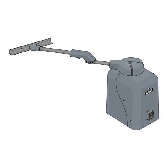
Installation/Owner's Manual
Use this manual for circuit board 4100-010 Revision AA or higher.
EXTERNAL ENTRAPMENT PROTECTION MUST be
installed or the gate operator WILL NOT function.
AC Powered
THIS PRODUCT IS TO BE INSTALLED AND SERVICED BY A TRAINED GATE SYSTEMS TECHNICIAN ONLY.
Visit www.dkslocator.com to find a professional installing and servicing dealer in your area.
Date Installed:
Installer/Company Name:
Phone Number:
Leave Manual with Owner
UL 325
Compliant
Model 6524-080
Model 6524-080
Model 6524-080
AC Powered Vehicular Swing Gate Operator
Circuit Board
Serial Number
and Revision Letter:
Copyright 2017 DoorKing, Inc. All rights reserved.
4100-010 Circuit
Board Conforms To
UL STD 991
For Solar Power, See 6524-066 Solar Manual
AC Powered
Copyright 2009 DoorKing, Inc. All rights reserved.
6524-065-R-12-17
Advertisement
Table of Contents
Troubleshooting

Related Manuals for DKS 66011200


Summary of Contents for DKS 66011200
- Page 1 Installation/Owner’s Manual Model 6524-080 Model 6524-080 Model 6524-080 AC Powered Vehicular Swing Gate Operator Use this manual for circuit board 4100-010 Revision AA or higher. 6524-065-R-12-17 For Solar Power, See 6524-066 Solar Manual EXTERNAL ENTRAPMENT PROTECTION MUST be installed or the gate operator WILL NOT function. AC Powered THIS PRODUCT IS TO BE INSTALLED AND SERVICED BY A TRAINED GATE SYSTEMS TECHNICIAN ONLY.
-
Page 2: Quick Guide: Dip-Switches
QUICK GUIDE: DIP-Switches See page 22 for more information about DIP-switches. Reset button on circuit board MUST be pressed before new DIP-switch settings will take affect. SW 1 (Top 8 Switches) Switch Function Setting Description Changes direction Operator operator will cycle open Opens Opens Opening... -
Page 3: Quick Guide: Terminal Descriptions
QUICK GUIDE: Terminal Descriptions See page 26 for terminal wiring. SW 1 • lf SW 1, switch 3 is ON, functions as a UL 325/3 Button normal full open input (Normal setting). 10-Pin Terminal • lf SW 1, switch 3 is OFF, input to 3 Button Station terminal #4 becomes the output from the UL 325... - Page 4 SPECIFICATIONS FOR MODEL 6524-080 Use this manual for the Model 6524 operator with circuit board 4100-010 Rev AA or higher ONLY. Class of Operation UL 325 Class I, II, III, IV Type of Gate Vehicular Swing Gate Only Motor Quadra Drive DC Motor Power Input: Volts@Amps 115 VAC @ 1.8 Amps OR 230 VAC @ 0.9 Amps Batteries...
-
Page 5: Table Of Contents
TABLE OF CONTENTS QUICK GUIDES Quick Guide: DIP-Switches Quick Guide - 1 Quick Guide: Terminal Descriptions Quick Guide - 2 Swing Gate Requirements Swing Gate Protection ASTM 2200 Standard for Gate Construction Important Safety Instructions Instructions regarding intended installation Important Notices UL325 Entrapment Protection Glossary SECTION 1 - INSTALLATION... -
Page 6: Swing Gate Requirements
Swing Gate Requirements The operator is intended for installation only on gates used for vehicles. Pedestrians must be supplied with a separate access opening. The pedestrian access opening shall be designed to promote pedestrian usage. Locate the gate such that persons will not come in contact with the vehicular gate during the entire path of travel of the vehicular gate. -
Page 7: Swing Gate Protection
Non-contact Sensor Swing Gate Protection Minimizes the potential of the gate closing on vehicular or other traffic that loops cannot sense. Monitored device helps Reverse Loop protect against entrapment when Minimizes the potential of the gate needed. closing when a vehicle is present. Number and placement of loops is Warning Signs dependent on the application. -
Page 8: Astm 2200 Standard For Gate Construction
ASTM F2200 Standard for Gate Construction Vehicular gates should be constructed and installed in accordance with ASTM F2200; Standard Specification for Automated Vehicular Gate Construction. For a copy of this standard, contact ASTM directly at 610-832-9585; service@astm.org; or www.astm.org. Important Safety Instructions WARNING - To reduce the risk of injury or death: 1. -
Page 9: Important Notices
Important Notices Vehicular gate operator products provide convenience and security. However, gate operators must use high levels of force to move gates and most people underestimate the power of these systems and do not realize the potential hazards associated with an incorrectly designed or installed system. These hazards may include: •... -
Page 10: Ul325 Entrapment Protection
UL 325 Entrapment Protection UL 325 Classifications Authoriz ed Personn el ONLY Class I - Residential Class III - Industrial/Limited Access Vehicular Gate Operator Vehicular Gate Operator A vehicular gate operator (or system) intended for use in garages A vehicular gate operator (or system) intended for use in an or parking areas associated with a residence of one-to four single industrial location or building such as a factory or loading dock families. -
Page 11: Glossary
Glossary GATE - A moving barrier such as a swinging, sliding, raising, lowering, or the like, barrier, that is a stand-alone passage barrier or is that portion of a wall or fence system that controls entrance and/or egress by persons or vehicles and completes the perimeter of a defined area. -
Page 12: Section 1 - Installation
SECTION 1 - INSTALLATION Prior to beginning the installation of the swing gate operator, we suggest that you become familiar with the instructions, illustrations, and wiring guide-lines in this manual. This will help insure that your installation is performed in an efficient and professional manner compliant with UL 325 safety and ASTM F2200 construction standards. -
Page 13: Installation Layouts
1.3 Installation Layouts 48" Gate Attachment Point - Gates up to 18 Ft. 48” 15” Closed Gate Hinge 90° Arm Calculations Drive Arm 67.94” / 2 = 33.97 (round number up) = 34 inches 34” Drive Arm 60” 67.94” Connecting Arm 67.94”... - Page 14 46" Gate Attachment Point - Gates up to 18 Ft. 46” 15” Closed Gate Hinge 90° Arm Calculations Drive Arm 67.88” / 2 = 33.94 (round number up) = 34 inches 34” 63” 67.88” Drive Arm Connecting Arm 67.88” + 18.38” - 33.94” = 52.32 (round number down) = 52.25 inches 52.25”...
- Page 15 36" Gate Attachment Point - Gates up to 14 Ft. 36” 15” Closed Gate Hinge 90° Arm Calculations Drive Arm 47.75” 50.99” / 2 = 25.495 (round number up) = 25.5 inches 50.99” 25.5” Drive Arm Connecting Arm 50.99” + 17.56” - 25.495” = 43.055 (round number down) = 43 inches 43”...
- Page 16 28" Gate Attachment Point - Gates up to 8 Ft. 28” 15” Closed Gate Hinge 90° Arm Calculations 39.7” 39.25” Drive Arm 39.7” / 2 = 19.85 (round number down) = 19.75 inches 19.75” Drive Arm Connecting Arm 28” 39.7” + 17.26” - 19.85” = 37.11 (round number down) = 37 inches 37”...
-
Page 17: Overlapping Bi-Parting Gate Operator Positions
1.4 Overlapping Bi-Parting Gate Operator Positions When installing overlapping gates (using a maglock to secure gates in the center or architectural overlapping design etc.), certain considerations must be taken into account or gates will NOT operate correctly. The SECONDARY operator OPENS 1.5 secs BEFORE the primary operator (SW2, switch 5 - ON) to allow the secondary operator’s gate to stay clear of the gate overlap. -
Page 18: Securing Operator To Pad
1.5 Securing Operator to Pad Permanently attach the operator to the concrete pad using six (6) 3/8” x 3” sleeve anchors (not supplied). Sleeve Anchor (Not supplied) IMPORTANT: Center mounted sleeve anchors are REQUIRED to prevent chassis from flexing during operation. 1.6 Attach Gate Bracket Release hub with release tool. -
Page 19: Determining Arm Lengths
1.7 Determining Arm Lengths Slide elbow assembly back and fourth, manually opening and closing gate until satisfied with the gate’s 90° open and fully closed positions. Mark and cut off excess arms. Secure arms to elbow assembly with 6 allen screws. Tighten hub and replace release tool. Install safety covers. -
Page 20: Entrapment Protection Installation
1.9 Entrapment Protection Installation External Entrapment Protection Devices: In addition to the inherent reversing sensor system, this operator has a UL 325 terminal for the connection of photo sensors-Type B1 and/or reversing edges-Type B2 entrapment protection required by UL 325 standards. At least ONE external entrapment protection device MUST be installed or the operator will NOT function. -
Page 21: Reversing Edge
1.9 Continued Edge Transmitter OPTIONAL wireless transmitter can be used. Reversing Edge Typical Reversing Edge mounted on end of gate. Wall OPENING Reversing Edge: Obstructed open-direction reversing edge will Reverse the gate 2 inches and STOP. Another input is needed to open the Opening Gate gate. -
Page 22: Section 2 - Ac Input Power To Operator(S)
SECTION 2 - AC INPUT POWER TO OPERATOR(S) Before attempting to connect any wiring to the operator, be sure that the circuit breaker in the electrical panel is in the OFF position. Permanent wiring must be installed to the operator as required by local electrical codes. It is recommended that a licensed electrical contractor perform this work. -
Page 23: Setting Input Power Jumper And Turning Power On
2.2 Setting Input Power Jumper and Turning Power ON The “POWER SEL” jumper on the circuit board MUST be set correctly or the operator will not function correctly. DO NOT cycle the operator until the “DIP-Switches” and the “Limit Switches” have been adjusted. Damage could occur to the gate and gate operator. -
Page 24: Section 3 - Adjustments
SECTION 3 - ADJUSTMENTS The switch settings and adjustments in this chapter should be made after your installation and wiring to the operator(s) is complete. Whenever any of the programming DIP-switches on the circuit board are changed, ALL power must be shut-off, and then turned back on OR press reset button on circuit board for the new setting to take effect. -
Page 25: Dip-Switch Settings For 4100 Circuit Board
3.2 DIP-Switch Settings for 4100 Circuit Board The two DIP-switches located on the circuit board are used to program the operator to operate in various modes and to turn on or off various operating features. Whenever a switch setting is changed, reset button on circuit board must be pressed for the new setting to take affect. - Page 26 3.2 Continued SW-1 Switch Must OPEN the operator’s gate upon initial AC power up and Switch 1 - Operator Opening Direction: (Top 8 switches on open command. If the first open command begins to close the gate, turn AC power off and reverse this circuit board) switch.
-
Page 27: Limit Sensors
3.3 Limit Sensors The hub must not slip CAUTION during operation. Tighten Important Limit Sensor Adjustment Note: nut to stop any slipping. It is very important NOT to cycle the gate operator DO NOT REMOVE HUB! before the limit sensors are in the correct position or it could cause damage to the gate and operator. -
Page 28: Inherent Reverse Sensor Adjustment
3.4 Inherent Reverse Sensor Adjustment This vehicular gate operator is equipped with an inherent adjustable reversing sensor (Type A) used as entrapment protection according to UL 325 standards. The gate will reverse direction after “physically” encountering an obstruction in either the opening or closing gate cycle. -
Page 29: Section 4 - Wiring Terminals
SECTION 4 - WIRING TERMINALS SW 1 4.1 Terminal Descriptions • lf SW 1, switch 3 is ON, functions as a normal full open input (Normal setting). • lf SW 1, switch 3 is OFF, input to 3 Button Station terminal #4 becomes the output from the UL 325 EXIT loop detector plugged into the EXIT... -
Page 30: Control Wiring
Important: 4.2 Control Wiring Controls 3-Wire Radio Receiver intended for user activation must be located at least six (6) feet away from any UL 325/3 Button 10-Pin Terminal moving part of the gate and 3-Button Control Station where the user is prevented 3-Pin from reaching over, under, Use a standard 4-wire 3-button control... -
Page 31: Entrapment Protection Wiring
4.3 Entrapment Protection Wiring UL 325 Terminal ONLY connect monitored devices. Photo Sensors POWER: External Entrapment Protection Device Connection Terminal 12 supplies 24 VDC, 500 mA of constant power for desired accessories. 1 2 3 4 5 6 7 8 9 10 SW 1 SW1, switch 8 1 2 3 4 5 6 7 8 9 10... -
Page 32: Loop Wiring
4.4 Loop Detector Wiring • Loop detector wiring is shown for DoorKing To help protect the operator from accidentally closing on vehicles plug-in loop detectors. If other loop detectors are in the gate’s path, DoorKing highly recommends that loops and used, refer to the installation instructions supplied loop detectors be installed. -
Page 33: Section 5 - Operating Instructions
SECTION 5 - OPERATING INSTRUCTIONS IMPORTANT SAFETY INSTRUCTIONS WARNING - To reduce the risk of injury or death: 1. READ AND FOLLOW ALL INSTRUCTIONS. 2. Never let children operate or play with gate controls. Keep the remote control away from children. 3. -
Page 34: Shutdown Conditions
5.2 Shutdown Conditions Under various entrapment conditions the operator will assume either a soft or hard (alarm) shutdown. To determine what type of reset action is required, you will need to understand how the different entrapment conditions affect the gate operator. -
Page 35: Manual Gate Operation
Resetting a Hard Shutdown When the operator is in a hard shutdown condition (audio alarm activated or audio alarm “chirps” every 5 seconds), to silence the alarm, press the alarm reset button. • Before resetting a hard shutdown, determine why the shutdown occurred. Inspect the gate for any obstructions along its path that could have activated the inherent entrapment sensing system. -
Page 36: Manual Release
Manual Release Unlock the cover and rotate sliding door. Never attempt to manually push open any gate with an operator attached to it until you have verified that ALL power to the operator has been shut-off. Remove release tool and place where shown. -
Page 37: Section 6 - Maintenance And Troubleshooting
SECTION 6 - MAINTENANCE AND TROUBLESHOOTING Inspection and service of this gate operator by a qualified technician should be performed anytime a malfunction is observed or suspected. High cycle usage may require more frequent service checks. 6.1 Maintenance When servicing the gate operator, always check any external reversing devices (loops, photocells, etc.) for proper operation. If external reversing devices cannot be made operable, do not place this operator in service until the malfunction can be identified and corrected. -
Page 38: Troubleshooting
6.2 Troubleshooting Have a good VOM meter with Min/ Max test button to check voltages and continuity. A Meg-Ohm meter capable of checking up to 500 meg-ohms of resistance is necessary to properly check the integrity of the ground loops. When a malfunction occurs, isolate the problem to one of three areas: 1) the operator, 2) the loop system, 3) the keying devices. - Page 39 Symptom Possible Solution(s) Operator will not run, entrapment protection • The entrapment protection device has a fault or the wiring to it is shorted. input(s) LED is ON. Operator will not run, entrapment protection • The entrapment protection device is not connected or the wiring to it is open. input(s) LED is Blinking.
-
Page 40: Built-In Diagnostics
6.3 Built-in Diagnostics This gate operator is designed with built-in diagnostics that will alert you to potential or existing problems that the microproces- sor has detected. Specific fault conditions are checked and the operator will signal that a fault exist through the built-in alarm. Constant tone is heard when power is applied: This indicates that the limit switch wire harness is not connected to the circuit board. -
Page 41: Accessory Items
6.4 Accessory Items UL 325 Monitored Entrapment Protection Devices available for the model 6524 swing gate operator. Type B2 Contact Sensors (Reversing Edge) Miller Edge Sensing Edges - all models with a T2 (resistive) termination. Miller Edge Monitored Gate Link Model MGL-K20 Miller Edge wireless monitored transmitter/receiver kit model RB-G-K10 ASO GMBH Sentir GF Series sensing edges Type B1 Non-contact Sensors (Photo Cell) -
Page 42: Gearbox Shaft Extension Replacement
6.5 Gearbox Shaft Extension Replacement Hub Assembly Remove the TWO bolts to remove Drive Arm Drive Arm Only hub assembly from hub extension shaft. P/N 6500-255 Control Arm Only P/N 2600-714 Elbow Assy ONLY P/N 2600-720 Brass Bushings P/N 6500-145 Magnet Complete Arm Kit P/N 6500-430... -
Page 43: Model 6524-080 Ac Input Power Wiring Diagram
Model 6524-080 AC Input Power Remote Radio Magnetic Magnetic Receiver Terminal Close Sensor Open Sensor White Yellow Gray 1 2 3 4 5 7 8 9 2 3 4 5 6 7 8 9 10 Brown SELF TEST Gray Orange Orange Yellow White... -
Page 44: 6524-065
Installation/Owner’s Manual Model 6524-080 Model 6524-080 Model 6524-080 AC Powered Vehicular Swing Gate Operator Use this manual for circuit board 4100-010 Revision AA or higher. 6524-065-R-12-17 For Solar Power, See 6524-066 Solar Manual EXTERNAL ENTRAPMENT PROTECTION MUST be installed or the gate operator WILL NOT function. THIS PRODUCT IS TO BE INSTALLED AND SERVICED BY A TRAINED GATE SYSTEMS TECHNICIAN ONLY.
Need help?
Do you have a question about the 66011200 and is the answer not in the manual?
Questions and answers