Table of Contents
Advertisement
Quick Links
Installation/Owner's Manual
Use this manual for circuit board 4405-010 Revision E or higher.
Date Installed:
Installer/Company Name:
Phone Number:
Leave Manual with Owner
UL 325 Compliant
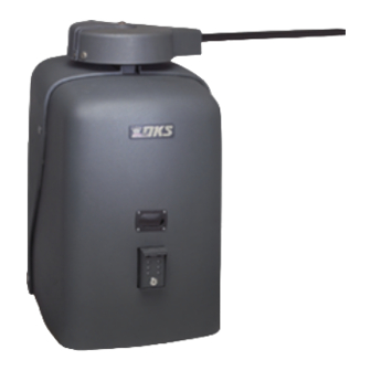
Heavy-Duty Vehicular Swing Gate Operator
Circuit Board
Serial Number
and Revision Letter:
Copyright 2012 DoorKing, Inc. All rights reserved.
Series 6550
Series 6550
Series 6550
6550-065-A-4-12
Copyright 2009 DoorKing, Inc. All rights reserved.
TM
Advertisement
Table of Contents
Troubleshooting

Related Manuals for DKS Series 6550


Summary of Contents for DKS Series 6550
- Page 1 Installation/Owner’s Manual Series 6550 Series 6550 Series 6550 Heavy-Duty Vehicular Swing Gate Operator Use this manual for circuit board 4405-010 Revision E or higher. 6550-065-A-4-12 Date Installed: Installer/Company Name: Circuit Board Serial Number Phone Number: and Revision Letter: Leave Manual with Owner Copyright 2012 DoorKing, Inc.
-
Page 3: Specifications
SPECIFICATIONS Use this manual for the Model 6550 operators with circuit board 4405-010 Rev E or higher ONLY. Class of Operation Model 6550 - UL325 Class I, II, III, IV Type of Gate Vehicular Swing Gates Only Entrapment Protection Primary - Inherent entrapment sensing system (Type A) Secondary - Provision for connection of a non-contact sensor (Type B1) Type Max Gate... -
Page 4: Table Of Contents
TABLE OF CONTENTS SPECIFICATIONS ASTM F2200 Standard for Gate Construction Important Safety Instructions Instructions regarding intended installation: Important Notices UL 325 Entrapment Protection Glossary Swing Gate Requirements Swing Gate Protection SECTION 1 - INSTALLATION 1.1 Underground Conduit Requirements 1.2 Concrete Pad 1.3 Type of Installations 11-12 1.4 Securing Operator to Pad... - Page 5 TABLE OF CONTENTS SECTION 4 - ENTRAPMENT AND SAFETY PROTECTION 4.1 UL 325 Terminal Description 4.2 Entrapment and Safety Protection Device Locations 4.3 Loop Detector Wiring SECTION 5 - MAIN TERMINAL WIRING 5.1 Terminal Description 5.2 Control Wiring SECTION 6 - OPERATING INSTRUCTIONS 6.1 AC Power Switch and Reset Button 6.2 Shutdown Conditions 29-30...
-
Page 6: Astm F2200 Standard For Gate Construction
ASTM F2200 Standard for Gate Construction Vehicular gates should be constructed and installed in accordance with ASTM F2200; Standard Specification for Automated Vehicular Gate Construction. For a copy of this standard, contact ASTM directly at 610-832-9585; service@astm.org; or www.astm.org. Important Safety Instructions WARNING - To reduce the risk of injury or death: 1. -
Page 7: Important Notices
• For gate operators utilizing contact sensors: 1. One or more contact sensors shall be located where the risk of entrapment or obstruction exist, such as at the leading edge, trailing edge, and post mounted both inside and outside of a vehicular horizontal slide gate. 2. -
Page 8: Ul 325 Entrapment Protection
UL 325 Entrapment Protection Class I Class II A vehicular gate operator (or system) intended for use in a A vehicular gate operator (or system) intended for use in a home of one-to four single family dwelling, or a garage or commercial location or building such as a multi-family parking area associated therewith. -
Page 9: Glossary
Glossary GATE - A moving barrier such as a swinging, sliding, raising, lowering, or the like, barrier, that is a stand-alone passage barrier or is that portion of a wall or fence system that controls entrance and/or egress by persons or vehicles and completes the perimeter of a defined area. -
Page 10: Swing Gate Requirements
Swing Gate Requirements The operator is intended for installation only on gates used for vehicles. Pedestrians must be supplied with a separate access opening. The pedestrian access opening shall be designed to promote pedestrian usage. Locate the gate such that persons will not come in contact with the vehicular gate during the entire path of travel of the vehicular gate. -
Page 11: Swing Gate Protection
Swing Gate Protection Non-contact Sensor Minimizes the potential Reverse Loop of the gate closing on Minimizes the potential of the gate vehicular or other traffic closing when a vehicle is present. that loops cannot sense. Number and placement of loops is See pages 23-24 for dependent on the application. -
Page 12: Section 1 - Installation
SECTION 1 - INSTALLATION Prior to beginning the installation of the swing gate operator, we suggest that you become familiar with the instructions, illustrations, and wiring guide-lines in this manual. This will help insure that your installation is performed in an efficient and professional manner compliant with UL 325 safety and ASTM F2200 construction standards. -
Page 13: Type Of Installations
1.3 Type of Installations Standard Installation Recommended for gates up to 25 feet opening 90°. 46” 14” 12” 17” 90° 38.5” 35” 2” 30” 36” 24” Concrete Pad 44” Concrete Pad Location Operator Installation Alternate Installation Recommended for gates up to 18 feet opening 90°. 42”... -
Page 14: Securing Operator To Pad
Compact Installation Recommended for gates up to 14 feet opening 90°. 34” 14” 12” 12” 90° 30” 29.5” 2” 26” 36” 24” Concrete Pad Concrete Pad Location 26” Operator Installation 1.4 Securing Operator to Pad Permanently attach the operator to the concrete pad using six (6) 3/8”... -
Page 15: Attach Gate Bracket
1.5 Attach Gate Bracket Release hub with release tool. DO NOT REMOVE HUB! Bolt crank arm to operator. Gate Bracket Slide elbow assembly on crank arm. Bolt control arm to gate bracket. Control Arm Slide control arm into elbow assembly. KEEP ARM ASSEMBLY LEVEL. -
Page 16: Determining Arm Lengths
1.6 Determining Arm Lengths Slide elbow assembly back and fourth, manually opening and closing gate until satisfied with the gate’s 90° open and fully closed positions. Mark and cut off excess arms. Secure arms to elbow assembly with 6 allen screws. Tighten hub and replace release tool. Install safety covers. -
Page 17: High Voltage Wire Run
2.1 High Voltage Wire Runs The distance shown in the chart is measured in Feet from the operator to the power source. If power wiring is greater than the maximum distance shown, it is recommended that a service feeder be installed. When large gauge wire is used, a separate junction box must be installed for the operator connection. -
Page 18: Bi-Parting Gates Wiring - Dual Gate Operators
2.3 Bi-Parting Gates Wiring - Dual Gate Operators Connect the Primary/Secondary operators together with DoorKing’s interconnection cable as shown (Different lengths sold separately). High voltage power and low voltage communications are supplied to the secondary operator by DoorKing’s UL approved cable that is run in a single conduit. Two conduits (High voltage and low voltage) will need to be provided to the secondary operator when NOT using DoorKing’s UL listed, wet environment interconnection cable. -
Page 19: Section 3 - Adjustments
SECTION 3 - ADJUSTMENTS The switch settings and adjustments in this chapter should be made after your installation and wiring to the operator(s) is complete. Whenever any of the programming switches on the circuit board are changed, power must be shut-off, and then turned back on for the new setting to take effect. -
Page 20: 4405 Circuit Board Descriptions And Adjustments
3.2 DIP-Switch Settings for 4405 Circuit Board The two DIP-switches located on the circuit board are used to program the operator to operate in various modes and to turn on or off various operating features. Whenever a switch setting is changed, power to the operator must be turned OFF and then turned back on for the new setting to take affect. - Page 21 3.2 Continued Switch Definitions SW 1 (Top 8 Switches) Typical Settings Must OPEN the primary operator’s gate upon initial AC power up and open command. If the FIRST open command Switch 1 begins to close the gate, turn AC power off and reverse this switch. Must OPEN the secondary operator’s gate upon initial AC power up and open command.
-
Page 22: Limit Sensors
3.3 Limit Sensors Important Limit Sensor Adjustment Note: CAUTION The hub must not slip It is very important NOT to cycle the gate operator during operation. Tighten before the limit sensors are in the correct position or DO NOT REMOVE HUB! bolt to stop any slipping. -
Page 23: Inherent Reverse Sensors Adjustment
3.4 Inherent Reverse Sensors Adjustment This vehicular gate operator is equipped with an inherent adjustable reversing sensor (Type A) used as the primary entrapment protection system according to UL 325 standards. The gate will reverse direction after “physically” encountering an obstruction in either the opening or closing gate cycle. -
Page 24: Secondary Current Sensor Adjustment
3.5 Secondary Current Sensor Adjustment (Dual Gates ONLY) The PRIMARY gate operator’s “secondary reversing sensor” uses a secondary current sensing device (Located only in the primary operator) to detect any obstructions “physically” encountered in the SECONDARY gate path when using dual gates. The secondary current sensor uses a sensing coil with a given number of turns through it to monitor the current flow into the secondary operator. -
Page 25: Section 4 - Entrapment And Safety Protection
SECTION 4 - ENTRAPMENT AND SAFETY PROTECTION Secondary Entrapment Protection Device: In addition to the inherent reversing sensor system, the Model 6550 has a 6-pin UL 325 terminal for the connection of photo sensors-Type B1 secondary entrapment protection device required by UL 325 standards. Entrapment protection devices must be installed to reduce the risk of injury. -
Page 26: Entrapment And Safety Protection Device Locations
4.2 Entrapment and Safety Protection Device Locations Typical UL Photo Sensor mounting height and distance away from gate. Opening-Direction Photo Sensors Closing-Direction Photo Sensors UL sensor mounted just above top of operator 5” or less Wall 21” Typical If this space is less than 16 inches, Non-Secure Side Secure Side secondary entrapment protection... -
Page 27: Loop Detector Wiring
• Loop detector wiring is shown for DoorKing 4.3 Loop Detector Wiring plug-in loop detectors. If other loop detectors are used, refer to the installation instructions supplied To help protect the operator from accidentally closing on vehicles with those detectors for wiring instructions. in the gate’s path, DoorKing highly recommends that loops and •... -
Page 28: Section 5 - Main Terminal Wiring
It MUST be mounted in the DANGER line-of-sight of the gate HIGH VOLTAGE! operator. (DKS P/N 1404-080) For dual operator applications ONLY. Allows the secondary reversing sensor to monitor the current flow into the secondary operator. See page 22 for more information. -
Page 29: Control Wiring
Stand-Alone Card Reader SW 2 Remote Alarm Reset Station Note: All stand-alone (DKS P/N 1404-080) MUST be mounted and telephone entry devices must in the line-of-sight of the gate operator. use a separate power source. Gate Tracker DoorKing Access Control System (Model 1833, 1835, 1837 or 1838) tracker system can be connected. -
Page 30: Section 6 - Operating Instructions
SECTION 6 - OPERATING INSTRUCTIONS IMPORTANT SAFETY INSTRUCTIONS WARNING - To reduce the risk of injury or death: 1. READ AND FOLLOW ALL INSTRUCTIONS. 2. Never let children operate or play with gate controls. Keep the remote control away from children. 3. -
Page 31: Shutdown Conditions
6.2 Shutdown Conditions Under various entrapment conditions the operator will assume either a soft or hard (alarm) shutdown. To determine what type of reset action is required, you will need to understand how the different entrapment conditions affect the gate operator. -
Page 32: Manual Gate Operation
Resetting a Hard Shutdown When the operator is in a hard shutdown condition (audio alarm activated or audio alarm “chirps” every 5 seconds), the only way to reset the gate operator and return it to normal operation is to activate the alarm reset input (auxiliary terminals 2 and 3). -
Page 33: Manual Release
Manual Release • Be sure that power is removed or shut-off prior to placing the gate operator in manual operation. Unlock the cover and rotate sliding door. Never attempt to manually push open any gate with an operator attached to it until you have verified that power to the operator has been shut-off. -
Page 34: Section 7 - Maintenance And Troubleshooting
SECTION 7 - MAINTENANCE AND TROUBLESHOOTING Inspection and service of this gate operator by a qualified technician should be performed anytime a malfunction is observed or suspected. High cycle usage may require more frequent service checks. 7.1 Maintenance When servicing the gate operator, always check any secondary (external) reversing devices (loops, photo eyes, etc.) for proper operation. -
Page 35: Troubleshooting
7.2 Troubleshooting Have a good VOM meter to check voltages and continuity. A Meg-Ohm meter capable of checking up to 500 meg-ohms of resistance is necessary to properly check the integrity of the ground loops. When a malfunction occurs, isolate the problem to one of three areas: 1) the operator, 2) the loop system, 3) the keying devices. - Page 36 Symptom Possible Solution(s) Gate will not reverse • Check ERD setting. when an obstruction • Make sure operator hub does not slip when gate encounters an obstruction. is encountered. Gate opens a short • Check the reversing sensitivity. distance, then stops •...
-
Page 37: Built-In Diagnostics
7.3 Built-in Diagnostics This gate operator is designed with built-in diagnostics that will alert you to potential or existing problems that the microproces- sor has detected. Specific fault conditions are checked and the operator will signal that a fault exist through the built-in alarm. Constant tone is heard when power is applied: This indicates that the limit switch wire harness is not connected to the circuit board. -
Page 38: Gearbox Shaft Extension Replacement
7.5 Gearbox Shaft Extension Replacement Crank Arm Hub Assembly Remove the TWO allen screws on bottom of hub to remove the complete hub assembly. Limit Sensors Collar Brass Bushing Gearbox Shaft Extension with 4 Keys Stainless Steel Washer Snap Ring Set Screws Gearbox Collar Remove the FOUR allen screws to remove the gearbox collar. -
Page 39: Model 6550'S Wiring Diagrams
Model 6550 1 HP 115 VAC Magnetic Magnetic Remote Terminal Close Open White Sensor Sensor Brown 1 HP Yellow Single-Phase Orange Orange Blue White Orange Yellow EXIT LOOP SELF TEST TIME DELAY REV SENSE REV SENSE SECONDARY PRIMARY REVERSE LOOP Current Sensor 4405 Power... - Page 40 Model 6550 1 HP 208 / 230 / 460 VAC Magnetic Magnetic Remote Terminal Close Open White Sensor Sensor Brown 1 HP Yellow Single-Phase Orange Orange Blue White Orange Yellow EXIT LOOP SELF TEST TIME DELAY REV SENSE REV SENSE SECONDARY PRIMARY REVERSE...
- Page 41 Model 6550 1 HP Secondary Operator Magnetic Magnetic Close Open Sensor Sensor 1 HP Single-Phase Blue White 6550-065-A-4-12...
-
Page 42: 6550-065
Installation/Owner’s Manual Series 6550 Series 6550 Series 6550 Heavy-Duty Vehicular Swing Gate Operator Use this manual for circuit board 4405-010 Revision E or higher. 6550-065-A-4-12 www.doorking.com DoorKing, Inc. 120 Glasgow Avenue Inglewood, California 90301 U.S.A. Phone: 310-645-0023 Fax: 310-641-1586 Copyright 2009 DoorKing, Inc. All rights reserved.
Need help?
Do you have a question about the Series 6550 and is the answer not in the manual?
Questions and answers