Table of Contents
Advertisement
Quick Links
Installation/Owner's Manual
Use this manual for circuit board 4502-010 Revision AA or higher.
EXTERNAL ENTRAPMENT PROTECTION MUST be
installed or the gate operator WILL NOT function.
P o
s t M
o u
n t
d M
W A
R N
IN
G
P a
M OV
SE
IN
RI
OU
G
GA
S IN
TE
era
Op
JU
CA
and
te
free
gat
RY
N
Do
of
e onl
OR
CA
US
or
not
peo
ple
y wh
en
DE
E
ope
allo
w
and
gat
AT
Do
rate
gat
chi
ldre
obs
tru
e are
a is
H
pat
not
e.
n to
ctio
in
h wh
sta
nd
pla
ns.
sig
ht
Rea
ile
gat
in
gat
y in
gat
CO
d ow
e is
e pat
e are
NF
OR
ner
mo
vin
h or
a
AN
SI/
MS
's
ma
g.
wa
lk
UL
-32
TO
nua
l and
thr
oug
CA
N/C
CE
RT
5
saf
h
SA
IFI
ED
ety
ins
VE
C2
2.2
TO
tru
HI
CU
NO
ctio
ns.
CL
LA
. 24
533
82
AS
S
R
GA
7
MO
TE
DE
OP
ER
L
AT
SE
RIA
HP
OR
L
VO
LTS
AM
PS
MA
X GA
PH
TE
AS
E
LO
Do
orK
AD
60
Hz
ing
, Inc
.,
Ing
lew
oo
d,
CA
Date Installed:
Installer/Company Name:
Phone Number:
Leave Manual with Owner
UL 325 Compliant
n t
o u
Copyright 2016 DoorKing, Inc. All rights reserved.
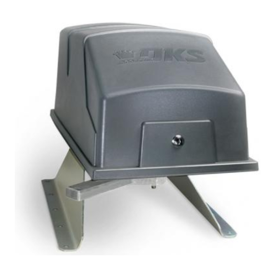
Vehicular Swing Gate Operator
Circuit Board
Serial Number
and Revision Letter:
Copyright 2009 DoorKing, Inc. All rights reserved.
Series 6300
Series 6300
6300-065-G-2-16
Advertisement
Table of Contents
Troubleshooting

Related Manuals for DKS 6300 Series


Summary of Contents for DKS 6300 Series
- Page 1 Installation/Owner’s Manual Series 6300 Series 6300 Vehicular Swing Gate Operator Use this manual for circuit board 4502-010 Revision AA or higher. 6300-065-G-2-16 EXTERNAL ENTRAPMENT PROTECTION MUST be installed or the gate operator WILL NOT function. s t M M OV S IN free e onl...
- Page 2 QUICK GUIDE: DIP-Switches See page 20 for descriptions about DIP-switches. When a switch setting is changed, power must be turned OFF and then turned back ON for the new setting to take affect. Every time the operator is powered up, the First open command will automatically set the open and close limits of the gate.
- Page 3 QUICK GUIDE: Main Terminal Descriptions See page 24 for main terminal wiring. DANGER HIGH VOLTAGE! • When gate is closed, input will open gate. SW 4 • When gate is open and auto close timer SW 4, switch 4 is turned ON, input will 115 VAC - Neutral re-set and hold timer.
- Page 4 SPECIFICATIONS Use this manual for the Model 6300 operator with circuit board 4502-010 Rev AA or higher ONLY. Class of Operation Model 6300 - UL325 Class I, II, III, IV Type of Gate Vehicular Swing Gates Only Inherent Entrapment Protection Device Inherent Reverse Sensor System (Type A) - Adjustment is NOT needed.
-
Page 5: Table Of Contents
TABLE OF CONTENTS QUICK GUIDE - DIP-SWITCHES and MAIN TERMINAL Quick Guide-1 & 2 Previous Page SPECIFICATIONS ASTM F2200 Standard for Gate Construction Important Safety Instructions Instructions regarding intended installation: Important Notices UL 325 Entrapment Protection Glossary Swing Gate Requirements Swing Gate Protection SECTION 1 - INSTALLATION Operator Position... -
Page 6: Astm F2200 Standard For Gate Construction
ASTM F2200 Standard for Gate Construction Vehicular gates should be constructed and installed in accordance with ASTM F2200; Standard Specification for Automated Vehicular Gate Construction. For a copy of this standard, contact ASTM directly at 610-832-9585; service@astm.org; or www.astm.org. Important Safety Instructions WARNING - To reduce the risk of injury or death: 1. -
Page 7: Important Notices
• For gate operators utilizing contact sensors: 1. One or more contact sensors shall be located where the risk of entrapment or obstruction exist, such as at the leading edge, trailing edge, and post mounted both inside and outside of a vehicular horizontal slide gate. 2. -
Page 8: Ul 325 Entrapment Protection
UL 325 Entrapment Protection UL 325 Classifications Authoriz ed Personn el ONLY Class I - Residential Class III - Industrial/Limited Access Vehicular Gate Operator Vehicular Gate Operator A vehicular gate operator (or system) intended for use in garages A vehicular gate operator (or system) intended for use in an or parking areas associated with a residence of one-to four single industrial location or building such as a factory or loading dock families. -
Page 9: Glossary
Glossary GATE - A moving barrier such as a swinging, sliding, raising, lowering, or the like, barrier, that is a stand-alone passage barrier or is that portion of a wall or fence system that controls entrance and/or egress by persons or vehicles and completes the perimeter of a defined area. -
Page 10: Swing Gate Requirements
Swing Gate Requirements The operator is intended for installation only on gates used for vehicles. Pedestrians must be supplied with a separate access opening. The pedestrian access opening shall be designed to promote pedestrian usage. Locate the gate such that persons will not come in contact with the vehicular gate during the entire path of travel of the vehicular gate. -
Page 11: Swing Gate Protection
Swing Gate Protection Non-contact Sensor Minimizes the potential of the gate closing on vehicular or other traffic that loops cannot sense. Monitored device helps protect against Reverse Loop entrapment. Minimizes the potential of the gate closing when a vehicle is present. Warning Signs Number and placement of loops is Permanently mounted... -
Page 12: Section 1 - Installation
SECTION 1 - INSTALLATION Prior to beginning the installation of the swing gate operator, we suggest that you become familiar with the instructions, illustrations, and wiring guide-lines in this manual. This will help insure that your installation is performed in an efficient and professional manner compliant with UL 325 safety and ASTM F2200 construction standards. -
Page 13: Post Mount Or Pad Mount Base Assembly
1.2 Post Mount or Pad Mount Base Assembly 1 1/2” bolts through the main gear bracket mounting holes. Hardware for Post Mount: Post Support Base (6) 1 1/2 inch bolts. For support plate. Screw the posts to the support (4) Non-slip nuts. For existing plate and mount into concrete threaded studs on bottom of 6300. -
Page 14: Underground Conduit Requirements
1.3 Underground Conduit Requirements Primary Secondary Operator Operator Position Position DoorKing’s Primary/Secondary Interconnection Cable (Dual Operator Application Only) (Secondary Operator AC Power and Communication wires) External Safety Devices, Controls and P.A.M.S. Wires (Low Voltage wire insulation) Loop Lead-In Wires (Low Voltage wire insulation) AC Input Power (High Voltage wire insulation) Concrete Pad Sweeps... -
Page 15: Post Mount
1.5 Post Mount Note: 2” thick Important Note: These post mount measurements will gate Illustrated. ONLY work when the operator is positioned using the “1.1 Operator Position” measurements on page 8. Mount the post base into the concrete 90° before installing the operator. Open Gate The post mount installation will allow Concrete... -
Page 16: Manually Adjust The Open And Closed Gate Positions
1.7 Manually Adjust the Open and Closed Gate Positions DO NOT power up the operator to set the open and closed gate positions. The first time the operator is powered up and cycled, it will automatically set the open and close limits. To do this, the arms MUST already be in the correct configuration. Closed Arms Position Open Arms Position Closed Gate... -
Page 17: Entrapment Protection Installation Required
1.9 Entrapment Protection Installation REQUIRED A monitored photo sensor (Type B1) or monitored reversing edge (Type B2, see next page) MUST be installed or operator WILL NOT function. Monitored OPEN Photo Sensor Mounting Position Monitored CLOSE Photo Sensor Mounting Position UL sensor mounted just above top of operator 5”... - Page 18 1.9 Continued A monitored reversing edge (Type B2) or a monitored photo sensor (Type B1, see previous page) MUST be installed or operator WILL NOT function. Edge Transmitter OPTIONAL wireless transmitter can be used. Monitored Reversing Edge Typical Monitored Reversing Edge mounted on end of gate. Reversing Edge Mointored Sensor Note: Potential...
-
Page 19: Gates Opening Wider Than
1.10 Gates Opening Wider Than 90° The installation of an operator opening gates wider that 90° is the same for sections 1.3 through 1.9 except the operator and concrete pad will be in a different position. Individual requirements can be calculated following this 105° opening sample. Arm Assembly Connecting arm’s pivot point measurement 62.25”... -
Page 20: Section 2 - Ac Power To Operator(S)
SECTION 2 - AC POWER TO OPERATOR(S) Before attempting to connect any wiring to the operator, be sure that the circuit breaker in the electrical panel is in the OFF position. Permanent wiring must be installed to the operator as required by local electrical codes. It is recommended that a licensed electrical contractor perform this work. -
Page 21: Bi-Parting Gates Wiring - Dual Gate Operators
2.3 Bi-Parting Gates Wiring - Dual Gate Operators Connect the Primary/Secondary operators together with DoorKing’s interconnection cable as shown (Different lengths sold separately P/N 2600-75x). High voltage power and low voltage communications are supplied to the secondary operator by DoorKing’s UL approved cable Blue that is run in a single conduit. -
Page 22: Section 3 - Adjustments
SECTION 3 - ADJUSTMENTS The switch settings and adjustments in this chapter should be made after your installation and wiring to the operator(s) is complete. Whenever any of the programming switches on the circuit board are changed, power must be shut-off, and then turned back on for the new setting to take effect. -
Page 23: Dip-Switch Sw 3 & Sw 4 Settings
3.2 DIP-Switch SW 3 & SW 4 Settings The two DIP-switches located on the circuit board are used to program the operator to operate in various modes and to turn on or off various operating features. Whenever a switch setting is changed, power to the operator must be turned OFF and then turned back on for the new setting to take affect. -
Page 24: Dip-Switch Descriptions
3.3 DIP-Switch Definitions SW 4 (Top 8 Switches) These work in conjunction with each other and determine when the relay on the board will be activated. This relay can be used as a Switches 1-2 switch for various functions such as illuminating a warning light when the gate is moving, or turning on a green light when the gate is full open. This relay is NOT available for these uses if it is being used for the SHADOW loop function. -
Page 25: Automatic Open / Close Limit Adjustment
3.4 Automatic Open / Close Limit Adjustment The 6300’s open/close limits DO NOT have to be physically adjusted. The gate open and close positions are determined by the physical stop “Flange” on the elbow assembly (See below). The arms MUST already be in the correct closed configuration (See Section 1.7 on page 12). -
Page 26: Clutch Adjustment
3.5 Clutch Adjustment This vehicular gate operator is equipped with an inherent adjustable clutch “Type C” that can be used as an entrapment protec- tion device. If the clutch is intended to be used as such, it must be adjusted to NOT open or close the gate with a sustained force greater than 40 lbs at the leading edge of the gate, except for the first 10 degrees of arc travel after any initiation of movement. -
Page 27: Section 4 - Wiring
SECTION 4 - WIRING 4.1 Main Terminal Description DANGER HIGH VOLTAGE! • When gate is closed, input will open gate. SW 4 • When gate is open and auto close timer SW 4, switch 4 is turned ON, input will 115 VAC - Neutral re-set and hold timer. -
Page 28: Control Wiring
Antenna mounted 4.2 Control Wiring outside operator cover. (2) Two 115 VAC Convenience Outlets Coax Antenna Kit P/N 1514-073 Important: Controls intended for user activation must be located at least six (6) feet away from any moving part of the gate and where the user is prevented from reaching over, under, around or through the gate to operate the controls. -
Page 29: Auxiliary Terminal Wiring
4.3 Auxiliary Terminal Wiring DoorKing Access Control System (Model 1833, 1835, 1837 or 1838) tracker system can be connected. This system can keep track of gate operator cycle count, shorted inputs, loop detector problems, any forced entry attempts, if the 24 VAC Power 24 VAC gate has struck anything during the open or close cycle, power... -
Page 30: Loop Detector Wiring
4.4 Loop Detector Wiring To help protect the operator from accidentally closing on vehicles • Loop detector wiring is shown for DoorKing in the gate’s path, DoorKing highly recommends that loops and plug-in loop detectors. If other loop detectors are loop detectors be installed. -
Page 31: Section 5 - Operating Instructions
SECTION 5 - OPERATING INSTRUCTIONS IMPORTANT SAFETY INSTRUCTIONS WARNING - To reduce the risk of injury or death: 1. READ AND FOLLOW ALL INSTRUCTIONS. 2. Never let children operate or play with gate controls. Keep the remote control away from children. 3. -
Page 32: Shutdown Conditions
5.2 Shutdown Conditions Under various entrapment conditions the operator will assume either a soft or hard (alarm) shutdown. To determine what type of reset action is required, you will need to understand how the different entrapment conditions affect the gate operator. -
Page 33: Manual Gate Operation
Resetting a Hard Shutdown When the operator is in a hard shutdown condition (audio alarm activated or audio alarm “chirps” every 5 seconds), the only way to reset the gate operator and return it to normal operation is to activate the alarm reset input (auxiliary terminals 2 and 3). -
Page 34: Manual Release
FAIL-SAFE Manual Operation The FAIL-SAFE manual operation system is the most reliable and safest method for placing an automated gate in manual operation and is the preferred method of emergency gate operation under worse case conditions by many Fire Chiefs and Building Inspectors and is typically used in CLASS I and CLASS II applications. This system requires no keys, cranks or tools for manual gate operation and is completely automatic. -
Page 35: Section 6 - Maintenance And Troubleshooting
SECTION 6 - MAINTENANCE AND TROUBLESHOOTING Inspection and service of this gate operator by a qualified technician should be performed anytime a malfunction is observed or suspected. High cycle usage may require more frequent service checks. 6.1 Maintenance When servicing the gate operator, always check any (external) safety devices (loops, photo sensors, etc.) for proper operation. If external safety devices cannot be made operable, do not place this operator in service until the malfunction can be identified and corrected. -
Page 36: Troubleshooting
6.2 Troubleshooting Have a good VOM meter to check voltages and continuity. A Meg-Ohm meter capable of checking up to 500 meg-ohms of resistance is necessary to properly check the integrity of the ground loops. When a malfunction occurs, isolate the problem to one of three areas: 1) the operator, 2) the loop system, 3) the keying devices. - Page 37 6.2 Troubleshooting Continued Symptom Possible Solution(s) • Check that the clutch is adjusted properly and is not slipping. Gate opens a short • Disconnect the gate from the gate operator and check that the gate swings freely without any binding. distance, then stops •...
-
Page 38: Accessory Items
6.3 Accessory Items UL 325 Monitored Entrapment Protection Devices available for the model 6300 swing gate operator. Type B2 Contact Sensors (Photo Cell) Miller Edge Sensing Edges - all models with a T2 (resistive) termination. Miller Edge Monitored Gate Link Model MGL-K20 Type B1 Non-contact Sensors (Reversing Edge) Miller Edge Reflective-Guard Model RG Miller Edge Prime-Guard Model PG... -
Page 39: Model 6300'S Wiring Diagrams
Model 6300 1/2 HP 115 VAC 1/2 HP 50uf Capacitor Magnetic Blue Limit Sensor Blue White Ground Ground SECONDARY OPERATOR MOTOR Blue EXIT LOOP Yellow Brown 4502-010 KEY SWITCH DATA POWER SW 4 SAFETY SW 3 LOOP Orange White White Yellow White Black... - Page 40 Model 6300 1 HP 115 VAC 1 HP Magnetic Limit Sensor Blue White Ground Ground SECONDARY OPERATOR MOTOR Blue EXIT LOOP Yellow Brown 4502-010 KEY SWITCH DATA POWER SW 4 SAFETY SW 3 LOOP Orange White White Yellow White Black Convenience Outlets Chassis Ground...
- Page 41 Model 6300 1/2 HP Secondary Operator Magnetic Limit Sensor 8. Gray 1/2 HP Orange 7. Orange Brown 6. Brown Yellow 5. Yellow 4. Purple White White 3. White Blue Blue 2. Blue Ground 1. Red Blue 50uf Capacitor Model 6300 1 HP Secondary Operator Magnetic Limit Sensor 8.
-
Page 42: 6300-065
Installation/Owner’s Manual Series 6300 Series 6300 Vehicular Swing Gate Operator Use this manual for circuit board 4502-010 Revision K or higher. 6300-065-G-2-16 For operators manufactured July 2011and later. www.doorking.com DoorKing, Inc. 120 S. Glasgow Avenue Inglewood, California 90301 U.S.A. Phone: 310-645-0023 Fax: 310-641-1586 Copyright 2009 DoorKing, Inc.
Need help?
Do you have a question about the 6300 Series and is the answer not in the manual?
Questions and answers