
Subscribe to Our Youtube Channel
Related Manuals for Morgana DigiCreaser


Summary of Contents for Morgana DigiCreaser
- Page 1 DigiCreaser HAND FED DOCUMENT CREASING MACHINE OPERATORS MANUAL Morgana Systems Limited United Kingdom Telephone: ( 01908 ) 608888 Facsimile: ( 01908 ) 692399 Website: www.morgana.co.uk 2012 ISSUE 6 OCTOBER 70-087...
-
Page 2: Table Of Contents
INDEX INTRODUCTION The Morgana Digicreaser PAGE SAFETY Do’s & Don’ts THE DIGICREASER Labelled Photograph THE CONTROLS The control panel Features on the control panel QUICK START GUIDE OPERATING THE DIGICREASER Setting the machine Programming the machine Reading stored programmes Paper jamming... -
Page 3: Introduction
The Morgana Digicreaser is a fully automatic, after feeding, creasing system designed for use with both conventional litho and digital printers. The Digicreaser is capable of creasing sheet sizes to a maximum of 630mm x 330mm (24.8” x 13”) and weights up to 400gsm. -
Page 4: Safety Do's & Don'ts
Safety Do’s & Don’ts Safety Do’s & Don’ts Do - read this operator manual fully before operating the machine. Do - operate with the designated AC current only. Use an exclusive outlet, as overloading may cause fire or an electric shock. Do - install the power cord out of the way to avoid a tripping hazard. - Page 5 DigiCreaser BLANK PAGE SYSTEM Page 5...
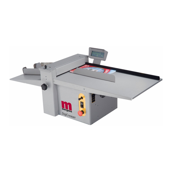
- Page 6 DIGICREASER Digicreaser HAND FED DOCUMENT CREASING MACHINE Key to photograph below Control Panel Back stop RH Roller tilt handle Fuses Fixed side lay Stacker assembly Stacker Guide LH Roller tilt knob The display unit 12 Stacker Guide RH Exit Guard...
-
Page 7: The Controls
DigiCreaser THE CONTROLS The Display Unit and the Switches on the Control Panel allow the operator to read, edit, create and initiate numerous creasing programs within the memory. The Control Panel houses the Selection Switch, System Switch, and an industry standard Emergency Stop switch which will stop all power going to the machine when activated. -
Page 8: Quick Start Guide
Quick Start Guide Setting the machine Place the stock to be creased onto the loading table against the fixed side lay. Position the adjustable side lay so that the gap between the paper stack and the side lay is approximately 0.5mm (1/64 inch) Turn the Emergency Stop button clockwise to switch the power on. - Page 9 DigiCreaser Quick Start Guide Move the selection switch to the left to select the Tens , or to the right to select Decimals . The Tens Decimals (whichever has been selected) can then be adjusted by rotating the Selection Switch, (clockwise to increase or anti-clockwise to decrease).
-
Page 10: Setting The Machine
Operating the Digicreaser Setting the Adjustable Side Lay Place the paper stack on to the loading table and slide up to the fixed side lay. Position the adjustable side lay up towards the paper stack, allow a gap of approx. -
Page 11: Programming The Machine
DigiCreaser Operating the Digicreaser Programming the machine Switch the power ‘on’ by turning the Emergency stop button clockwise to release the safety latch. The display is now switched on. Setting the crease positions Move the selection switch up, one click at a time, until the start up menu is displayed as shown below. -
Page 12: Reading Stored Programmes
Operating the Digicreaser Setting the Speed (High Speed or Low Speed) 4. (i) Move the selection switch to the right to select Setup (ii) Move the selection switch to the right again to select More (iii) Move the selection switch up or down to select... -
Page 13: The Stacker Assembly
DigiCreaser The Stacker Assembly The stacker unit on the Digicreaser is used to catch the sheets once they have been creased or perforated. Setting the Stacker assembly Assemble the stacker unit to the machine as shown in fig 13.1 below. - Page 14 The Stacker Assembly Whilst the sheet is between the two guides on the stacker bed, set the distance between the top of the sheet and the backstop flanges to approximately 5mm. For shorter sheets, the back stop can be used (as shown in FIG 13.1 to adjust the position of the paper stack.
-
Page 15: Perforating
DigiCreaser Perforating Once the machine is set- up, the Digicreaser can be used to perforate or crease. Note Perforating and creasing can be carried out simultaneously. However, if any adjustment is made to the roller tilt mechanism in order to compensate for the perforation line being ’out of square’, this may effect the accuracy of the crease. -
Page 16: Setting The Machine
Perforating All of the blades and anvils are supplied with fixings. *Perforator stripper Standard Part Number 78-013 *It is recommended that for multiple perforations, a separate perforator stripper is used for every perforating blade set fitted in the creasing unit. Setting the machine Turn the mains supply to the machine ‘off’. - Page 17 DigiCreaser Perforating 11. Mount the other anvil ensuring that they have matched on the drive hub. Secure the anvil to the hub ensuring not to over tighten grub screw as shown in fig 16.2. 12. Slide the drive hub towards the perforating drive wheel until there is a clearance of 0.5mm.
-
Page 18: The Blade Assembly
The Blade Assembly Adjusting the blade pressure (no paper required) 1. (i) Switch the power ‘on’ by turning the Emergency stop button clockwise to release the safety latch. The display is now switched on and will show the start up menu as shown below. -
Page 19: Setting The Blade Alignment
Digicreaser The Blade Assembly Adjusting the blade alignment It is extremely important that the blade and anvil assembly within the creasing unit is correctly aligned. Misalignment of the blade or anvil can lead to damaged profiles and subsequently poor quality creasing so it must, therefore, be corrected immediately. - Page 20 Replacing Blade Set Before removing the blade assembly, ensure that the lower blade / anvil is NOT at ‘top dead centre’, Switch the machine off. Remove the stacker unit and lift the exit guard. Using a 6mm allen key, loosen the socket Blade Extractor Tools head screws located inside the blade adjustment cams.
-
Page 21: Spares
DigiCreaser Replacing Blade Set FIG 21.1 11. Push the exit guard down and replace the stacker assembly before operating the machine. 12. Switch the machine on and test the crease for form. If the pressure and the alignment of the crease is not to a satisfactory level, see pages 19 –20 to adjust the creasing line. -
Page 22: Trouble Shooting
Trouble Shooting Paper crease out of square • Check that the sheets are all square and exactly the same size before loading the stack on to the table. • Check that the roller tilt mechanism is correctly set and locked in position. •... - Page 23 DigiCreaser Trouble Shooting Control panel reads Overlap - Probable Cause - Double Sheet • If the machine is ‘cutting out’ and the control panel reads Overlap - Probable Cause - Double Sheet check that the machine is not feeding multiple sheets.
-
Page 24: Dispatch Kit
7-95-12 DISPATCH KIT ITEM PART NUMBER DESCRIPTION OPERATORS MANUAL - 70-087 DIGICREASER 72-026 QUICK START CHART 90-018 ROLLER CLEANING KIT POWER CORD - CEE22 TO 3 PIN (UK) 613-316 SCREW - SOCKET CAP HEAD - M3 x 6 LG 403-01-030-006 409-01-040-004 SCREW - SKT. -
Page 25: Accessories & Options
DigiCreaser ACCESSORIES AND OPTIONS ITEM PART NUMBER DESCRIPTION 1-99-10 PERFORATING BLADE SET 20T (Card) 1-99-12 PERFORATING BLADE SET 28T (Single sheets) 1-99-41 PERFORATING BLADE SET 56T (Fine perforations) 1-99-35 ANVIL SET USED WITH ABOVE BLADE SETS 7-05-14 FLOOR STANDING BASE ACCESSORIES.. -
Page 26: Recommended Spares
RECOMMENDED SPARES PART NUMBER DESCRIPTION 613-365 EMERGENCY STOP SWITCH 652-011 SYSTEM SWITCH 144-04-04 JOYSTICK AND LEAD ASSEMBLY 75-347-01 CONTROL PCB ASSEMBLY 125-21-02 DUAL STEPPER DRIVE PCB ASSEMBLY 75-210-05 LCD DISPLAY UNIT (4 x 20) AND LEAD ASSEMBLY 655-014 PSU - SWITCH MODE - 5V (Used on Machines:- Serial Nos. - Page 27 DigiCreaser RECOMMENDED SPARES PART NUMBER DESCRIPTION NOTE..The items listed above represent parts which are subject to wear, loss, or accidental damage, and is included for your guidance only. Replacement of parts fitted to your machine require specialist knowledge and should therefore be entrusted to your dealer.
- Page 28 PRODUCT RECYCLING & DISPOSAL European Union Disposal Information for Commercial Users Application of this symbol on your equipment is confirmation that you must dispose of this equipment in compliance with agreed national Procedures. In accordance with European legislation end of life electrical and electronic equipment subject to disposal must be managed within agreed procedures.
- Page 29 DigiCreaser SYSTEM Page 29...
Need help?
Do you have a question about the DigiCreaser and is the answer not in the manual?
Questions and answers