
Related Manuals for Morgana AutoCreaser Pro 50


Summary of Contents for Morgana AutoCreaser Pro 50
- Page 1 AutoCreaser Pro 50 (CB/UL) DOCUMENT CREASING MACHINE OPERATORS MANUAL Morgana Systems Limited United Kingdom Telephone: ( 01908 ) 608888 Facsimile: ( 01908 ) 692399 Website: www.morgana.co.uk JANUARY 2013 ISSUE 4 70-171...
-
Page 2: Table Of Contents
INDEX INTRODUCTION PAGE 3 The Morgana AutoCreaser Pro 50 SAFETY Do’s & Don’ts THE AUTOCREASER Pro 50 Labeled Photograph THE CONTROLS The switch panel Features on the switch panel QUICK START GUIDE OPERATING THE AUTOCREASER Pro 50 Setting the machine... -
Page 3: Introduction
The Morgana AutoCreaser Pro 50 is a fully automatic suction feeding creasing system designed for use with both conventional litho and digital printers. The feed on the AutoCreaser Pro 50 can also be manually operated for use with heavy stock, very small or very large sheets, embossed or even irregular sheets. -
Page 4: Safety Do's & Don'ts
Safety Do’s & Don’ts Safety Do’s & Don’ts REGLES DE SECURITE : « A FAIRE » ET « A NE PAS FAIRE » Do - read this operator manual fully before operating the machine. Lire ce mode d'emploi avant d'utiliser la machine. Do - operate with the designated AC current only. - Page 5 AutoCreaser Pro 50 Warning Labels Do - be aware of any finger traps and rotating parts when operating the machine. Attention au risque de se coincer les doigts, et aux pièces en mouvement lors du fonctionnement de la machine. Do - read this operator manual fully before operating the machine.
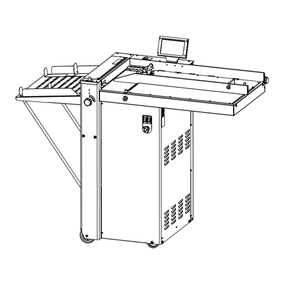
- Page 6 AUTOCREASER Pro 50 AutoCreaser Pro 50 DOCUMENT CREASING MACHINE Key to photograph below Roller tilt handle Adjustable side lay Switch Panel Stacker assembly 8 Back Stop Fuses Suction slot knob 9 Fixed side lay Gap Set Knob and Lever Touchscreen...
- Page 7 AutoCreaser Pro 50 THE CONTROLS THE SWITCH PANEL The Switch Panel houses the Compressor switch, System switch, and an industry standard Emergency Stop switch which will stop all power going to the machine when activated. Compressor Switch System Switch Emergency Stop Switch...
- Page 8 THE CONTROLS BLANK PAGE Page 8 CREASING...
-
Page 9: Quick Start Guide
Select the green tick icon only if you have been trained to operate this machine. If you have not been trained to operate this machine and you select the green tick icon, Morgana Systems Ltd accept no responsibility for personal injury, damage to the machine or damage to materials being processed by the machine. - Page 10 Quick Start Guide The touch screen is laid out into 3 main areas as shown below: Status of Setting machine & page data entry area. Also used for quick links to setting pages. Tabs to enable switching between setting pages - choose either Paper Settings, Crease Setting, Store or Tools Settings Pages.
- Page 11 AutoCreaser Pro 50 Quick Start Guide Crease settings Pages. To get to the crease setting page click the lower tab from the status area. If you have selected a predefined standard crease type from the paper settings page the crease positions will be set for you. These positions can be fine tuned by ±...
- Page 12 Quick Start Guide Creasing turned off - Greyed out areas are unselectable. Status area will show creasing is off with red icon Page 12 CREASING...
- Page 13 AutoCreaser Pro 50 Quick Start Guide Run Job Click to start machine with settings currently shown - you will receive a notification if system switch is not on. Press again to stop Job System Switch Not On Push System Switch down to start the machine.
- Page 14 Quick Start Guide Cover Crease Mode. 1. Select the Paper Settings Tab. 2. Enter the Paper Length and then select the Cover Crease button. Cover Crease button Paper Length 3. Select the Crease Settings Tab. Spine Offset Spine Width Hinge Distance Arrow Button 4.
- Page 15 AutoCreaser Pro 50 Quick Start Guide 6. Enter the Hinge Dimension. Hinge Dimension 7. Select the arrow button to highlight the Spine Offset and the Spine Width dimensions. 8. Run the sheets of paper through the machine to make the Spine creases.
- Page 16 Quick Start Guide Status Screen Currently selected Vacuum Suck setting - for stream Paper length - input from Clicking in this area will take you setting choose selection 2 the paper setting screen to the paper setting page Currently selected fold type - can be one of the Lead Edge Sensor Strength, following.
- Page 17 AutoCreaser Pro 50 Quick Start Guide The Status Screen will on occasions be replaced with an Input Calculator Screen as shown below. Pre - set Paper sizes for quick Pre - set Batch sizes for quick insertion – Standard sizes for insertion.
- Page 18 Use speed setting 1 or 2 for troublesome stocks, or to synchronise the speed of the AutoCreaser to a Morgana Autofold Pro, when they are used together. Click on Up Arrow to put Anvil into Top...
- Page 19 AutoCreaser Pro 50 Quick Start Guide Touch Screen Calibration. Switch the mains power on and wait for the main screen to appear before commencing to check the horizontal and vertical position of the display. The position of the display within the surround is achieved by operating the button...
- Page 20 Operating the Autocreaser Pro 50 Setting the Machine Adjusting the Paper Gate Set the height of the Paper Gate to approximately two thicknesses of paper, by turning the disc j. An excessive gap is a most likely cause of double sheet feeding.
- Page 21 AutoCreaser Pro 50 Operating the Autocreaser Pro 50 Setting the Adjustable Side Lay Place the paper stack on to the loading table and slide up to the fixed side lay and paper gate. Release the clamps located at each end of the side lay and slide up towards the paper stack as demonstrated in fig 8.1.
- Page 22 Operating the Autocreaser Pro 50 Setting the Roller Tilt Mechanism The roller tilt mechanism has been designed to compensate for when the creasing position on the sheet is not square. This could be due to an inaccuracy in the media or if the roller tilt mechanism has been incorrectly set.
- Page 23 AutoCreaser Pro 50 Operating the Autocreaser Pro 50 FIG 10.1 Set Feed The length of suction on the sheet of paper being fed can be adjusted by setting the feed type as follows:- Select 1 for short suck, select 2 for continuous suck (stream feeding).
- Page 24 Operating the Autocreaser Pro 50 etting the infeed roller gap set The gap between the infeed rollers must be adjusted to suit the stock being used. The gap set can be adjusted as follows:- 1. Place a sample sheet of the stock to be used onto the feed bed.
- Page 25 AutoCreaser Pro 50 Operating the Autocreaser Pro 50 SYSTEM Page 25...
-
Page 26: Programming The Machine
Operating the Autocreaser Pro 50 Programming the machine Switch the power ‘on’ by turning the Emergency stop button clockwise to release the safety latch. Setting the page length Set the page length of the paper as described on page 10. - Page 27 AutoCreaser Pro 50 Operating the Autocreaser Pro 50 Keyboard for entering job name. Delete all characters Delete last character to save click save icon job to store Save confirmation screen. To confirm saving of Job click here. Search for current jobs to load or modify.
- Page 28 Operating the Autocreaser Pro 50 Toggle between search Jobs matching results &full list of characters in text box jobs will be shown in this area - selecting job from this area will show job settings in the right hand status area.
-
Page 29: Setting The Machine
AutoCreaser Pro 50 Operating the Autocreaser Pro 50 Delete job confirmation screen. Tocancel deletion of Job press here. To confirm deletion of Job press here. Running the machine Run the job as described on page 13. The machine will complete its creasing operation if a sheet has already been fed through the paper gate. - Page 30 The Stacker Assembly The stacker unit on the machine is used to catch the sheets once they have been creased or perforated. Setting the Stacker assembly Assemble the stacker unit to the machine as shown in fig 13.1 below. Important Ensure that the stacker unit has been assembled to the machine properly.
- Page 31 AutoCreaser Pro 50 The Stacker Assembly Whilst the sheet is between the two guides on the stacker bed, set the distance between the top of the sheet and the backstop flanges to approximately 5mm. For shorter sheets, the back stop can be used (as shown in FIG 13.1) to adjust the position of the paper stack.
-
Page 32: Spares
Perforating Once the machine is set-up, the Autocreaser Pro 50 can be used to perforate or crease. Note Perforating and creasing can be carried out simultaneously. However, if any adjustment is made to the roller tilt mechanism in order to compensate for the perforation line being ’out of square’, this may effect the accuracy of the crease. - Page 33 AutoCreaser Pro 50 Perforating All of the blades and anvils are supplied with fixings. *Perforator stripper 78-013 Standard Part Number *It is recommended that for multiple perforations, a separate perforator stripper is used for every perforating blade set fitted in the creasing unit.
- Page 34 Perforating Mount the other anvil ensuring that they have matched on the drive hub. Secure the anvil to the hub ensuring not to over tighten grub screw as shown in fig 16.2. Slide the drive hub towards the perforating drive wheel until there is a clearance of 0.5mm.
- Page 35 AutoCreaser Pro 50 The Blade Assembly Adjusting the blade pressure (no paper required) 1. (i) Switch the power ‘on’ by turning the Emergency stop button clockwise to release the safety latch. (ii) Select the Tools tab at the bottom of the touch screen, the display will change to that shown below.
- Page 36 The Blade Assembly Adjusting the blade alignment It is extremely important that the blade and anvil assembly within the creasing unit is correctly aligned. Misalignment of the blade or anvil can lead to damaged profiles and subsequently poor quality creasing so it must, therefore, be corrected immediately. If the blade set is misaligned, the media being driven will be subject to scoring or even Please note that to avoid damage to the tearing at any point along the crease line.
- Page 37 AutoCreaser Pro 50 Replacing Blade Set Before removing the blade assembly, ensure that the lower blade / anvil is NOT at ‘top dead centre’, Switch the machine off. Remove the stacker unit and lift the exit guard. Blade Extractor Tools...
- Page 38 The Blade Assembly 9. Slide the new blade set into the slots of the creasing unit as shown in fig. 21.1. FIG 21.1 NOTE. The blade set can be fitted with the ANVIL at the bottom or with the ANVIL at the top. The blade set is supplied from the factory with the ANVIL at the bottom as shown in FIG22A.
- Page 39 However, components within the blade set can not be ordered separately ie single blade or anvil. The following Blade sets are supplied with the Autocreaser Pro 50 as standard. Standard Blade set Part number 76 - 237 - 02 Consisting of a standard blade and anvil, blade brushes, blade links and alignment bolts.
-
Page 40: Trouble Shooting
Trouble Shooting Paper crease out of square Check that the sheets are all square and exactly the same size before loading the stack on to the table. Check that the roller tilt mechanism is correctly set and locked in position. Check that the adjustable side lay has been correctly positioned ie. - Page 41 AutoCreaser Pro 50 Trouble Shooting Check that the air distribution has been correctly set. Check that the air separation has been set high enough to feed the sheets. For heavy stocks, very small or very large sheets, embossed or even irregular stock, it may be required to feed the sheets manually - see page 29 for instructions.
- Page 42 Trouble Shooting Error Screens Sheet did not arrive. If the machine stops and error message 01 is displayed on the touch screen, this indicates that the paper did not arrive at the end of the suck process; so the machine timed out.
- Page 43 AutoCreaser Pro 50 Trouble Shooting Error Screens (Continued) Blade Not Home If the machine stops and error message 04 is displayed on the touch screen, this indicates that the lower blade / anvil has not made contact with the HOME switch.
- Page 44 Trouble Shooting Error Screens (Continued) Clean Lead Edge Sensor - Warning Screens. 1. The Clean Lead Edge Sensor warning screen, shown below, will appear when the Run button is pressed and the strength of the Lead Edge Sensor Beam is at about 50% (i.e.
- Page 45 AutoCreaser Pro 50 Trouble Shooting Error Screens (Continued) Lead Edge Sensor Cleaning. Select the Tools menu on the Touchscreen Display, and then select the clean sensor icon The screen now shown is a visual indication of the strength of the Lead Edge Sensor beam.
-
Page 46: Dispatch Kit
To clean the lead edge sensors open the exit guard to expose the blade set. Using the Sensor Cleaning Brush (Morgana part number 601-185), supplied in the dispatch kit, insert the brush between the blade brushes and the top and bottom blades to reach the upper and lower lead edge sensors. - Page 47 AutoCreaser Pro 50 Trouble Shooting Recommended weekly operator maintenance Clean all sensors Clean in feed rollers and output drive hubs using the cleaning kit provided (Cleaning kit part number 90-018) Remove and clean the blade assembly With the blade assembly removed, clean the slots and surrounding area within the creasing unit.
- Page 48 7-95-29 DISPATCH KIT ITEM PART NUMBER DESCRIPTION OPERATORS MANUAL - 70-171 AUTOCREASER Pro 50 (CB) 90-018 ROLLER CLEANING KIT 650-040 POWER CORD CE UK C19 3Pin 16A 2.5Mtrs. SCREW - SOCKET CAP HEAD - M3 x 6 LG 403-01-030-006 409-01-040-004 SCREW - SKT.
-
Page 49: Accessories & Options
AutoCreaser Pro 50 ACCESSORIES AND OPTIONS ITEM PART NUMBER DESCRIPTION 1-99-10 PERFORATING BLADE SET 20T (Card) 1-99-12 PERFORATING BLADE SET 28T (Single sheets) 1-99-41 PERFORATING BLADE SET 56T (Fine perforations) 1-99-35 ANVIL SET USED WITH ABOVE BLADE SETS 76-237-03 BLADE SET - NARROW... - Page 50 RECOMMENDED SPARES PART NUMBER DESCRIPTION 93-021 FEED BELT 607-017 TIMING BELT - 120XL 037 609-011 ‘O’ RING Ø20 94-028 LOCK PIN ASSEMBLY - Side Lay 613-365 EMERGENCY STOP SWITCH 652-011 SWITCH - LOW CURRENT COIL - BLACK ROCKER 75-500-06 MINI ITX MOTHERBOARD - A/C PRO 50 75-430-01 CONTROL PCB ASSEMBLY 174-06-01...
- Page 51 AutoCreaser Pro 50 RECOMMENDED SPARES PART NUMBER DESCRIPTION 75-040 STACKER SWITCH ASSEMBLY 602-056 BEARING-DRAWN CUP NEEDLE ROLLER-Ø15XØ21X12 602-085 BEARING-DRAWN CUP NEEDLE ROLLER Ø10XØ14X10 76-145-02 GAP CONTROL HUB - LAY SIDE 76-148-01 GAP SET LEVER ASSY - OP SIDE 76-148-02 GAP SET LEVER ASSY - LAY SIDE...
- Page 52 FUSE POSITIONS & RATINGS (POSITION ET CLASSIFICATION DES FUSIBLES) ANTI-STATIC UNIT (IF FITTED) (FUSIBLE ANTI-STATIQUE TRANSFORMER ASSY. (si installé) T500mAH 250V (681-020) T315mAH 250V (681-011) PSUs (24V & 48V) (FUSIBLE PSUs (24 V & 48 V) MAINS IN T4.0AH 250V (681-015) F15AH 250V (652-047) Page 52 CREASING...
- Page 53 AutoCreaser Pro 50 PRODUCT RECYCLING & DISPOSAL European Union Disposal Information for Commercial Users Application of this symbol on your equipment is confirmation that you must dispose of this equipment in compliance with agreed national Procedures. In accordance with European legislation end of life electrical and electronic equipment subject to disposal must be managed within agreed procedures.
- Page 54 REVISION HISTORY Rev. Mod No. Mod Description Date Mod By Screen shot graphics changed to show the Lead Edge Sensor Indicator Bar, on all relative pages. New pages inserted to describe how to use the Cover Crease Mode for Perfect Bound Covers. (Pages 14 & 15). New ECO2809 02/01/13 pages inserted to show the Clean Lead Edge Sensor Warning Screens...
Need help?
Do you have a question about the AutoCreaser Pro 50 and is the answer not in the manual?
Questions and answers