Table of Contents

Related Manuals for Morgana AutoCreaser 50


Summary of Contents for Morgana AutoCreaser 50
- Page 1 AutoCreaser 50 DOCUMENT CREASING MACHINE OPERATORS MANUAL Morgana Systems Limited United Kingdom Telephone: ( 01908 ) 608888 Facsimile: ( 01908 ) 692399 Website: www.morgana.co.uk January ISSUE 7 2008 SERIAL No. 710386LBAD ONWARDS 70-069...
-
Page 2: Table Of Contents
INDEX INTRODUCTION The Morgana Autocreaser 50 PAGE SAFETY Do’s & Don’ts THE AUTOCREASER 50 Labelled Photograph THE CONTROLS The control panel Features on the control panel QUICK START GUIDE OPERATING THE AUTOCREASER 50 Setting the machine Programming the machine Reading stored programmes... -
Page 3: The Morgana Autocreaser 50
The Morgana Autocreaser 50 is a fully automatic suction feeding creasing system designed for use with both conventional litho and digital printers. The feed on the Autocreaser 50 can also be manually operated for use with heavy stock, very small or very large sheets, embossed or even irregular sheets. -
Page 4: Safety Do's & Don'ts
Safety Do’s & Don’ts Safety Do’s & Don’ts Do - read this operator manual fully before operating the machine. Do - operate with the designated AC current only. Use an exclusive outlet, as overloading may cause fire or an electric shock. Do - install the power cord out of the way to avoid a tripping hazard. - Page 5 AutoCreaser 50 BLANK PAGE SYSTEM Page 5...
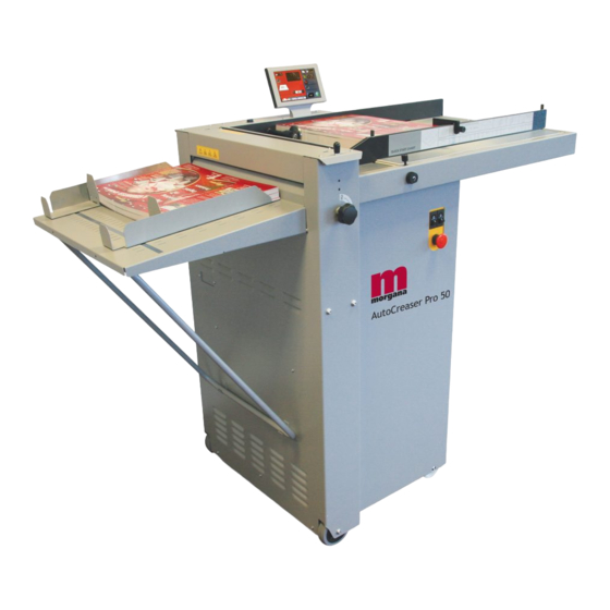
- Page 6 AUTOCREASER 50 AutoCreaser 50 DOCUMENT CREASING MACHINE Key to photograph below Roller tilt handle Adjustable side lay Control Panel Stacker assembly Back Stop Fuses Suction slot knob Fixed side lay Gap Set Knob and Lever The display unit Roller tilt knob...
-
Page 7: The Controls The Control Panel
AutoCreaser 50 THE CONTROLS The Display Unit and the Switches on the Control Panel allow the operator to read, edit, create and initiate numerous creasing programs within the memory. The Control Panel houses the Selection Switch, Compressor switch, System switch, and an industry standard Emergency Stop switch which will stop all power going to the machine when activated. -
Page 8: Features On The Control Panel
THE CONTROLS Features on the Control Panel Selection Switch Allows the operator to scroll through stored addresses and programs, increase or decrease the batch quantity and set a crease position. System switch When activated the system switch will operate the motors in order to begin the creasing sequence. -
Page 9: Quick Start Guide
AutoCreaser 50 Quick Start Guide Setting the machine to operate in automatic mode Set the gap between the paper gate and the vacuum roller to approximately twice the thickness of the stock to be creased. Place the stock to be creased onto the loading table against the fixed side lay. - Page 10 Quick Start Guide Following the arrows on the display unit; move the selection switch to the right to select Setup (i.e. Setting the crease positions), a typical display is shown below. Set Creases More Home 1st Crease 148.0 2nd Crease Following the arrows on the display unit;...
- Page 11 AutoCreaser 50 Quick Start Guide 11. When the required creases have been set, move the selection switch up step by step until the display contains the word Feed , see below. Setup Tools Feed Zero Batch Off Total 2 Creases Program 3 12.
-
Page 12: Operating The Autocreaser
Operating the Autocreaser 50 Setting the Machine Adjusting the Paper Gate The standard setting for horizontal adjustment of the paper gate is 6.5mm (1/4") away from the mounting block. Turn disc J to make this adjustment. This setting is only intended as a guide, for instance, sheets with an upward curl will require this setting to be in- creased. - Page 13 AutoCreaser 50 Operating the Autocreaser 50 Setting the Vacuum Bleed Situated on the front of the feed table, the Vacuum Bleed Knob is used to allow more control of the suction on the vacuum drum. When light weight paper of 90gsm and lower is being fed through the machine turn the knob...
- Page 14 Operating the Autocreaser 50 To operate the motors manually, switch the machine ‘on’ at the Emergency Stop switch. Following the arrows on the display unit, move the selection switch to the left to select Tools, the display will now show the Tools sub-menu. Press the system switch down and then move the selection switch to the left or to the right, to rotate the rollers in short pulses.
- Page 15 AutoCreaser 50 Operating the Autocreaser 50 Setting the infeed roller gap set The gap between the infeed rollers must be adjusted to suit the stock being used. The gap set can be adjusted as follows:- 1. Place a sample sheet of the stock to be used onto the feed bed.
-
Page 16: Programming The Machine
Operating the Autocreaser 50 Programming the machine Switch the power ‘on’ by turning the Emergency stop button clockwise to release the safety latch. The display is now switched on. Setting the batch quantity and Dwell Time (i) Move the selection switch to the right to select... -
Page 17: Paper Jamming
AutoCreaser 50 Operating the Autocreaser 50 (v) Move the selection switch to the right to select Select (vi) Move the selection switch to the left to select or to the right to select Running the machine 5. To run the job with the selected settings. - Page 18 The Stacker Assembly The stacker unit on the Autocreaser 50 is used to catch the sheets once they have been creased or perforated. Setting the Stacker assembly Assemble the stacker unit to the machine as shown in fig 13.1 below.
- Page 19 AutoCreaser 50 The Stacker Assembly Whilst the sheet is between the two guides on the stacker bed, set the distance between the top of the sheet and the backstop flanges to approximately 5mm. For shorter sheets, the back stop can be used (as shown in FIG 13.1 to adjust the position of the paper stack.
- Page 20 Perforating Once the machine is set-up, the Autocreaser 50 can be used to perforate or crease. Note Perforating and creasing can be carried out simultaneously. However, if any adjustment is made to the roller tilt mechanism in order to compensate for the perforation line being ’out of square’, this may effect the accuracy of the crease.
-
Page 21: Setting The Machine
AutoCreaser 50 Perforating All of the blades and anvils are supplied with fixings. *Perforator stripper Standard Part Number 78-013 *It is recommended that for multiple perforations, a separate perforator stripper is used for every perforating blade set fitted in the creasing unit. - Page 22 Perforating 11. Mount the other anvil ensuring that they have matched on the drive hub. Secure the anvil to the hub ensuring not to over tighten grub screw as shown in fig 16.2. 12. Slide the drive hub towards the perforating drive wheel until there is a clearance of 0.5mm.
- Page 23 AutoCreaser 50 The Blade Assembly Adjusting the blade pressure (no paper required) 1. (i) Switch the power ‘on’ by turning the Emergency stop button clockwise to release the safety latch. The display is now switched on and will show the start up menu as shown below.
- Page 24 The Blade Assembly Adjusting the blade alignment It is extremely important that the blade and anvil assembly within the creasing unit is correctly aligned. Misalignment of the blade or anvil can lead to damaged profiles and subsequently poor quality creasing so it must, therefore, be corrected immediately. If the blade set is misaligned, the media being driven will be subject to scoring or even tearing at any point along the crease line.
- Page 25 AutoCreaser 50 Replacing Blade Set Before removing the blade assembly, ensure that the lower blade / anvil is NOT at ‘top dead centre’, Switch the machine off. Remove the stacker unit and lift the exit guard. Blade Extractor Tools Using a 6mm allen key, loosen the socket head screws located inside the blade adjustment cams.
-
Page 26: Spares
Replacing Blade Set FIG 21.1 11. Push the exit guard down and replace the stacker assembly before operating the machine. 12. Switch the machine on and test the crease for form. If the pressure and the alignment of the crease is not to a satisfactory level, see pages 23 –25 to adjust the creasing line. -
Page 27: Trouble Shooting
Check that the clearance between the paper gate and the suction roller is not set too low. • On digital media, the feeding performance may be improved if the leading edge of the stack is trimmed before loading onto the Autocreaser 50. SYSTEM Page 27... - Page 28 Trouble Shooting • Check that the air distribution has been correctly set. • Check that the air separation has been set high enough to feed the sheets. • For heavy stocks, very small or very large sheets, embossed or even irregular stock, it may be required to feed the sheets manually - see page 17 for instructions.
- Page 29 With the blade assembly removed, clean the slots and surrounding area within the creasing unit. Technician Maintenance It is recommended that your Morgana Autocreaser 50 is fully serviced at least once every six months by a factory trained Service Engineer. SYSTEM...
-
Page 30: Dispatch Kit
7-95-10 DISPATCH KIT ITEM PART NUMBER DESCRIPTION OPERATORS MANUAL - AUTOCREASER 50 70-069 90-018 ROLLER CLEANING KIT 650-040 POWER CORD CE UK C19 3Pin 16A 2.5Mtrs. 617-004 GLASS BALL - Ø20 SCREW - SOCKET CAP HEAD - M3 x 6 LG... -
Page 31: Accessories & Options
PERFORATING BLADE SET 28T (Single sheets) 1-99-41 PERFORATING BLADE SET 56T (Fine perforations) 1-99-35 ANVIL SET USED WITH ABOVE BLADE SETS 76-237-03 BLADE SET - NARROW - AUTOCREASER 50 70-082 ANTI-STATIC KIT - AUTOCREASER 50 94-073-03 SIDELAY EXTENSION - NARROW SHEET - A/C 50 ACCESSORIES.. -
Page 32: Recommended Spares
609-022 ‘O’ RING Ø32 606-035 KNOB - Roller Tilt 76-109 POWER LINK BEARING 76-237-02 BLADE SET - Standard - Autocreaser 50 76-042 DRIVE BELT - FEED BED 607-042 TIMING BELT 160XL 607-048 TIMING BELT TWIN GRIP - 200 DXL 050... - Page 33 AutoCreaser 50 RECOMMENDED SPARES PART NUMBER DESCRIPTION 76-203-05 INPUT ROLLER - Upper - Autocreaser 50 76-203-06 INPUT ROLLER - Lower - Autocreaser 50 76-019-02 OUTPUT SHAFT - Wide 78-013 PERFORATOR STRIPPER ASSEMBLY 613-351 MICRO SWITCH - Guard Circuit 613-191 MICRO SWITCH - Home Circuit...
- Page 34 PRODUCT RECYCLING & DISPOSAL European Union Disposal Information for Commercial Users Application of this symbol on your equipment is confirmation that you must dispose of this equipment in compliance with agreed national Procedures. In accordance with European legislation end of life electrical and electronic equipment subject to disposal must be managed within agreed procedures.
- Page 35 AutoCreaser 50 SYSTEM Page 35...
Need help?
Do you have a question about the AutoCreaser 50 and is the answer not in the manual?
Questions and answers