Table of Contents

Related Manuals for Wincomm WMP-19B


Summary of Contents for Wincomm WMP-19B
- Page 1 WMP-19B/22B Medical Panel PC USER’S MANUAL V1.0 Copyright© ,2016. All rights reserved All other brand names are registered trademarks of their respective owners. The information contained in this document is subject to change without notice...
- Page 2 Version Change History Date Version Description Remark 2016/5/31 First release James WMP-19B/22B User’s manual...
- Page 3 Intel is a trademark or registered trademark of Intel Corporation. Microsoft Windows is a registered trademark of Microsoft Corporation. Winbond is a registered trademark of Winbond Electronics Corporation. All other product names or trademarks are properties of their respective owners. WMP-19B/22B User’s manual...
- Page 4 To avoid risk of electric shock, this equipment must only be connected to a supply mains with protective earth. Do not modify this equipment without authorization of the manufacturer. WMP-19B/22B User’s manual...
-
Page 5: Safety Instructions
Safety Instructions Intended use The WMP-19B/22B is intended to serve as a medical monitor which is designed for general purpose for hospital environment. It shall not be used for life-supporting system. Intended User profile The equipment is intended for infant or adults by profession Health care professionals. - Page 6 If your hands are wet, do not touch the plug. Use your thumb and index finger, grip firmly on the power cord to disconnect from the electrical socket. By pulling the power cord, may result in damaging it. WMP-19B/22B User’s manual...
- Page 7 Unless proper ventilation is present, do not place unit in an enclosed area; such as a built-in shelf. Keep a minimum distance of 10 cm between the display unit and wall. WMP-19B/22B User’s manual...
- Page 8 AC outlet. 2. Turn on the computer. Servicing, Repairing, Maintenance & Safety Checks If the unit is not functioning properly, observe the performance level of the display closely to determine what type of servicing is needed. viii WMP-19B/22B User’s manual...
- Page 9 If unauthorized parts are used it may result in starting a fire, electrical shock and/or other dangers. ISO 7000-0434: Caution. ISO 7000-1641: Follow operating instructions or Consult instructions for use. IEC 60417 -5009: STAND-BY. IEC 60417-5031: Direct current. WMP-19B/22B User’s manual...
- Page 10 The mark on electrical and electronic products only applies to the current European Union Member States. WMP-19B/22B User’s manual...
- Page 11 IEC 60601-1-1. The unit is for exclusive interconnection with IEC 60601-1 certified equipment in the patient environment and IEC 60XXX certified equipment outside of the patient environment. If in doubt, consult the technical services department or your local representative. WMP-19B/22B User’s manual...
-
Page 12: Contact Information
C) Caution: This adapter Sinpro HPU180A-108 is a forming part of the medical device Contact information: Wincomm Corporation 3F, No.14, Prosperity Road II, Science-Based Industrial Park, Hsinchu, Taiwan 300, R.O.C TEL: (886) 3 5780000 E-Mail: Sales@wincomm.com.tw WMP-19B/22B User’s manual... -
Page 13: Table Of Contents
Appendix ..........31 A. Jumper settings and Connectors ....31 B. Battery Pack Specifications (optional kit) .. 50 C. How to disable battery when system hang up -WMP-19B/22B ......... 51 D. Scrap Computer Recycling ...... 52 xiii WMP-19B/22B User’s manual... -
Page 15: Introduction
WMP-22B has a 250nits 21.5” TFT display with 1920 x 1080 resolutions. WMP-19B has a 19” 350nits TFT display with 1280 x 1024 resolutions. Integrating with high brightness LCD is easier to analyze DICOM image. -
Page 16: Package List
Package list Before you begin installing your Medical Station, please make sure that the following items have been shipped: The WMP-19B/22B Medical Panel PC unit User's manual, chipset drivers Power Adapter x 1 (Mf:Sinpro, type/model: HPU180A-108) Power cord – Hospital grade used (US type), or other type in UK, EU…etc. -
Page 17: Features
Supports PCI-E x16 riser card (option) Easy clean full flat 5 wire resistive touch screen (customized order configuration) USB/LAN/COM isolated module by different configuration (optional order configuration) Optional 28W battery pack, desktop stand DICOM Compliance (project customized) WMP-19B/22B User’s manual... -
Page 18: Specifications
DC-in w/ lock function *1 Gigabit LAN RJ-45 Connectors *2 DP output *2 Sound: Line-in *1 Line-out *1 2W Speaker *2 (WMP-19B) / 1.5W Speaker *2 (WMP-22B) Isolated version Isolated 4KV USB2.0 *1 Isolated 4KV GigaLAN *1 Isolated 4KV RS-232 *1, RS-232/422/485 *1... - Page 19 Construction 3mm ABS + PC TYPE Plastic housing WMP-22B: 540 x 375 x 78 mm Dimension (WxHxD) WMP-19B: 450 x 420 x 85.3 mm WMP-22B: 8.0 kg (w/o power adapter) Net Weight WMP-19B: 7.5 kg (w/o power adapter) Packing Filler...
- Page 20 100M times Configuration 2 - 5 wire Resistive touch Type Full flat 5-wire, Analog Resistive Interface USB interface, 5V Resolution 4096 x 4096 Light Transmission >78% at 550 nm wavelength Life Time 35M times, 250g at same place WMP-19B/22B User’s manual...
-
Page 21: Guidance And Manufacturer's Declaration - Electromagnetic Emissions
Guidance and manufacturer’s declaration – electromagnetic emissions The model WMP-19B/22B is intended for use in the electromagnetic environment specified below. The customer or the user of the model WMP-19B/22B should assure that it is used in such an environment. Electromagnetic environment – Emissions test Compliance... -
Page 22: Guidance And Manufacturer's Declaration - Electromagnetic Immunity
Guidance and manufacturer’s declaration – electromagnetic immunity The model WMP-19B/22B is intended for use in the electromagnetic environment specified below. The customer or the user of the model WMP-19B/22B should assure that it is used in such an environment. Immunity test IEC 60601 Compliance Electromagnetic environment –... -
Page 23: Immunity
Guidance and manufacturer’s declaration – electromagnetic immunity The model WMP-19B/22B is intended for use in the electromagnetic environment specified below. The customer or the user of the model WMP-19B/22B should assure that it is used in such an environment. Immunity Electromagnetic environment –... - Page 24 If the measured field strength in the location in which the model WMP-19B/22B is used exceeds the applicable RF compliance level above, the model WMP-19B/22B should be observed to verify normal operation. If abnormal performance is observed, additional measures may be necessary, such as reorienting or relocating the model WMP-19B/22B.
-
Page 25: Cleaning/Disinfecting
Cleaning/Disinfecting Steps: 1. Wipe the WMP-19B/22B with a dry clean cloth. 2. Operate with manufacturer’s instructions or hospital protocol. Cautions: Do not immerse or rinse the WMP-19B/22B and its peripherals. If you accidentally spill liquid on the device, disconnect the unit from the power source. -
Page 26: Getting Started
“F11” key, go into BIOS quick boot menu, select “USB-CD ROM”, WAIT FOR 20 SECONDS, then press enter, system OS will boot up from USB-CD/DVD drive directly. Notice: The installation is only to be carried out by manufacturer trained and authorized personnel. WMP-19B/22B User’s manual... -
Page 27: Dimension
Dimension WMP-22B (VESA Mount Screw type: M4) WMP-19B/22B User’s manual... - Page 28 WMP-19B (VESA Mount Screw type: M4) WMP-19B/22B User’s manual...
-
Page 29: System View
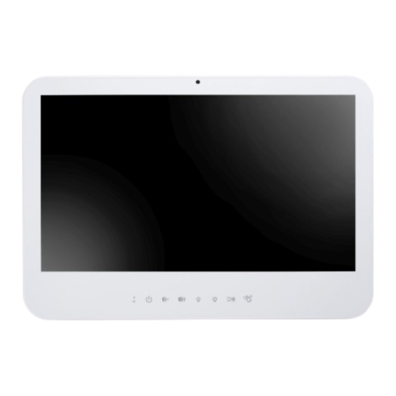
Battery low: Yellow blinking 2. Power (with LED status indicator: ON: Green, OFF: dark) 3. Volume adjustment (-) 4. Volume adjustment (+) 5. Brightness (-) 6. Brightness (+) 7. LCD on/off (with LED status indicator: LCD ON: dark, LCD OFF: WMP-19B/22B User’s manual... - Page 30 Keep on contacting 5 seconds to active b. keep contacting 5 seconds to release c. auto release after 60 seconds d. keep on contacting below for 5 seconds to toggle DICOM mode enabled/disable if DICOM module presents I/O parts (WMP-19B/22B) WMP-19B/22B User’s manual...
- Page 31 Isolated I/O parts (WMP-19B/22B) WMP-19B/22B User’s manual...
-
Page 32: Disconnect Device
Unplug the power cord from the power adapter jack to disconnect the device. Turn off the system: Turning off WMP-19B/22B properly is important for system reliability. 1. On the start menu, click “Shut down” and select “OK” WMP-19B/22B User’s manual... -
Page 33: Bios Setup
<PgUp> and <PgDn> keys to change entries, <F1> for help and <Esc> to quit. When you enter the Setup utility, the Main Menu screen will appear on the screen. The Main Menu allows you to select from various setup functions and exit choices. WMP-19B/22B User’s manual... - Page 34 This section provides information on the BIOS information, and Battery information System Date Set the system date. Use the <Tab> key to switch between data elements. System Time Set the system time. Use the <Tab> key to switch between time elements. WMP-19B/22B User’s manual...
- Page 35 Sleep State). This option may be not effective with some OS. ACPI Sleep State Select the highest ACPI sleep state the system will enter when the SISPEND button is pressed. F81216 Super IO Configuration Serial Port 1 Configuration Serial Port Enable or Disable Serial Port (COM). Function WMP-19B/22B User’s manual...
- Page 36 Serial Port 6 Configuration Serial Port Enable or Disable Serial Port (COM). Change Settings Select an optimal settings for super IO Device. Intel(R) Smart Connect Technology ISCT Support Enable/Disable Intel Smart Connect S5 RTC Wake Settings Wake system From S5 WMP-19B/22B User’s manual...
-
Page 37: Ide Configuration
Enable / Disable Serial ATA Port 1. SATA Port0 HotPlug Enable / Disable SATA Port1 HotPlug Embedded Controller Configuration Lock key click time Number of seconds to press lock key to (un)active. 1~10 seconds mean press hold time. Locked Status Hold Time WMP-19B/22B User’s manual... - Page 38 Enable / Disable PCIE Dynamic Clock Gating. Show/hide hidden items For debug only. Show / hide hidden items. Info Report Configuration Post Report Post Repost Support Enabled / Disabled. Info Error Message Info Error Message Support Enabled / Disabled. WMP-19B/22B User’s manual...
-
Page 39: Usb Configuration
USB devices are connected. DISABLE option will keep USB devices available only for EFI applications XHCI Hand-off Enable / Disable XHCI Controller Legacy support. USB Mass Storage Driver Support Enable/Disable USB Mass Storage Driver Support. WMP-19B/22B User’s manual... -
Page 40: Audio Controller
Disabled = Azalia will be unconditionally disabled. Enable = Azalia will be unconditionally Enabled. Auto = Azalia will be enabled if present disabled otherwise. Restore AC Power Loss Select AC power state when power is re-applied after a power failure. WMP-19B/22B User’s manual... - Page 41 Security Administrator Password Set Administrator Password. User Password Set user Password. P0:TOSHIBA MQ01 HDD Security Configuration for selected drive. WMP-19B/22B User’s manual...
- Page 42 Selects the keyboard NumLock state. PXE Boot PXE Network Boot Enable / Disable. OS Selection OS Selection. Quiet Boot Enable or disables Quiet Boot option. Boot Option #1 Sets the system boot order. Boot Option #2 Sets the system boot order. WMP-19B/22B User’s manual...
- Page 43 Reset system setup without saving the changes. Save Changes Save the changes done so far to any of setup options. Discard Changes Discard the changes done so far to any of setup options. Restore Defaults Restore/load default values for all the setup options. WMP-19B/22B User’s manual...
- Page 44 Launch EFI Shell From filesystem device Attempts to Launch EFI Shell application (Shell.efi) from one of the available filesystem devices. Reset System with ME disable ModeMEUD000 ME will runs into the temporary disable mode, Ignore if ME Ignition FWMEUD001. WMP-19B/22B User’s manual...
-
Page 45: Appendix
A. Jumper settings and Connectors This appendix gives the definitions and shows the positions of jumpers, headers and connectors. All of the configuration jumpers on WMP-19B/22B are in the proper position. Note: Some of jumpers or connectors will be removed base on system configuration. - Page 46 JP2 – Touch Panel Type Selection Description Jumper Setting X+/UL_R 1-2 (default) Y+/UR_R 3-4 (default) X+/UL_R Y+/UR_R SWITCH_4_5W 9-10 JP3 – Panel Resolution Settings GPIO0 GPIO1 GPIO2 GPIO3 Description Jumper Setting 1024X768(6bit) 1024X768(8bit) 1280X800(8bit) 1280X1024(8bit) 1920X1080(8bit) GPIO0 Low (default) WMP-19B/22B User’s manual...
- Page 47 Jumper Setting Normal Open 1-2 (default) CMOS Clear JP7 – mSATA setting Description Jumper Setting mSATA_SEL43 mSATA_SEL51 JP8 – SATA or SATA DOM Selection Description Jumper Setting SATA DOM 1-2 ---power +5V SATA Port 2-3(default)--- GND WMP-19B/22B User’s manual...
- Page 48 PJ1 /PJ2 – HDD Power Connector Pin # Signal Description +12VS Ground Ground +5VS PJ3 – Battery Connector Pin # Signal Description BATT+ BATT+ BATT+ BATT_T BATT_CLK BATT_DAT BATT_EN# Ground Ground Ground PJ4 – Power Jack Connector WMP-19B/22B User’s manual...
- Page 49 Symbol Symbol Symbol Symbol Symbol Symbol VREFDQ DQ27 DQS4 DQ31 DQ38 CKE0 DQ34 DQ39 DQ35 DQS0# DQ44 DQ40 DQS0 NF/A14 DQ45 DQ41 DQS5# DQS5 DQ42 DQ12 DQ46 DQ43 DQ13 DQ47 DQS1# DQ48 DQ52 DQS1 DQ49 RESET# DQ53 WMP-19B/22B User’s manual...
- Page 50 +LCD (+5V/ +3.3V) +LCD (+5V/ +3.3V) +LCD (+5V/ +3.3V) Ground Ground Ground Ground A_RxIn0- B_RxIn0- A_RxIn0+ B_RxIn0+ Ground Ground A_RxIn1- B_RxIn1- A_RxIn1+ B_RxIn1+ Ground Ground A_RxIn2- B_RxIn2- A_RxIn2+ B_RxIn2+ Ground Ground A_CKIN- B_CKIN- A_CKIN+ B_CKIN+ Ground Ground WMP-19B/22B User’s manual...
- Page 51 J5 – Res Touch Panel Interface Signal Description Pin # 8-wire 4-wire 5-wire UL(X+) UL(X+) UL(X+) UR(Y+) UR(Y+) UR(Y+) PROBE LR(X-) LR(X-) LR(X-) LL(Y-) LL(Y-) LL(Y-) X+_DRIVE Y+_DRIVE X-_DRIVE Y-_DRIVE J6 / J12 – Mini PCI Express Socket WMP-19B/22B User’s manual...
- Page 52 +3.3VSB PERp0 +1.5VS SMB_CLK PETn0 SMB_DATA PETp0 USB_D- USB_D+ +3.3VSB +3.3VSB Reserved Reserved CL_CLK Reserved CL_ DATA +1.5VS Controller Link RST# Reserved +3.3VSB J7 – BIOS Socket Pin # Signal Description Pin # Signal Description SCLK HOLD# WMP-19B/22B User’s manual...
- Page 53 Pin # Signal Description +5VSB +5VSB Data - Data + Ground Ground J9/J14/J15 – Internal USB 2.0 Pin Header (co-layout) Pin1 Pin # Signal Description +5VSB +5VSB Data - Data + Ground Ground J16– Power / HDD LED WMP-19B/22B User’s manual...
- Page 54 RDY# J18 –TPM / ID-394 Pin # Signal Description Pin # Signal Description LPC AD0 PLT reset# LPC AD1 SERIRQ LPC AD2 +3.3VS LPC AD3 +5VSB LPC Frame# CLKRUN# Debug CLK SMB CLK SMB DATA SUS_STAT# +3.3VSB WMP-19B/22B User’s manual...
- Page 55 APPENDIX J19 / J21 – Standard SATA Interface Pin # Signal Description Ground Ground Ground J23 – PS2 KB/MS Pin # Signal Description KBDATA MSDATA Ground +5VSB KBCLK MSCLK WMP-19B/22B User’s manual...
- Page 56 J24 – EC Reset Pin # Signal Description EC_RESET# J25 – Battery Socket Pin # Signal Description RTC +3.3V J27 – GPIO Connect Pin # Signal Description Pin # Signal Description GEN_GPO1 GEN_GPI1 GEN_GPO2 GEN_GPI2 GEN_GPO3 GEN_GPI3 GEN_GPO4 GEN_GPI4 WMP-19B/22B User’s manual...
- Page 57 APPENDIX J28 –CAP Front Bezel Button Light Sensor Connect Pin # Signal Description +5VSB +3.3VSB KP_SCL KP_SDA PWR_LED# KP_P_LED SATA_LED# J29 –Light Sensor Connect Pin # Signal Description +5VSB +3.3VSB KP_SCL KP_SDA PWR_LED# KP_P_LED SATA_LED# WMP-19B/22B User’s manual...
- Page 58 232_DCD# 232_DSR# 232_SIN 232_RTS# 232_SOUT 232_CTS# 232_DTR# 232_RI# +5VS / +12VS J31 – Internal COM4 TTL Pin # Signal Description Pin # Signal Description DCD# DSR# RTS# SOUT CTS# DTR# +5VS J32 – External USB 3.0 Port WMP-19B/22B User’s manual...
- Page 59 J33, J42 – RIGHT / LEFT CH for Speaker Signal Description Pin # J33 (RIGHT CH) J42 (LEFT CH) ROUT+ LOUT+ ROUT- LOUT- J34 –External RJ45 Ethernet Port Pin # Signal Description Data0+ Data0- Data1+ Data2+ Data2- Data1- Data3+ Data3- WMP-19B/22B User’s manual...
- Page 60 Pin # Signal Description Power ON J36,J37,J38 – External USB 2.0 Port Pin # Signal Description USB_D- USB_D+ J39 – External DVI-I Connector Pin # Signal Description Pin # Signal Description DVI Data2- DVI Data2+ DVI SCL WMP-19B/22B User’s manual...
- Page 61 J40 / J41 – External Audio Phone Jack Pin # Signal Description Line Out (stereo) Green Microphone (stereo) Pink J43 – Internal COM3 Serial Port Pin # Signal Description Pin # Signal Description 232_DCD# 232_DSR# 232_SIN 232_RTS# 232_SOUT 232_CTS# 232_DTR# 232_RI# +5VS WMP-19B/22B User’s manual...
- Page 62 Pin # Signal Description SYS_RESET# J45 – Reset connector Pin # Signal Description SYS_RESET# J46 – External COM2 Connector Pin # Signal Description Pin # Signal Description 232_DCD 232_SIN 232_SOUT 232_DTR 232_DSR 232_RTS 232_CTS 232_RI Not Used WMP-19B/22B User’s manual...
- Page 63 Transmit Data - Transmit Data - Receive Data Transmit Data + Transmit Data + Transmit Data Receive Data + Data Terminal Ready Receive Data - Ground Data Set Ready Request to Send Clear to Send Ring Indicator WMP-19B/22B User’s manual...
-
Page 64: Battery Pack Specifications (Optional Kit)
Discharge Protection UVP/OCP Charge Protection OVP/OTP Self-discharge Rate 10uA ~800 uA Dimensions 133 x 47 x 21mm Weight 240g max. Ambient Temperature 0°C ~ +40°C Storage Temperature -20°C ~ +60°C Energy 28.08Wh Backup 53 W/ 40 min WMP-19B/22B User’s manual... -
Page 65: How To Disable Battery When System Hang Up -Wmp-19B/22B
2. Remove AC power cord, then the battery LED will on. 3. Press volume up key 10 seconds, then all LED will turn on and turn off 4. Plug in AC power cord again, press power button then you can power on system. WMP-19B/22B User’s manual... -
Page 66: Scrap Computer Recycling
For the computers that are no longer useful or work well, please contact with worldwide distributors for recycling. The worldwide distributors show on the following website: http://www.wincomm.com.tw/contact.aspx Note: Follow the national requirement to dispose unit WMP-19B/22B User’s manual...
Need help?
Do you have a question about the WMP-19B and is the answer not in the manual?
Questions and answers