
Related Manuals for Wincomm WTP-8B66 Series


Summary of Contents for Wincomm WTP-8B66 Series
- Page 1 WTP-8B66 Series User’s Manual 205G00WTP8B660 P/N: , Version V1.4 Copyright 2016, ALL RIGHTS RESERVED. All other brand names are registered trademarks of their respective owner...
- Page 2 Copyright Notice Copyright © 2015 All Rights Reserved. Printed in Taiwan. The information contained in this document is subject to change without any notices. Acknowledgments Greeting & Setup Thank you for purchasing the WTP-8B66 Panel PC. We wish that this unit will be durable and reliable in providing your needs.
- Page 3 tangled with the unit. Do not overload the AC outlets or extension cords. Electrical shocks or fires may occur from overloading. Do not touch the power source during a thunderstorm. If your hands are wet, do not touch the plug. Use your thumb and index finger, grip firmly on the power cord to disconnect from the electrical socket.
- Page 4 A liquid was spilled on the unit or objects have fallen into the unit. The unit is soaked with liquids. iii. The unit is dropped or damaged. If smoke or strange odor is flowing out of the open frame unit. If the power cord or plug is damaged.
- Page 5 The specification is subject to change without notice. Version Change History Date Version Description Remark 2014/12/29 V1.0 First release 2015/04/15 V1.1 Update touch stylus 2015/07/15 V1.2 Remove reset button information Ivy 2015/12/01 V1.3 Add wall mount and table stand assemble information V1.4 2016/05/24 Eddie...
-
Page 6: Table Of Contents
How to Use This Manual ............ 2 System Overview ............. 2 System View ..............15 Setting up the System............17 Installing System Software ..........17 Installing the Drivers............18 BIOS Setup Information ......... 20 Appendix .............. 28 Jumper settings and Connectors ..28 Connector Definition ............ -
Page 7: How To Use This Manual
How to Use This Manual This manual is written for the system integrator, PC technician and knowledgeable PC end user. It describes how to configure your WTP-8B66 Panel PC to meet various operating requirements. The user’s manual is divided into three chapters, with each chapter addressing a basic concept and operation of the server board. -
Page 8: Internal Rs232 X
Internal RS232 x 1 RS232 (Jumper 5V, 12V) x1 External USB 2.0 type a x 4 Internal Mini-PCIE x 2(default) or USB 2.0 pinhead x 2(option) Touch x 1 Pin head X 2 Generates system reset; 256 segments, 0, 1, 2…25 BIOS Brand: AMI Flash ROM size: 64MB... - Page 9 Active Area (mm) 304.128 (W) x 228.096 (V) Outline Dimensions (mm) 326.5 (H) × 253.5 (V) × 11.8 Pixel Pitch (mm) 0.297 Mode Number of Colors 16.7M View Angle (H/V) 160/160 Brightness (cd/m2) Contrast Ratio 600:1 Response Time (ms) (at 25°C) Backlight Weight (g)
- Page 10 1 x M12 8pin for COM 1/RS-232/422/485 (Default RS-232) 1 x M12 8pin for COM 2/RS-232 RS-232: TxD, RxD, RTS, CTS, DTR, DSR, DCD, GND 1 x M12 8pin for LAN 1 Power 1 x M12 5pin DC power connector Power Power DC-In connector x 1...
- Page 11 anti UV and 7H coating full flat PCT touch screen IP69K 1000 nit high brightness LCD LCD Auto dimming LCD Super dimming (low brightness) Packing list 1. WTP-8B66-15 2. DVD-Title for driver and manual 3. Power adapter 4. Power cord Regulatory FCC, CE (EMC), VCCI class B Shock/Vibration/Drop...
- Page 12 WTP-8B66-19 System Intel® Celeron® J1900 2.0 GHz quad-core processor 10W Graphic Intel® HD Graphics Audio Realtek ALC262 Audio Codec, 2+2 watts power amplifier Intel I210-AT Gigabit Ethernet x 2 Memory Dual Channel, two DDR3 SODIMM socket support up to 8GB DDR3L-1333 Serial ATA SATA II controller (3.0Gb/sec) Port x 2...
- Page 13 Display Brand Resolution (pixel) SXGA 1280(x3) x 1024 Active Area (mm) 376.32 (H) x 301.06(V) Number of Colors 16.7M View Angle (H/V) 170 / 160 Brightness (cd/m2) Contrast Ratio 1000:1 Response Time (ms) (at 25°C) Backlight Weight (g) 1670 life time<Hrs> 50000 Touch Screen Type...
- Page 14 Hardness Glass thickness 2.4mm 1.5%, Y 1.5% Linearity ≦ ≦ Active area 308.11x232.09mm Resolution 4096x4096 Lifetime 36 million activations Storage 2.5” SATA drive bay x 1 Expansion slots Mini-PCIe External water/dust resistant I/O (rear side) 1 x M12 8pin for USB 1/2 1 x M12 8pin for USB 3/4 1 x M12 8pin for COM 1/RS-232 1 x M12 8pin for COM 2/RS-232...
- Page 15 Mounting VESA (100x100 mmxmm) side mount (M6*2) Supported OS Win 7, Win 7 Pro, Win8.1 Options Wireless or Wireless and BT kit (2 ant) Waterproof COM cable, cable length is 2 meters Waterproof USB cable, cable length is 2 meters Waterproof LAN cable, cable length is 2 meters wall mount / table mount bracket (option) Intel Core i7-3517U (option) turbo mode disable...
- Page 16 Shock Vibration Drop Operating: Operating: According to ISTA Project 2A Pulse shape 5 ~ 500Hz , to determine a drop height in : Acceleration Half-sine the following chart. : waveform 1.0G (test surface: concrete, Sweep time Impact with packing)6 surfaces :...
- Page 17 Step 2. Please follow the picture diagrams to assemble. Explode View Step 3. Please tighten the black handle in a clockwise direction.
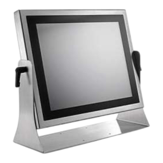
- Page 18 Wall Mount Stand Assemble Instruction...
- Page 19 Step 1. Please check out the following parts before assemble. Item Quantity Wall Mount Stand Black Silicone Washer Black Handle Step 2. Please follow the picture diagrams to assemble. Explode View Step 3. Please tighten the black handle in a clockwise direction.
-
Page 20: System View
System View... - Page 21 WTP-8B66-15 Outline Drawing...
-
Page 22: Setting Up The System
WTP-8B66-19 Outline Drawing Setting up the System The following is a summary of the steps in setting up the system for use. CAUTION: Make sure that power to the system and each of the devices to be connected is switched OFF before plugging in the connectors. -
Page 23: Installing The Drivers
You can use the Ethernet port to download software from the net to the HDD that has been pre-installed in WTP-8B66 Panel PC Method 2: Use the COM Port WTP-8B66 By connecting another PC to the Panel PC with an appropriate cable, you can use transmission WTP-8B66 software to transmit Operation System Software to the HDD that has been pre-installed in the Panel PC. -
Page 24: Wtp-8B66
5. Reboot system Step 4 – Install Audio Driver 1. Open fie of LAN 2. Click on the setup.exe 3. Follow the instructions that the window shows 4. The system will help you install the driver automatically 5. Reboot system... -
Page 25: Bios Setup Information
BIOS Setup Information BIOS Introduction The AMI BIOS (Basic Input / Output System) installed in your computer system’s ROM supports Intel processors. The BIOS provides critical low-level support for a standard device such as disk drives, serial ports and parallel ports. It also adds virus and password protection as well as special support for detailed fine-tuning of the chipset controlling the entire system. - Page 26 Advanced Launch OpROM Support Launch PXE OpROM Enables or disables Boot Option for Legacy Network Devices. Launch Storage OpROM Enables or disables Boot Option for Legacy Mass Storage Devices with Option ROM. PCI Subsystem Settings PCI ROM Priority In Case of multiple Option ROMs (Legacy and EFI Compatible), specifies what PCI Option ROM to launch. PCI Latency Timer Value to be programmed into PCI Latency Timer Register.
- Page 27 Set the ASPM Level: Force L0 – Force all links to L0 State : AUTO – BIOS auto configure : DISABLE – Disables ASPM. Extended Synch If ENABLED allows generation of Extended Synchronization patterns. ACPI Settings Enables ACPI Auto Conf Enables or Disables BIOS ACPI Auto Configuration.
- Page 28 Selects DVMT/FIXED Mode Memory size used by Internal Graphics Device. IGD – Boot Type Select the Video Device which will be activated during POST. This has no effect if external graphics present. LCD Panel Type Select LCD panel used by Internal Graphics Device by selecting the appropriate setup item. Panel Scaling Select the LCD panel scaling option used by the Internal Graphics Device.
- Page 29 Set Parameters of Serial Port 1 (COM C). Serial Port 2 Configuration Set Parameters of Serial Port 2 (COM D). Serial Port 3 Configuration Set Parameters of Serial Port 3 (COM E). Serial Port 4 Configuration Set Parameters of Serial Port 4 (COM F). Serial Port Console Redirection Serial Port Console Redirection.
- Page 30 Boot Setup Prompt Timeout Number of seconds to wait for setup activation key. 65535(0xFFFF) means indefinite waiting. Bootup Numlock State Selects the keyboard NumLock state. Quiet Boot Allows you to determine whether to display the AMI Logo at system startup. Disabled displays normal POST message.
- Page 31 Enables or disables the security chip. It is recommended that you use this function with the Administrator/User password.
- Page 32 Save & Exit Save Changes and Exit Exit system setup after saving the changes. Discard Changes and Exit Exit system setup without saving any changes. Save Changes and Reset Reset the system after saving the changes. Discard Changes and Reset Reset system setup without saving the changes.
-
Page 33: Appendix
Appendix A. Jumper settings and Connectors JP5 – Backlight Type Selection Description Jumper Setting 1-2 (for 10”) Analog Inverter 2-3(for 12’’/15”) PWM Inverter... - Page 34 JP6 – Backlight control level Selection Description Jumper Setting +3.3V OPEN (default) JP7 – Touch Panel Type Selection Description Jumper Setting 3M type 1-2, 3-4 (default) ELO type 5-6,7-8 JP8 – LVDS Power Selection Description Jumper Setting +3.3VS(for 10”/12”/15”) 5-6, 7-8 (default) +5VS(for 17”/19”)
- Page 35 JP9 – Sensor Selection Description Jumper Setting No Panel Sensor 1-2(default) No MB Sensor Reserved JP10 – CMOS Clear Description Jumper Setting Normal Open 1-2 (default) CMOS Clear JP11 – SATA / SATADOM Selection Description Jumper Setting SATA 2-3(default) SATA...
- Page 36 Description JP13 JP14 No support (default) Open Open Support *Support Wincomm Y cable only. JP15 –Panel Resolution Selection JP15 jumper setting Panel Color Depth Resolution 800x600 6bit 1024x768 6bit 1024x768 8bit 1280x768 6bit 1280x800 6bit 1280x960 6bit 1280x1024 8bit...
-
Page 37: Connector Definition
Connector Definition PJ5 /PJ6 – HDD Power Connector Pin # Signal Description +12VS +5VS PJ8 – Power Jack Pin # Signal Description DC In DC In PJ9 – Power Input Connector Pin # Signal Description DC In DC In... - Page 38 J5 – LCD Inverter Wafer Header Pin # Signal Description +12VS +12VS Backlight Control Backlight Enable J6, J54, J56 – Internal USB 2.0 Pin Header Pin # Signal Description +5VSB +5VSB Data - Data +...
- Page 39 J9 – LVDS Interface Pin # Signal Description Pin # Signal Description Ground A_TXD3+ B_TXD3+ A_TXD3- B_TXD3- A_CLK+ B_CLK+ A_CLK- B_CLK- A_TXD2+ B_TXD2+ A_TXD2- B_TXD2- A_TXD1+ B_TXD1+ A_TXD1- B_TXD1- A_TXD0+ B_TXD0+ A_TXD0- B_TXD0- +LVDS PWR +LVDS PWR +LVDS PWR +LVDS PWR ...
-
Page 40: Ground
Y+_DRIVE X-_DRIVE Y-_DRIVE J13 / J19 – Mini PCI Express Socket J14 –P-CAP Touch screen interface* Pin # Signal Description +5VSB +5VSB Data - Data + Ground Ground * Res(J10) with P-CAP(J14) select one J15 –TPM / ID-394 Pin # Signal Description Pin #... -
Page 41: Pin # Signal Description Gnd
J16 – For JTAG Pin # Signal Description Pin # Signal Description Reserved Reserved +3.3V Reserved +3.3V +3.3V J17 – Panel Temp Sensor Connector Pin # Signal Description PANEL_SENSOR J21 – BIOS Socket J22 – Battery Socket... - Page 42 J24 – Standard SATA / SATA DOM Interface Pin # Signal Description Ground Ground Ground / +5VS J25 – Standard SATA Interface Pin # Signal Description Ground Ground Ground J26 – PS2 KB/MS Pin # Signal Description KBDATA MSDATA Ground...
-
Page 43: Pin # Signal Description
J27 – MB Heater Connector Pin # Signal Description +12VSB J28 – Power / HDD LED Pin # Signal Description PWR_LED# +3.3VSB +3.3VSB SATA_LED# J29 – Heater Error / Heating LEDs Pin # Signal Description +3.3V HEATER_LED# ERROR_LED# ... -
Page 44: Gnd
ROUT- LOUT- J35 – Internal COM4 Serial Port Pin # Signal Description Pin # Signal Description 232_DSR# 232_DCD# 232_RTS# 232_SIN 232_CTS# 232_SOUT 232_RI# 232_DTR# +5VS J36 – Internal COM3 Serial Port Pin # Signal Description Pin # Signal Description 232_DSR# 232_DCD# 232_RTS#... - Page 45 J39 – GPIO Connect Pin # Signal Description Pin # Signal Description GEN_GPI1 GEN_GPO1 GEN_GPI2 GEN_GPO2 GEN_GPI3 GEN_GPO3 GEN_GPI4 GEN_GPO4 J40 – External USB 3.0 Port J41 / J42 –External RJ45 Ethernet Port Activity/Link LED Status Description No Link Blinking Data Activity...
- Page 46 J44,J45,J46 – External USB 2.0 Port Pin # Signal Description USB_D- USB_D+ J47 – External DVI-I Connector J48 / J49 – External Audio Phone Jack Audio Jack Signal Description Line Out (stereo) Green Microphone (stereo) Pink J50 –...
- Page 47 J52 – External COM1 Connector Signal Description Pin # RS-232 RS-422 RS-485 TX D- DATA- TX D+ DATA+ RX D+ RX D- J53 – External COM2 Connector Pin # Signal Description Pin # Signal Description J54/J55*/J56/J57* – Internal USB 2.0 Pin Header Pin # Signal Description +5VSB...
- Page 48 Pin # Signal Description +5VSB +5VSB Data - Data + *Co-lay with external USB port (J44, J45 and J46). J58 – External PoE Slot (Option) Pin # Signal Description LAN0_MDI0_P LAN0_MDI0_N LAN0_MDI1_P LAN0_MDI1_N LAN0_MDI2_P LAN0_MDI2_N LAN0_MDI3_P LAN0_MDI3_N...
Need help?
Do you have a question about the WTP-8B66 Series and is the answer not in the manual?
Questions and answers