Table of Contents
Advertisement
Quick Links
Download this manual
See also:
User Manual
Advertisement
Table of Contents

Related Manuals for Wincomm WTP-9A66 Series


Summary of Contents for Wincomm WTP-9A66 Series
- Page 1 WTP-9A66 Series User’s Manual 205G00WTP9A660 P/N: , Version V1.3 Copyright © 2014, ALL RIGHTS RESERVED. All other brand names are registered trademarks of their respective owner...
- Page 2 Copyright Notice Copyright © 2014 All Rights Reserved. Printed in Taiwan. The information contained in this document is subject to change without any notices. Acknowledgments Greeting & Setup Thank you for purchasing the WTP-9A66 Panel PC. We wish that this unit will be durable and reliable in providing your needs.
- Page 3 tangled with the unit. Do not overload the AC outlets or extension cords. Electrical shocks or fires may occur from overloading. Do not touch the power source during a thunderstorm. If your hands are wet, do not touch the plug. Use your thumb and index finger, grip firmly on the power cord to disconnect from the electrical socket.
- Page 4 A liquid was spilled on the unit or objects have fallen into the unit. The unit is soaked with liquids. iii. The unit is dropped or damaged. If smoke or strange odor is flowing out of the open frame unit. If the power cord or plug is damaged.
- Page 5 Version Change History Date Version Description Remark 2014/12/29 V1.0 First release 2015/02/04 V1.1 BIOS PXE limitation 2015/07/15 V1.2 Remove reset button information/add 9A66-22 data 2015/11/23 V1.3 Add wall mount and table stand assemble information...
-
Page 6: Table Of Contents
How to Use This Manual ............ 1 System Overview ............. 2 System View ..............17 Setting up the System............19 Installing System Software ..........19 Installing the Drivers............20 BIOS Setup Information ......... 22 Appendix .............. 30 A. Jumper settings and Connectors ....30 Jumper and Connector Definition Block .... -
Page 7: How To Use This Manual
How to Use This Manual This manual is written for the system integrator, PC technician and knowledgeable PC end user. It describes how to configure your WTP-9A66 Panel PC to meet various operating requirements. The user’s manual is divided into three chapters, with each chapter addressing a basic concept and operation of the server board. -
Page 8: System Overview
System Overview WTP-9A66- 15 System FCBGA1023 3rd Generation Intel® Core i7/i5/i3/Celeron® processor (17W max.) Chipset HM65 Graphic Intel® integrated HD Graphics 4000 Audio None Marvell 88E8071 Giga LAN x 2 Memory Two 1066/1333 MHz DDR3 SODIMM socket support dual Channel, non-ECC, up to 16GB SATA SATA 3, 600 MB/s transfer rate x 2, 2 SATA connector for SATA DOM propose. - Page 9 25°C) Backlight Weight (g) 1000 life time<Hrs> 50000 Touch Screen Type 5 wire RES Glove Any type glove Point: Finger or touch pen Input mode Drag: Finger Interface Light Transmission 80±5% Hardness Glass thickness 2.4mm Linearity 1 .5%, Y 1 .5% ≦...
- Page 10 buttons at rear side Power consumption 67.5w(full loading) 2.3w (S3) Mechanical & Environmental Material construction SUS304 stainless steel enclosure, chassis type Fanless cooling Water and dust protection IP66 / NEMA4X Operation Temperature 0~40 (IEC60068-2-2, HDD, air flow cooling) ℃ Storage Temperature -20~60 ℃...
- Page 11 10. Power cord Regulatory FCC, CE (EMC), VCCI class B Shock/Vibration/Drop Shock Vibration Drop Operating: Operating: 3 Feet height free drop 20g, 11ms, 5 ~ 500Hz , still survive, Acceleration 1 .0G Terminal Saw (test surface: concrete, : tooth pluse Non-operating: with packing) Non-operating:...
- Page 12 Generates system reset; 256 segments, 0, 1, 2…255 sec/min. BIOS Brand: AMI Flash ROM size: 32MB Support RTC wakeup /Wake on LAN /Power on after power failure/PnP/ACPI/RTC PS: com port have to be disabled if PXE enable. It is a limitation Display Brand Resolution (pixel)
- Page 13 Expansion slots Mini-PCIe External water/dust resistant I/O (rear side) 1 x M12 8pin for USB 1/2 1 x M12 8pin for USB 3/4 1 x M12 8pin for COM 1/RS-232 1 x M12 8pin for COM 2/RS-232 RS-232: TxD, RxD, RTS, CTS, DTR, DSR, DCD, GND 1 x M12 8pin for LAN 1 Power 1 x M12 5pin DC power connector...
- Page 14 Intel Core i7-3517U (option) turbo mode disable 2 external LAN Customization (by DRF) sunlight readable optical bonding anti UV and 7H coating full flat PCT touch screen IP69K 1000 nit high brightness LCD LCD Auto dimming LCD Super dimming (low brightness) Packing list WTP-9A66-19 DVD-Title for driver and manual...
- Page 15 Chipset HM65 Graphic Intel® integrated HD Graphics 4000 Audio None Marvell 88E8071 Giga LAN x 2 Memory Two 1333/1600 MHz DDR3 SODIMM socket support dual Channel, non-ECC, up to 16GB SATA SATA 3, 600 MB/s transfer rate x 2, 2 SATA connector for SATA DOM propose.
- Page 16 Hardness Glass thickness 2.4mm 1 .5%, Y 1 .5% Linearity ≦ ≦ Active area 480 x271.5mm Lifetime 490,000 hours Storage 2.5” SATA drive bay x 1 Expansion slots Mini-PCIe External water/dust resistant I/O (rear side) 1 x M12 8pin for USB 1/2 1 x M12 8pin for USB 3/4 1 x M12 8pin for COM 1/RS-232 1 x M12 8pin for COM 2/RS-232...
- Page 17 Mounting VESA (100x100 mmxmm) side mount (M6*2) Supported OS Win 7, Win 7 Pro, Win8.1 Options Wireless or Wireless and BT kit (2 ant) Waterproof COM cable, cable length is 2 meters Waterproof USB cable, cable length is 2 meters Waterproof LAN cable, cable length is 2 meters wall mount / table mount bracket (option) Intel Core i7-3517U (option) turbo mode disable...
- Page 18 Operating: Operating: According to ISTA Pulse shape 5 ~ 500Hz , Project 2A to determine : Acceleration Half-sine a drop height in the : waveform 1.0G following chart. Sweep time Impact (test surface: concrete, : acceleration minutes with packing)6 surfaces :...
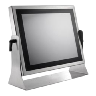
- Page 19 Table Stand Assemble Instruction Step 1. Please check out the following parts before assemble. Item Quantity Table Stand Black Silicone Washer Black Handle Step 2. Please follow the picture diagrams to assemble. Explode View...
- Page 20 Step 3. Please tighten the black handle in a clockwise direction.
- Page 21 Wall Mount Stand Assemble Instruction Step 1. Please check out the following parts before assemble. Item Quantity Wall Mount Stand Black Silicone Washer Black Handle Step 2. Please follow the picture diagrams to assemble. Explode View...
- Page 22 Step 3. Please tighten the black handle in a clockwise direction.
-
Page 23: System View
System View WTP-9A66-15 Outline Drawing... - Page 24 WTP-9A66-19 Outline Drawing...
-
Page 25: Setting Up The System
WTP-9A66-22 outline drawing Setting up the System The following is a summary of the steps in setting up the system for use. CAUTION: Make sure that power to the system and each of the devices to be connected is switched OFF before plugging in the connectors. -
Page 26: Installing The Drivers
NOTE: Some distributors and system integrators may have already pre-installed system software prior to shipment of your Panel PC. Installing software requires an installed HDD. Software can be loaded in the WTP-9A66 Panel PC using any of below methods: Method 1: Use the Ethernet You can use the Ethernet port to download software from the net to the HDD that has been pre-installed in WTP-9A66 Panel PC... - Page 27 6. Reboot system Step 3 – Install Intel® LAN Driver 1. Open fie of LAN 2. Click on the setup.exe 3. Follow the instructions that the window shows 4. The system will help you install the driver automatically 5. Reboot system Step 4 –...
-
Page 28: Bios Setup Information
BIOS Setup Information BIOS Introduction The AMI BIOS (Basic Input / Output System) installed in your computer system’s ROM supports Intel processors. The BIOS provides critical low-level support for a standard device such as disk drives, serial ports and parallel ports. It also adds virus and password protection as well as special support for detailed fine-tuning of the chipset controlling the entire system. - Page 29 Advanced Launch OpROM Support Launch PXE OpROM Enables or disables Boot Option for Legacy Network Devices. Launch Storage OpROM Enables or disables Boot Option for Legacy Mass Storage Devices with Option ROM. PCI Subsystem Settings PCI ROM Priority In Case of multiple Option ROMs (Legacy and EFI Compatible), specifies what PCI Option ROM to launch. PCI Latency Timer Value to be programmed into PCI Latency Timer Register.
- Page 30 Set the ASPM Level: Force L0 – Force all links to L0 State : AUTO – BIOS auto configure : DISABLE – Disables ASPM. Extended Synch If ENABLED allows generation of Extended Synchronization patterns. ACPI Settings Enables ACPI Auto Conf Enables or Disables BIOS ACPI Auto Configuration.
- Page 31 Selects DVMT/FIXED Mode Memory size used by Internal Graphics Device. IGD – Boot Type Select the Video Device which will be activated during POST. This has no effect if external graphics present. LCD Panel Type Select LCD panel used by Internal Graphics Device by selecting the appropriate setup item. Panel Scaling Select the LCD panel scaling option used by the Internal Graphics Device.
- Page 32 Set Parameters of Serial Port 1 (COM C). Serial Port 2 Configuration Set Parameters of Serial Port 2 (COM D). Serial Port 3 Configuration Set Parameters of Serial Port 3 (COM E). Serial Port 4 Configuration Set Parameters of Serial Port 4 (COM F). Serial Port Console Redirection Serial Port Console Redirection.
- Page 33 Boot Setup Prompt Timeout Number of seconds to wait for setup activation key. 65535(0xFFFF) means indefinite waiting. Bootup Numlock State Selects the keyboard NumLock state. Quiet Boot Allows you to determine whether to display the AMI Logo at system startup. Disabled displays normal POST message.
- Page 34 Enables or disables the security chip. It is recommended that you use this function with the Administrator/User password.
- Page 35 Save & Exit Save Changes and Exit Exit system setup after saving the changes. Discard Changes and Exit Exit system setup without saving any changes. Save Changes and Reset Reset the system after saving the changes. Discard Changes and Reset Reset system setup without saving the changes.
-
Page 36: Appendix
Appendix A. Jumper settings and Connectors This appendix gives the definitions and shows the positions of jumpers, headers and connectors. All of the configuration jumpers on WTP-9A66 are in the proper position. Note: Some of jumpers or connectors will be removed base on system configuration. Jumper and Connector Definition Block... -
Page 37: Jp5 -Backlight Adjust
JP5 –Backlight Adjust Description Jumper Setting analog Inverter PWM Inverter 2-3(default) JP6 – Touch Panel Wire Selection Description Jumper Setting 4 wire 1-2, 3-4, 5-6, 7-8, 9-10 5 wire 3-4, 5-6, 7-8, 9-10 (default) 8 wire JP7 – Touch Panel Type Selection Description Jumper Setting 3M type... -
Page 38: Connector Definition
Connector Definition PJ5, PJ6 – HDD Power Connector Pin # Signal Description +12V Ground Ground PJ7 – DC Power Input Pin1 Pin # Signal Description DC IN DC IN DC IN Reserved Reserved Reserved Reserved Ground Ground Ground... - Page 39 J5 – Internal USB +3.3V Interface Pin # Signal Description +3.3VS Data - Data + Ground Ground J8 – LCD Inverter Interface Pin # Signal Description +12V +12V Backlight Adjust Backlight Enable Ground Ground...
- Page 40 J9 –Resistor Touch Panel Interface Signal Description Pin # 8-wire 4-wire 5-wire UL(X+) UL(X+) UL(X+) UR(Y+) UR(Y+) UR(Y+) PRCBE LR(X-) LR(X-) LR(X-) LL(Y-) LL(Y-) LL(Y-) X+_DRIVE Y+_DRIVE X-_DRIVE Y-_DRIVE J10,J11/J12 –PWM CPU FAN, SYSTEM FAN Signal Description Pin # J10(SYSTEM) J11(CPU) 2.54mm J12(CPU) 2.0mm AUX PWM...
- Page 41 J13 –F/W IC-EETI control Pin # Signal Description +3.3V_TP C2CK Ground J14, J15, J16, J17 – Internal USB 5V Interface Pin # Signal Description +5VSB +5VSB Data - Data + Ground Ground...
- Page 42 J18, J21 – mini PCI Express Socket Pin # Signal Description Pin # Signal Description WAKE# +3.3VSB Reserved Reserved +1.5VS CLKREQ# Reserved Reserved REFCLK- Reserved REFCLK+ Reserved Reserved Reserved Reserved Reserved PERST# PERn0 +3.3VSB PERp0 +1.5VS SMB_CLK PETn0 SMB_DATA PETp0 USB_D- USB_D+ +3.3VSB...
- Page 43 J19 – Battery Socket Pin # Signal Description RTC +3.3V J22 – LVDS Interface Pin # Signal Description Pin # Signal Description +LCD (+5V/ +3.3V) +LCD (+5V/ +3.3V) +LCD (+5V/ +3.3V) +LCD (+5V/ +3.3V) Ground Ground Ground Ground A_RxIn0- B_RxIn0- A_RxIn0+ B_RxIn0+ Ground...
- Page 44 DQ40 DQS0 NF/A14 DQ41 DQ42 DQ12 DQ43 DQ13 DQS1# DQ48 DQS1 DQ49 RESET# DQ10 DQS6# DQ14 DQ11 CK0# DQS6 DQ15 CK1# DQ16 DQ50 DQ20 DQ17 DQ51 DQ21 RAS# DQS2# DQ56 DQS2 CAS# DQ57 ODT0 DQ22 DQ18 DQ23 DQ19 DQ58 DQ28 DQ24 DQ59 DQ29...
- Page 45 J26 – SDP (EC Simple Debug Port) Pin # Signal Description P80_DAT P80_CLK Ground J27 – EC JTAG Pin # Signal Description Pin # Signal Description EC_TRST# +3.3V EC_TMS EC_RDY# EC_TDI EC_TCK EC_TDO J28 –TPM / ID-394 Pin # Signal Description Pin # Signal Description LPC AD0...
- Page 46 J29 – Front Bezel Button Connector Pin # Signal Description Power Button +3.3V Sound Volume Up Sound Volume Down Ground LCD BackLight Up LCD BackLight Down Touch Screen Forbid LCD BackLight ON/OFF J31 – Light Sensor Connector (For Outdoor) Pin # Signal Description Light Sensor +3.3V...
- Page 47 J34, J36 – Standard SATA Interface Pin # Signal Description Ground Ground Ground J46, J37, J38, J39– COM1, 2, 3 & 4 Serial Port Pin # Signal Description Pin # Signal Description 232_DCD 232_DSR 232_SIN 232_RTS 232_SOUT 232_CTS 232_DTR 232_RI +5VS...
- Page 48 J40 – BIOS SOCKET Pin1 Pin # Signal Description Pin # Signal Description HOLD# J41 – POWER & HDD LED (For WMP-176/196 ) Pin # Signal Description SATA LED +3.3V +3.3V Power LED J47 – Power Switch connect Pin # Signal Description Power ON...
- Page 49 J48, J49 – Ethernet Port Pin # Signal Description Data0+ Data0- Data1+ Data2+ Data2- Data1- Data3+ Data3- J52 – DVI-I Interface Pin # Signal Description Pin # Signal Description TMDS Data2- TMDS Data2+ TMDS Data2 shield DDC Clock DDC Data Analog VSYNC TMDS Data1- TMDS Data1+...
- Page 50 TMDS Clock+ TMDS Clock- Analog Red Analog Green Analog Blue Analog HSYNC J55 – Reset connector Pin # Signal Description SYS_RESET#...
Need help?
Do you have a question about the WTP-9A66 Series and is the answer not in the manual?
Questions and answers