
Related Manuals for Wincomm WTP-8865 series


Summary of Contents for Wincomm WTP-8865 series
- Page 1 WTP-8865 series User’s Manual P/N:205G00WTP88650, Version V1.5 Copyright © 2011, ALL RIGHTS RESERVED. All other brand names are registered trademarks of their respective owner...
-
Page 2: Copyright Notice
Copyright Notice Copyright © 2011 All Rights Reserved. Printed in Taiwan. The information contained in this document is subject to change without any notices. - Page 3 Acknowledgments Greeting & Setup Thank you for purchasing the WTP-8865 Panel PC. We wish that this unit will be durable and reliable in providing your needs. Please follow the instructions below to ensure the unit continues to have high performance Unpacking After opening the carton, there will be a unit with an accessory box.
- Page 4 2. If the Monitor display unit does fall to the ground, immediately turn the power off and disconnect cords. Then contact a service technician for repairs. Continual use of the unit may result cause a fire or electric shock. Also, do not repair the unit on your own.
- Page 5 We advise that this aspect measure is to prevent people from stepping on the cords or while the unit is suspended to prevent flying objects from getting tangled with the unit. 4. Do not overload the AC outlets or extension cords. Electrical shocks or fires may occur from overloading.
- Page 6 internal parts. 4. Do not place the Monitor display unit in the presence of high moisture areas. 5. Do not install the Monitor display unit in a wet environment. 6. Do not place near unit near heat generating sources. 7. Do not place the unit in a location where it will come in contact with fumes or steam.
- Page 7 (4) Remember to avoid having liquids seep into the internal components. Servicing, Repairing, Maintenance & Safety Checks 1. If the unit is not functioning properly, observe the performance level of the display closely to determine what type of servicing is needed. 2.
- Page 8 abnormal operating of water proof gel. For Guarantee of water proof function, please make sure configuration/ peripheral (HDD,RAM, peripherals) has been confirmed to install before shipping. Battery Installation Follow below instructions and notice the caution for replacing and disposing of the RTC Lithium battery CR2032 for safety consideration.
- Page 9 Version Change History Date Version Description Remark 2009/04/22 V1.0 First release 2009/07/22 V1.1 Update VESA mount information 2010/01/26 V1.2 Modify 15”ID-II into manual 2010/05/03 V1.3 1. Modify 12”ID-II into manual 2. DEL 15” 450nits Panel spec 3. DEL 12” XGA Panel spec 4.
-
Page 10: Table Of Contents
Table of Contents How to Use This Manual ................XI System Overview ................1 Introduction ..................... 1 System View ....................6 I/O connectors ....................8 Quick Installation Guide of Full IP65 connectors ........... 9 VESA mount installation ................15 ... -
Page 11: How To Use This Manual
How to Use This Manual This manual is written for the system integrator, PC technician and knowledgeable PC end user. It describes how to configure your WTP-8865 Panel PC to meet various operating requirements. The user’s manual is divided into three chapters, with each chapter addressing a basic concept and operation of the server board. -
Page 12: System Overview
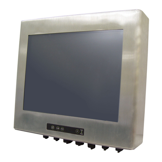
System Overview Introduction WTP-8865 Full IP65 panel PC is a high-performance computing for applications in harsh environments ,that comes with Intel Atom N270 Low Power processor, wide View-angle display (with sunlight readability), Sealing enclosure( 6 sides of IP65 certified) and Water proof I/O connectors for PS2, Ethernet , multi-COM port and USB interfaces. -
Page 13: System Specification
System Specification System Atom N270 1.6G 533MHz Chipset Intel® 945GSE chipset + ICH7M BIOS Award BIOS, ACPI supported Intel Generation 3.5 integrated GFX Core(133 MHz) on board Audio Realtek ALC286 Audio Codec, 2+2 watts power amplifier Marvell 88E8071 Gigabit Ethernet x 2 Memory One DDR2 SODIMM socket supports up to 2GB ICH7M... - Page 14 160/110 140 / 120 View Angle (H/V) Brightness (cd/m²) 500:1 700:1 Contrast Ratio Response Time (ms) (at 25°C) Power Consumption (W) LVDS LVDS Interface Supply Voltage (V) 2 lamps/2 side 2 CCFL Backlight Outline Dimensions 279x209x11 326.5 x 253.5 x 12 (mm) 1100 Weight (g)
- Page 15 Mini-PCI Mini-PCI-e X 1 socket External I/O DB-15 x 1 Audio Jack Triple (3x1) phone jack connector (Line-in, Line-out, and Mic-in) USB 2.0 x4 DB-9 x 3(External*3 internal *2) KB/Mouse PS/2 Connector x2 for keyboard/mouse RJ45 x2 for Gigabit Ethernet Power Power Input DC12V~28V...
- Page 16 For -20~55 degree Celsius operation temperature type When heater LED on, means heater is working to heat up system to working temperature range. a. Mother board operation system wake up time Ambient temperature (Celsius) mother board system wake up time (minute, ±...
-
Page 17: System View
System View WTP-8865-12 Outline Drawing... - Page 18 WTP-8865-15 Outline Drawing...
-
Page 19: I/O Connectors
I/O connectors... -
Page 20: Quick Installation Guide Of Full Ip65 Connectors
Quick Installation Guide of Full IP65 connectors Waterproof connectors pin assignments Power... - Page 24 COM Port...
- Page 25 Quick Installation Guide of Full IP65 connectors Step1. Open the covers on the connectors All IO on the button or rear side of WTP-8865 is well protected with a plastic cover. Before installing the WTP-8865 ,user needs to open it. Step2.
-
Page 26: Vesa Mount Installation
VESA mount installation Please use the supplied 4 x M4-L10 screws for VESA mounting. And as below VESA mounting holder is just a diagrammatic drawing. You can choose any standard VESA mounting holder to mount our machine. For use only with UL listed Wall Mount Bracket with minimum weight/load bearing capacity 10 Kg... -
Page 27: Unpacking
Unpacking After unpacking the shipping carton, you should find these standard items: WTP-8865 Full IP65 Panel PC series Accessory box including the followings: – AC adapter x 1 – AC power cord x 1 – CD-ROM for drivers, utility, user manual (in PDF format) Optional kits –... -
Page 28: Getting Started
Getting Started This chapter tells you how to set up the system. Setting Up the System The following is a summary of the steps in setting up the system for use. CAUTION: Make sure that power to the system and each of the devices to be connected is switched OFF before plugging in the connectors. - Page 29 Installing System Software Recent releases of operating systems from major vendors include setup programs, which load automatically and guide you through hard disk preparation and operating system installation. The guidelines below will help you determine the steps necessary to install your operating system on the Panel PC hard drive. NOTE: Some distributors and system integrators may have already pre-installed system...
- Page 30 Then you can use the external CD-ROM to transmit the software to the HDD that has been pre-installed in the WTP-8865 Panel...
-
Page 31: Installing The Drivers
Installing the Drivers After installing your system software, you will be able to set up the LAN, VGA, Audio and USB functions. All drivers are stored in a CD disc, which can be found in your accessory pack. The various drivers and utilities in the disc have their own text files that help users install the drivers and understand their functions. -
Page 32: Bios Setup Information
BIOS Setup Information BIOS Introduction The Award BIOS (Basic Input/Output System) installed in your computer system’s ROM supports Intel processors. The BIOS provides critical low-level support for a standard device such as disk drives, serial ports and parallel ports. It also adds virus and password protection as well as special support for detailed fine-tuning of the chipset controlling the entire system. - Page 33 select, the <PgUp> and <PgDn> keys to change entries, <F1> for help and <Esc> to quit. When you enter the Setup utility, the Main Menu screen will appear on the screen. The Main Menu allows you to select from various setup functions and exit choices.
-
Page 34: Standard Cmos Features
Note: If the system cannot boot after making and saving system changes with Setup, the Award BIOS supports an override to the CMOS settings that resets your system to its default. Warning: It is strongly recommended that you avoid making any changes to the chipset defaults. - Page 35 At the bottom of the menu are the control keys for use on this menu. If you need any help in each item field, you can press the <F1> key. It will display the relevant information to help you. The memory display at the lower right-hand side of the menu is read-only.
- Page 36 Time The time format is: Hour 00 to 23 Minute : 00 to 59 Second : 00 to 59 To set the time, highlight the “Time” field and use the <PgUp>/ <PgDn> or +/- keys to set the current time. IDE Channel Master/Slave The onboard Serial ATA connectors provide Primary and Secondary channels for connecting up to four Serial ATA hard disks.
- Page 37 Remarks: The main board supports 4 serial ATA ports and are represented in this setting as IDE Channel 2. Video This field selects the type of video display card installed in your system. You can choose the following video display cards: EGA/VGA For EGA, VGA, SEGA, SVGA or PGA monitor adapters.
-
Page 38: Advanced Bios Features
Advanced BIOS Features This section allows you to configure and improve your system and allows you to set up some system features according to your preference. Phoenix - Award BIOS CMOS Setup Utility Advanced BIOS Features CPU Feature Press Enter to configure the settings relevant to CPU Feature. Hard Disk Boot Priority... -
Page 39: Virus Warning
With the field, there is the option to choose, aside from the hard disks connected, “Bootable add-in Cards” which refers to other external devices. Virus Warning If this option is enabled, an alarm message will be displayed when trying to write on the boot sector or on the partition table on the disk, which is typical of the virus CPU L1 and L2 Cache Cache memory is additional memory that is much faster than... - Page 40 First/Second/Third Boot Device These fields determine the drive that the system searches first for an operating system. The options available include Hard Disk, CDROM,USB-FDD, USB-ZIP, USB-CDROM ,and Disabled. Boot Other Device These fields allow the system to search for an OS from other devices other than the ones selected in the First/Second/Third Boot Device.
- Page 41 second. Typematic Delay (Msec) When the typematic rate is enabled, this item allows you to set the time interval for displaying the first and second characters. By default, this item is set to 250msec Security Option This field allows you to limit access to the System and Setup. The default value is Setup When you select System, the system prompts for the User Password every time you boot up.
- Page 42 memory when used with OS/2 that depends on certain BIOS calls to access memory. The default setting is Non-OS/2. Report No FDD For WIN 95 If you are using Windows 95/98 without a floppy disk drive, select YES/NO to release IRQ6. This is required to pass Windows 95/98's SCT test.
-
Page 43: Advanced Chipset Features
Advanced Chipset Features This Setup menu controls the configuration of the chipset. Phoenix - Award BIOS CMOS Setup Utility Advanced Chipset Features DRAM Ting Selectable The logo appears at the right side of the monitor screen when the system is boot up. The default setting is SPD]. - Page 44 any program writes to this memory area, a system error may result Memory Hole At 15M-16M In order to improve performance, certain space in memory can be reserved for ISA cards. This memory must be mapped into the memory space below 16 MB. The choices are Enabled and Disabled. PCI Express Root Port Func By Default.
-
Page 45: Integrated Peripherals
Integrated Peripherals This section sets configurations for your hard disk and other integrated peripherals. Phoenix - AwardBIOS CMOS Setup Utility Integrated Peripherals OnChip IDE Device IDE HDD Block Mode This field allows your hard disk controller to use the fast block mode to transfer data to and from your hard disk drive. - Page 46 to transfer data to and from your hard disk drive. IDE Primary/Secondary Master/Slave PIO These fields allow your system hard disk controller to work faster. Rather than have the BIOS issue a series of commands that transfer to or from the disk drive, PIO (Programmed Input/Output) allows the BIOS to communicate with the controller and CPU directly.
- Page 47 KBC input clock Default is [12 MHz] Power ON Function This field is related to how the system is powered on – such as with the use of conventional power button, keyboard or hot keys. The default is BUTTON ONLY Onboard Serial Port These fields allow you to select the onboard serial ports and their addresses.
- Page 48 PWRON After RWR-Fail Default is [Off] This field sets the system power status whether on or off when power returns to the system from a power failure situation. USB Device Setting USB 1.0 Controller The options for this field are Enabled and Disabled. By default, this field is set to Enabled USB 2.0 Controller The options for this field are Enabled and Disabled.
-
Page 49: Power Management Setup
USB Mouse Function The options for this field are Enabled and Disabled. By default, this field is set to Enabled USB Storage Function The options for this field are Enabled and Disabled. By default, this field is set to Enabled Power Management Setup Phoenix –... - Page 50 Power Interface). ACPI Suspend Type The default setting of the ACPI Suspend mode is S3(STR RUN VGABIOS if S3 Resume The default setting of this field is Auto Power Management This field allows you to select the type of power saving management modes.
- Page 51 When enabled, the video is off in suspend mode. The default setting is Yes Suspend Type The default setting for the Suspend Type field is Stop Grant Modem Use IRQ This field sets the IRQ used by the Modem. By default, the setting is Suspend Mode When enabled, and after the set time of system inactivity, all devices except the CPU will be shut off.
- Page 52 Wake-Up by PCI card This field enables or disables the power on of the system through the LAN. Power on by Ring By default, this field is disabled. USB KB Wake-Up From S3 By default, this field is disabled. Resume by Alarm This field enables or disables the resumption of the system operation.
- Page 53 an IRQ to occur. When the operating system is ready to respond to the request, it interrupts itself and performs the service. Primary IDE 0 [Disabled] Primary IDE 1 [Disabled] Secondary IDE 0 [Disabled] Secondary IDE 1 [Disabled] FDD’COM’ LPT port [Disabled] PCI PIRQ[A-D]# [Disabled]...
- Page 54 PNP/PCI Configurations This option configures the PCI bus system. All PCI bus systems on the system use INT#, thus all installed PCI cards must be set to this value. Phoenix - AwardBIOS CMOS Setup Utility PnP/PCI Configurations Init Display First The default setting is Onboard Reset Configuration Data This field allows you to determine whether to reset the...
- Page 55 Resources Controlled by [Auto(ESCD)] This PnP BIOS can configure all of the boot and compatible devices with the use of a PnP operating system. PCI/VGA Palette Snoop Some non-standard VGA display cards may not show colors properly. This field allows you to set whether or not MPEG ISA/VESA VGA cards can work with PCI/VGA.
-
Page 56: Pc Health Status
PC Health Status This section shows the parameters in determining the PC Health Status. These parameters include temperatures, fan speeds and voltages. Phoenix - AwardBIOS CMOS Setup Utility PC Health Status Load Fail-Safe Defaults This option allows you to load the troubleshooting default values permanently stored in the BIOS ROM. -
Page 57: Load Optimized Defaults
Load Optimized Defaults This option allows you to load the default values to your system configuration. These default settings are optimal and enable all high performance features. Set Supervisor/User Password These two options set the system password. Supervisor Password sets a password that will be used to protect the system and Setup utility. -
Page 58: Exit Without Saving
Exit Without Saving Select this option to exit the Setup utility without saving the changes you have made in this session. Typing “Y” will quit the Setup utility without saving the modifications. Typing “N” will return you to Setup utility. -
Page 59: Appendix
Appendix A. Jumper Setting and Connectors List This appendix gives the definitions and shows the positions of jumpers, headers and connectors. All of the configuration jumpers on WTP-8865 Panel PC are in the proper position. The default settings shipped from factory are marked with (default). Jumpers Location and list In general, jumpers on the single board computer are used to select options for certain features. - Page 60 Jumper Definition JP1 & JP2 – LVDS Voltage choose Description Jumper Setting +3.3VS 1-2(default) +5VS JP3 – Touch Screen Configuration Description ON(Short) OFF(Open) Wire 5(default) JP5 – LVDS and DVI choose Description Jumper Setting LVDS 1-2, 4-5, 7-8, 10-11, 13-14, 16-17, 19-20, 22-23 (default) 2-3, 5-6, 8-9, 11-12, 14-15, 17-18, 20-21, 23-24 JP6 –...
- Page 61 JP9 –COM1 Function Selection Jumper Setting Illustration Description. 5-6,9-11,10-12,15-17,16-18 RS-232 3-4,7-9,8-10,13-15,14-16,21-22 RS-422 1-2,7-9,8-10,19-20 RS-485 JP10 – On board/Off board Touch Panel Selection Description Jumper Setting Touch screen On board All open Off board CAP/SAW/IR/Tempered glass Connector Definition PJ1 – HDD Power Connector Pin # Signal Description +12V...
- Page 62 Pin # Signal Description DC In (+12V~+28V) DC In (+12V~+28V) Ground Ground J1 – LCD Inverter Interface Pin # Signal Description +12V +12V Backlight Adjust Backlight Enable Ground Ground J2 – Touch Panel Interface Signal Description Pin # 8-wire 4-wire 5-wire Right Sense...
- Page 63 Left Sense Bottom Sense Top Sense Sense(S) Right Excite Right LR(X) Left Excite Left LL(L) Bottom Excite Bottom UR(H) Top Excite UL(Y) Ground Ground Ground J3 –Standard SATA Interface J4 – Fan Connect J5 – GPIO Interface(internal) Pin # Signal Description Pin # Signal Description GPO 1...
- Page 64 J6, J600 – LVDS Interface J6 (Channel 1) J38 (Channel 2) Pin # Signal Description Pin # Signal Description +LCD (+5V) +LCD (+5V) +LCD (+5V) +LCD (+5V) Ground Ground Ground Ground A_RxIn0- B_RxIn0- A_RxIn0+ B_RxIn0+ Ground Ground A_RxIn1- B_RxIn1- A_RxIn1+ B_RxIn1+ Ground Ground...
- Page 65 J10,J11 – Internal USB(internal) Pin # Signal Description +5VSB +5VSB Data - Data + Ground Ground J12 – Standard (IDE) Connector(internal) J13 – RTC Battery J14 – Power Switch J15 – Standard PCI Slot Interface J16 – 8051 JTAG Debug J17 –...
- Page 66 Power/Brightness/Sound Button /LCD_ON/OFF and LED Indicate JP2 Pin # Signal Description HDD_LED +5VSB +5VSB POWER_ON JP1 Pin # Signal Description Power Button +3.3VSB Sound Up Sound down Brightness Up Brightness Down LCD_ON/OFF J19 – Internal MIC Connect J20 – Parallel Port (internal)
- Page 67 Pin # Signal Description Pin # Signal Description Strobe Autofeed Data Bit 0 Error Data Bit 1 Initialize Data Bit 2 Select In Data Bit 3 Ground Data Bit 4 Ground Data Bit 5 Ground Data Bit 6 Ground Data Bit 7 Ground Acknowledge Ground...
- Page 68 J29 – KB+MS Connector J30 – Display Interface SIGNAL DESCRIPTION CRT_CON_RED Red analog video output CRT__CON_GREEN Green analog video output CRT__CON_BLUE Blue analog video output Monitor Sense Monitor Sense Ground Ground...
- Page 69 Ground Ground Monitor Sense CRT__CONN_DDDA Data from DDC monitor CRT_CONN_HSYNC Horizontal Sync control CRT_CONN_VSYNC Vertical Sync control CRT_CONN_DDCK Clock to DDC monitor J31 – Reset Button J32,J33,J34 – Audio Jack Pin # Signal Description 1(J32) Line In (stereo) Blue 2(J33) Microphone (stereo) Pink 3(J34) Line Out (stereo) Green...
- Page 70 Ring Indicator J35– COM1 Signal Description Pin # RS-232 RS-422 RS-485 Carrier Detect Transmit Data - Transmit Data - Receive Data Transmit Data + Transmit Data + Transmit Data Receive Data + Data Terminal Receive Data - Ready Ground Data Set Ready Request to Send Clear to Send Ring Indicator...
-
Page 71: Wake Up On Lan Function
B. Wake UP on LAN Function Please make sure the AC power is ON before use the function. 1. Boot into OS (windows XP). 2. In start menu control panel System device manager Network adapters double click Marvell Yukon 88E8071 Advance Wake from Shutdown Item select Wake on Magic packet from power off state. - Page 72 Please shutdown system and wait for wake on LAN after finish these procedures.
Need help?
Do you have a question about the WTP-8865 series and is the answer not in the manual?
Questions and answers