
Related Manuals for Wincomm WTP-9E66-15


Summary of Contents for Wincomm WTP-9E66-15
- Page 1 WTP-9E66 Series User’s Manual Version V 1.0 Copyright © 2017, ALL RIGHTS RESERVED. All other brand names are registered trademarks of their respective owner...
- Page 2 The information contained in this document is subject to change without any notices. Acknowledgments Greeting & Setup Thank you for purchasing the WTP-9E66 Panel PC. We wish that this unit will be durable and reliable in providing your needs. Please follow the instructions below to ensure the unit continues to have high performance Unpacking After opening the carton, there will be a unit with an accessory box.
- Page 3 If your hands are wet, do not touch the plug. Use your thumb and index finger, grip firmly on the power cord to disconnect from the electrical socket. By pulling the power cord, may result in damaging it. If the unit is not going to be in use for an extended period of time, remember to disconnect the unit. Connect the unit to a power source with the same numerical value as spec.
- Page 4 If smoke or strange odor is flowing out of the open frame unit. If the power cord or plug is damaged. When the functions of the unit are dysfunctional. When part replacement is needed. Make sure service technician uses replacement parts specified by the manufacturer, or those with the same characteristics and performance as the original parts.
- Page 5 Version Change History Date Version Description Remark 2017/11/07 V1.0 First release...
-
Page 6: Table Of Contents
How to Use This Manual ............ 1 Specifications ............2 Table Stand Assemble Instruction ......7 Wall Mount Stand Assemble Instruction ....8 System View ..............11 Setting up the System ............13 Installing System Software ..........14 Installing the Drivers ............14 BIOS Setup Information ......... -
Page 7: How To Use This Manual
How to Use This Manual This manual is written for the system integrator, PC technician and knowledgeable PC end user. It describes how to configure your WTP-9E66 Panel PC to meet various operating requirements. The user’s manual is divided into three chapters, with each chapter addressing a basic concept and operation of the server board. -
Page 8: Specifications
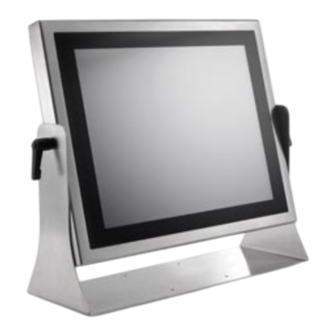
Specifications System FCBGA1356 6th generation Intel® Core i7/i5/i3 processor (15W max.) Chipset Intel® integrated HD Graphics 520 by CPU Audio Realtek ALC262 Audio Codec, 2+2 watts power amplifier Intel i219LM x 1 (Vpro support) + i210AT x 1 Memory Two 2133 MHz DDR4 SODIMM socket support dual Channel, non-ECC, up to 32GB Serial ATA SATA 3, 600 MB/s transfer rate x 2 Serial port RS232,422,485 x 1 /RS232 x 5... - Page 9 19” Display Brand Resolution (pixel) SXGA 1280(x3) x 1024 Model name G190EG01 Active Area (mm) 376.32 (H) x 301.06(V) Number of Colors 16.7M View Angle (H/V) 170 / 160 Brightness (cd/m2) Contrast Ratio 1000:1 Response Time (ms) (at 25°C) Backlight Weight (g) 1670 life time<Hrs>...
- Page 10 External water/dust resistant I/O (rear side) 1 x M12 8pin for USB 1/2 1 x M12 8pin for USB 3/4 1 x M12 8pin for COM 1/RS-232 1 x M12 8pin for COM 2/RS-232/422/485 RS-232: TxD, RxD, RTS, CTS, DTR, DSR, DCD, GND 1 x M12 8pin for LAN 1 Power 1 x M12 5pin DC power connector...
- Page 11 Regulatory FCC, CE (EMC), VCCI class B Configurations: 1. WTP-9E66-15, Core i5-6200U CPU, 2.30GHz, 4G RAM, 500G HDD, 4 USB, 2 COM, 1 LAN 2. WTP-9E66-19, Core i5-6200U CPU, 2.30GHz, 4G RAM, 500G HDD, 4 USB, 2 COM, 1 LAN 3.
- Page 12 Operation system: 1. Windows 7 embedded, Windows 7 pro (64bit, 32 bit) 2. Windows 8 embedded, Windows 8 industrial (64bit) 3. Windows 10 (64bit)
-
Page 13: Table Stand Assemble Instruction
Table Stand Assemble Instruction Step 1. Please check out the following parts before assemble. Item Quantity Table Stand Black Silicone Washer Black Handle Step 2. Please follow the picture diagrams to assemble. Explode View Step 3. Please tighten the black handle in a clockwise direction. -
Page 14: Wall Mount Stand Assemble Instruction
Wall Mount Stand Assemble Instruction Step 1. Please check out the following parts before assemble. - Page 15 Item Quantity Wall Mount Stand Black Silicone Washer Black Handle Step 2. Please follow the picture diagrams to assemble. Explode View Step 3. Please tighten the black handle in a clockwise direction.
-
Page 17: System View
System View WTP-9E66-15 Outline Drawing... - Page 18 WTP-9E66-19 Outline Drawing...
- Page 19 WTP-9E66-22 outline drawing...
-
Page 20: Setting Up The System
Setting up the System The following is a summary of the steps in setting up the system for use. CAUTION: Make sure that power to the system and each of the devices to be connected is switched OFF before plugging in the connectors. Make any required external connections such as the keyboard, and mouse. - Page 21 Follow the sequence below to install the drivers: Step 1 – Install Intel® INF Driver Step 2 – Install Intel® VGA Driver Step 3 – Install Intel® LAN Driver Step 4 – Install Audio Driver Step 1 – Install Intel® INF Driver 1.
-
Page 22: Bios Setup Information
BIOS Setup Information BIOS Introduction The AMI BIOS (Basic Input / Output System) installed in your computer system’s ROM supports Intel processors. The BIOS provides critical low-level support for a standard device such as disk drives, serial ports and parallel ports. It also adds virus and password protection as well as special support for detailed fine-tuning of the chipset controlling the entire system. - Page 23 Advanced Trusted Computing Configuration Enables or disables BIOS support for security device. O.S. will not show Security Device. TCG EFI protocol and INT1A interface will not be available. ACPI Settings Enable Hibernation Enables or Disables System ability to Hibernate (0S/S4 Sleep State). This option may be not effective with some OS.
- Page 24 Un-Configure ME OEMFlag Bit 15:Un-Configure ME without password. Serial Port Configuration Serial Port 1 Configuration Serial Port Select an optimal settings for super IO Device. Change Settings Select an optimal settings for Super IO Device. Set Parameters of Serial Port 1. Serial Port 2 Configuration Serial Port Enable or Disable Serial Port (COM).
- Page 25 Active Processor Cores Number of cores to enable in each processor package. Intel Virtualization Technology When enabled, a VMM can utilize the additional hardware capabilities provided by Vanderpool Technology. Intel(R) SpeedStemp(tm) Allows more than tow frequency ranges to be supported. Turbo Mode Enable / Disable Turbo Mode.
- Page 26 mSATA for RTD3. SATA DEVSLEP Idle Timeout config Enable/Disable SATA DTIO Config Serial-ATA Port 1 Enable / Disable Serial ATA Port 0. Port 0 Enable or Disable SATA Port HotPlug Designates this port as hot Pluggable. External SATA External SATA Support Spin Up Device On an edge detect from 0 to 1, the PCH starts a COMRESET initialization sequence to the device.
- Page 27 On an edge detect from 0 to 1, the PCH starts a COMRESET initialization sequence to the device. SATA Device Type Identify the SATA port is connected to Solid State Drive or Hard Disk Drive. Topology Identify the SATA Topology if it is Default or ISATA or Flex or DirectConnect or Device Sleep mSATA for RTD3.
- Page 28 Chipset System Agent (SA) Configuration System Agent (SA) Parameters. VT-d VT-d capability Graphics Configuration Graphics Turbo IMON Current Graphics Turbo IMON current values supported(14-31) Skip Scaning of External Gfx Card If Enable, it will not scan for external Gfx Card on PEG and PCH PCIE Ports Primary Display Select which of IGFX/PEG/PCI Graphics device should be Primary Display or Select SG for Switchable GFX.
- Page 29 Memory configuration Parameters PCH-IO Configuration PCI Express Configuration PCI Express Configuration settings USB Configuration USB Precondition Precondition work on USB host controller and root ports for faster enumeration. PCI Express Configuration settings XHCI Disable Compliance Mode Options to disable Compliance Mode. Default is FALSE to not disable Compliance Mode.
- Page 30 Security Administrator Password Set Administrator Password. User Password Set user Password. T S64GSSD370 : : : : HDD Security Configuration for selected drive. Secure Boot menu Secure Boot Secure Boot can be enabled if 1.System running in User mode with enrolled Platform key(PK).
- Page 31 Boot Setup Prompt Timeout Number of seconds to wait for setup activation key. 65535(0xFFFF) means indefinite waiting. Bootup Numlock State Selects the keyboard NumLock state. PXE Boot PXE Network Boot Enable / Disable. Quiet Boot Enable or disables Quiet Boot option. Boot Option #1 Sets the system boot order.
- Page 32 Save Changes and Exit Exit system setup after saving the changes. Discard Changes and Exit Exit system setup without saving any changes. Save Changes and Reset Reset the system after saving the changes. Discard Changes and Reset Reset system setup without saving the changes. Save Changes Save the changes done so far to any of setup options.
-
Page 33: Appendix
Appendix A. Jumper settings and Connectors This appendix gives the definitions and shows the positions of jumpers, headers and connectors. All of the configuration jumpers on WTP-9E66 are in the proper position. Jumper and Connector Definition Block... - Page 34 JP1 – Touch Panel Type Selection Description Jumper Setting 3M type 1-2, 3-4 (default) ELO type 5-6,7-8 JP2 – PCT/RES Touch Selection Description Jumper Setting PCT Touch RES Touch JP3 –TPM2.0 Pin # Signal Description Pin # Signal Description DEBUG_CLK LPC_FRAME# SMBCLK PLT_RST#...
- Page 35 JP5 – Backlight Type Selection Description Jumper Setting Analog Inverter PWM Inverter JP6 – Sensor Selection Description Jumper Setting No Panel Sensor 1-2(default) No MB Sensor 3-4(default) Reserved JP7 –Panel Resolution Selection JP8 – Backlight control level Selection Description Jumper Setting +3.3V OPEN (default)
- Page 36 JP9 – Heater Test Selection Description Jumper Setting Normal Open (default) Heater Test JP10 –GPO Settings Description Jumper Setting Off (NA) On (1-2, 3-4, 5-6, 7-8 short) JP11 –GPI Settings Description Jumper Setting On (1-2, 3-4, 5-6, 7-8 short) Off (NA) JP12 –...
- Page 37 JP15 – SATA / SATADOM Selection Description Jumper Setting SATA 2-3(default) SATA DOM JP16 – COM1 RI# / 12VS / 5VS Selection Description Jumper Setting 12VS 5-6(default) JP17 – COM4 Power Selection Description Jumper Setting +5VS 2-3(default) +12VS JP18 – COM2 RI# / 12VS / 5VS Selection Description Jumper Setting 12VS...
- Page 38 1.1 Connector Definition PJ1 /PJ2 – HDD Power Connector Pin # Signal Description +12VS +5VS PJ3 – Battery Connector Pin # Signal Description BATT+ BATT+ BATT+ BATT_T BATT_CLK BATT_DAT BATT_EN# Ground Ground Ground PJ4 – Power Jack Pin # Signal Description DC In DC In...
- Page 39 PJ5 – Power Input Connector Pin # Signal Description DC In DC In...
- Page 40 J1, J48, J49 – Internal USB 2.0 Pin Header Pin # Signal Description +5VSB +5VSB Data - Data + J2 – LCD Inverter Wafer Header Pin # Signal Description +12VS +12VS Backlight Control Backlight Enable...
- Page 41 J3 – MB Heater Connector Pin # Signal Description +12VSB J4, J5, J6, J7 – Panel Heater Connector Pin # Signal Description +12VSB J8 – Internal USB 2.0 Pin Header for Webcam Pin # Signal Description +5VSB +5VSB Data - Data + J9 –...
- Page 42 Data - Data + J10 – Resistance Touch Screen Interface Signal Description Pin # 8-wire 4-wire 5-wire UL(X+) UL(X+) UL(X+) UR(Y+) UR(Y+) UR(Y+) PROBE LR(X-) LR(X-) LR(X-) LL(Y-) LL(Y-) LL(Y-) X+_DRIVE Y+_DRIVE X-_DRIVE Y-_DRIVE J11 – LVDS Interface Pin # Signal Description Pin # Signal Description...
- Page 43 A_TXD1- B_TXD1- A_TXD0+ B_TXD0+ A_TXD0- B_TXD0- +LVDS PWR +LVDS PWR +LVDS PWR +LVDS PWR...
- Page 44 J12 – Panel Temp Sensor Connector Pin # Signal Description PANEL_SENSOR J13 – 80 Port Pin # Signal Description Pin # Signal Description LPC_AD0 +5VS LPC_AD1 +3.3VS LPC_AD2 L80HLAT LPC_AD3 L80LLAT J14 – M.2 E_Key Pin # Signal Description Pin # Signal Description +3.3V USB_D+...
- Page 45 USB_D- RSVD RSVD PETP0 PETN0 CLINK Reset(I)(0/3.3V) CLINK DATA (I/O) PERP0 CLINK CLK(I/O) PERN0 COEX3(I/O)(0/1.8V) COEX2(I/O)(0/1.8V) REFCLKP0 COEX1(I/O)(0/1.8V) REFCLKN0 SUSCLK(32kHz)(I)(0/3.3V) PERST0#(0/3.3V) CLKREQ0#(I/O)(0/3.3V) BT_DISABLE2#(I)(0/3.3V) PEWAKE0#(I/O)(0/3.3V) W_DISABLE1#(I)(0/3.3V) RSVD RSVD RSVD +3.3V +3.3V...
- Page 46 J15 – Heater Error / Heating LEDs Pin # Signal Description +3.3V_ALWAYS HEATER_LED# ERROR_LED# J16 – Light Sensor Connect Pin # Signal Description +3.3VS Ground SMBCLK LIG_SEN_INT# SMBDATA J17 –TPM / ID-394 Pin # Signal Description Pin # Signal Description...
- Page 47 +3.3VSB SUS_STAT# SMB DATA SMB CLK Debug CLK CLKRUN# LPC Frame# +5VSB LPC AD3 +3.3VS LPC AD2 SERIRQ LPC AD1 PLT reset# LPC AD0 J18 – GPIO Connect Pin # Signal Description Pin # Signal Description GEN_GPI1 GEN_GPO1 GEN_GPI2 GEN_GPO2 GEN_GPI3 GEN_GPO3 GEN_GPI4...
- Page 48 232_EC_SIN 232_EC_SOUT +5V_ALWAYS +3.3V_DSW J20 / J21 – DDR4 SO-DIMM Interface H5.2mm H9.2mm...
- Page 49 J22 – EC Reset connector Pin # Signal Description WRST#...
- Page 50 J23–PCIE X4 Slot for ISO Interface Pin # Side B Side A Pin # Side B Side A +5VSB +3.3VSB Ground USBPN +5VSB +3.3VSB LPC_UART24M Ground +5VSB +3.3VSB Ground Ground +5VSB +3.3VSB Ground Ground +5VSB +3.3VSB Ground Ground +5VSB +3.3VSB Ground Ground Ground...
- Page 51 +3.3VS CSC_DET# SCK_OUT SDA_OUT SPI_PROG SPI_CLK SPI_DO SPI_DI SPI_CS J25 – Battery Socket J26 – JTAG For EC Pin # Signal Description Pin # Signal Description Reserved Reserved +3.3V Reserved +3.3V +3.3V...
- Page 52 J27 – Mini PCI Express / mSATA Socket Pin # Signal Description Pin # Signal Description WAKE# +3.3VSB Reserved Reserved +1.5VS CLKREQ# Reserved Reserved REFCLK- Reserved REFCLK+ Reserved Reserved Reserved Reserved Reserved PERST# PERn0 +3.3VSB PERp0 +1.5VS SMB_CLK PETn0 SMB_DATA PETp0 USB_D- USB_D+...
- Page 53 J28 – Standard SATA / SATA DOM Interface Pin # Signal Description Ground Ground Ground / +5VS J29 – BIOS Socket Pin # Signal Description Pin # Signal Description CS0# MOSI MISO SCLK HOLD +3.3VS...
- Page 54 J30 – Standard SATA Interface Pin # Signal Description Ground Ground Ground J31 – CAP Front Bezel Button Pin # Signal Description +5VSB +3.3VSB KP_SCL KP_SDA PWR_LED# KP_P_LED SATA_LED#...
- Page 55 J32–PCIE X4 Slot Interface Pin # Side B Side A Pin # Side B Side A +12VS RSVD RSVD RXN0 +12VS +12VS RSVD +12VS TXP1 RSVD TXN1 SMBCLK RSVD SMBDATA RSVD RSVD TXP2 +3.3VS_PCIE RSVD TXN2 RSVD +3.3VS_PCIE +3.3VSB +3.3VS_PCIE PCIE_WAKE# PLT_RST# TXP3...
- Page 56 J34 – Internal COM4 TTL Serial Port Pin # Signal Description Pin # Signal Description TTL_DSR# TTL _DCD# TTL _RTS# TTL _SIN TTL _CTS# TTL _SOUT TTL _RI# TTL _DTR# +5VS/+12VS J35 – PS2 KB/MS Pin # Signal Description KBDATA MSDATA Ground +5VSB...
- Page 57 J36 – Internal COM5 Serial Port Pin # Signal Description Pin # Signal Description 232_DSR# 232_DCD# 232_RTS# 232_SIN 232_CTS# 232_SOUT 232_RI# 232_DTR# +5VS J37 – Internal COM4 Serial Port Pin # Signal Description Pin # Signal Description 232_DSR# 232_DCD# 232_RTS# 232_SIN 232_CTS# 232_SOUT...
- Page 58 J38 – Internal COM3 Serial Port Pin # Signal Description Pin # Signal Description 232_DSR# 232_DCD# 232_RTS# 232_SIN 232_CTS# 232_SOUT 232_RI# 232_DTR# +5VS J39 – Internal MIC Connect Pin # Signal Description MIC_R MIC_L J40 – Power / HDD LED Pin # Signal Description SATA_LED#...
- Page 59 PWR_LED# J41 – Internal COM6 Serial Port Pin # Signal Description Pin # Signal Description 232_DSR# 232_DCD# 232_RTS# 232_SIN 232_CTS# 232_SOUT 232_RI# 232_DTR# +5VS/+12VS J42 / J43 –External RJ45 Ethernet Port Activity/Link LED Status Description No Link Blinking Data Activity Link Speed LED Status...
- Page 60 J44,J45 – DisplayPort Interface Pin # Signal Description Pin # Signal Description ML_LANE0+ ML_LANE3- ML_LANE0- CONFI G1 ML_LAN1+ CONGI G2 AUX_CH+ ML_LAN1- ML_LANE2+ AUX_CH- HOT PLUG ML_LANE2- RETURN ML_LANE3+ +3.3VS J46, J47 – RIGHT / LEFT CH for Speaker. Signal Description Pin # J50 (RIGHT CH) J51 (LEFT CH)
- Page 61 J50 – Internal COM2 Serial Port Pin # Signal Description Pin # Signal Description 232_DSR# 232_DCD# 232_RTS# 232_SIN 232_CTS# 232_SOUT 232_RI# 232_DTR# +5VS/+12VS J51 – Internal COM1 Serial Port Pin # Signal Description Pin # Signal Description 232_DSR# 232_DCD# 232_RTS# 232_SIN 232_CTS# 232_SOUT...
- Page 62 Pin # Signal Description +12VSB J54 – Power Switch connect Pin # Signal Description Power ON J55,J56 – USB3.0 Port Pin # Signal Description Pin # Signal Description Data1- Data2- Data1+ Data2+ SSRX1- SSRX2- SSRX1+ SSRX2+ SSTX1- SSTX2- SSTX1+ SSTX2+...
- Page 63 J57 – Reset Connector Pin # Signal Description SYS_RESET# J58 – Reset Button Pin # Signal Description SYS_RESET# J59 / J60 – External Audio Phone Jack Audio Jack Signal Description Line Out (stereo) Green Microphone (stereo) Pink...
- Page 64 J61 – External COM1 Connector Signal Description Pin # RS-232 RS-422 RS-485 TX D- DATA- TX D+ DATA+ RX D+ RX D- J62 – External COM2 Connector Pin # Signal Description Pin # Signal Description...
-
Page 65: B. Touch Lock Ap User's Manual
This Touch Lock Tools Application Program (AP) and related documentation are available for whom has signed and returned a copy of the AP Licensing Agreement to Wincomm. Contact Wincomm account manager if you require a copy of the software. Touch Lock Tools AP Requirement... - Page 66 2.3.3 You can see the Touch Lock Tools form and min keyboard as below. 2.3.4 You can change touch lock timer (range 1-100 / 1-99 means 1-99 seconds / 100 means always lock). By set value in textbox and click “Set” button. If setting success, it will show message as follow.
- Page 67 If setting timer value error, it will show error message as follow. 2.3.5 If touch lock is enable, you will see the timer in the lower right corner of the screen, and icon in task bar will become red . 2.3.6 If timer countdown to zero, touch will unlock automatically, and icon in task bar will become green.
-
Page 68: Getting Help
2.3.8 When you click “Minimize” button, the form will concealed below Task Bar. 2.3.9 When you click “Exit” button, program will disable WDT and close. 3. Getting Help If assistance is required when running the AP, please contact your account manager.
Need help?
Do you have a question about the WTP-9E66-15 and is the answer not in the manual?
Questions and answers