
Related Manuals for Beretta NOVELLA 55-64-71 RAP


Summary of Contents for Beretta NOVELLA 55-64-71 RAP
- Page 1 Installation Manual NOVELLA 55-64-71 RAP Boilers | Cast Iron Base Installation Manual...
- Page 2 The following symbols are used in this manual: CAUTION! = Indicates actions that require caution and adequate preparation STOP! = Identifies actions that you MUST NOT do...
-
Page 3: Table Of Contents
CONTENTS 1 SAFETY INFORMATION AND PRECAUTIONS ..........2 DESCRIPTION OF THE APPLIANCE ............5 2.1 Description ............................... 2.3 Main parts of the boiler ..........................2.2 Control panel ............................2.4 Technical specifications ........................... 2.5 Identification ............................. 2.6 Material supplied ............................. 2.7 Handling ..............................2.8 Overall dimensions and water fittings ..................... -
Page 4: Safety Information And Precautions
1 SAFETY INFORMATION AND PRECAUTIONS This manual and the operation manu- Observe the following precautions to ensure al associated with it form integral parts safe operation of the boiler: of the product. Make sure that they are always kept with the boiler even if it is Do not allow children or uninformed per- transferred to another owner or user, or sons to operate the boiler... -
Page 5: Description Of The Appliance
2 DESCRIPTION OF THE APPLIANCE Description NOVELLA RAP boilers are gas fuelled boil- The key features of these boilers include: ers for domestic heating. They are equipped with an atmospheric burner and a cast iron - piezoelectric ignition with thermocouple primary heat exchanger. -
Page 6: Main Parts Of The Boiler
Main parts of the boiler Control panel Boiler temperature sensor socket Piezoelectric ignition system Safety thermostat Water circuit drain cock Thermocouple Burner Gas supply solenoid valve Name plate Control panel Main switch Central heating temperature control Central heating temperature gauge Flue gas thermostat (manual reset) LED indicator (flue gas temperature alarm) LED indicator (mains power) -
Page 7: Technical Specifications
Technical specifications Description Rated heat input in central heating mode 61,0 70,5 79,0 kcal/h 52460 60630 67940 Rated heat output in central heating mode 55,0 63,5 71,1 kcal/h 47300 54600 61150 Consumption Boiler class II 2H3+ Power supply V ~ Hz 230 ~ 50 Index of protection Losses from stack and casing with burner off... -
Page 8: Identification
Identification NOVELLA boilers are identified by a product name plate giving the boiler’s serial number, model and main technical and performance data. It is essential to specify the correct model of boiler when ordering spare parts or requesting technical assis- tance. -
Page 9: Handling
Handling Once you have removed the packaging, pro- ceed as follows to handle the boiler: - remove the screws securing the boiler to the wooden pallet - remove the front panel (P) and top panel (C) from the casing (fig. 2.5) Fig. -
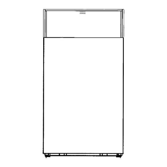
Page 10: Overall Dimensions And Water Fittings
Overall dimensions and water fittings Fig. 2.9 Description Water circuit Water circuit drain cock CH circuit temperature control sensor Safety thermostat sensor CH circuit temperature gauge sensor CH flow CH return GAS Gas supply Fig. 2.10... - Page 11 Boiler’s water-side pressure drop NOVELLA boilers come without a pump. A In order to choose a pump of the right size, bear in mind the boiler’s water-side pressure pump must therefore be provided as part of drop, as shown in the following graph. the installation.
-
Page 12: Wiring Diagram
2.10 Wiring diagram Fig. 2.14... -
Page 13: Installation
3 INSTALLATION Installation standards Installation in existing sys- The boiler must be only be installed by quali- fied personnel in conformity to applicable Perform the following checks before installing NOVELLA boilers in existing systems: standards. Installers must also ensure conformity to fire - Check that the flue is large enough and prevention standards, gas safety standards suitable for the characteristics of the boiler... -
Page 14: Water Connections
Water connections NOVELLA boilers are designed and made for use in central heating systems, but can also be used to generate domestic hot water if connected to a suitable storage cylinder. The specifications of the water fittings are as follows: CH outlet 1”1/4 F CH return... - Page 15 - Remove the control panel (1) by pulling it towards you. - Unscrew the fixing screw (3) to release the control panel from its housing (2) and access its internal parts. Fig. 3.2 - Unscrew the two fixing screws and remove the protective cover (4) from the casing.
-
Page 16: Gas Connections
Gas connections NOVELLA boilers must be connected to the methane or LPG gas supply in conformity to applicable standards (fig. 3.6). Perform the following checks before making the connection: - check that the boiler is compatible with the type of gas supply - check that the gas supply pipes are thor- oughly clean Fit a suitably sized filter in the gas supply pipe... -
Page 17: Flue Gas Vent And Air Intake
Flue gas vent and air intake Flues and stack connections must be made in conformity to all applicable local and national laws and standards. The use of rigid pipes is mandatory. All joints between pipe sections must be hermetically sealed and all parts of the flue must be resist- ant to high temperatures, condensate and mechanical stress. -
Page 18: Filling The Water Circuit
Filling the water circuit NOVELLA series boilers must be fitted with a water circuit filling system connected to the boiler return line (fig. 3.8). Fig. 3.8 - Make sure that the boiler drain cock is closed before attempting to fill the boiler (fig. -
Page 19: Start-Up And Functioning
4 START-UP AND FUNCTIONING Preliminary checks Remove the front panel of the boiler and perform the following checks before switching the boiler on or testing any of its functions: - check that the fuel and water circuit shut-off cocks are open - check that the type and pressure of the gas supply are as specified for the boiler - check that the water circuit pressure gauge shows a pressure over 1 bar with the system cold. - Page 20 - Open the boiler’s front panel, then press the ignition knob on the gas valve and turn it to the “1” position (fig. 4.9) Fig. 4.9 - Keep holding down the ignition knob and simultaneously press the button on the pie- zoelectric igniter (near the “4”...
-
Page 21: Final Checks
Final checks Once the boiler has started up, make sure that it shuts down and re-starts properly when the following actions are taken: - The boiler’s thermostat control is turned down (fig. 4.12) Fig. 4.12 - The power switch on the control panel is switched OFF (fig. - Page 22 REPLACING THE NOZZLES Burner nozzles - Unscrew the two methane nozzles from the burner and replace them with the LPG noz- zles. Use the aluminium seals provided in the kit (fig. 4.17). Fig. 4.17 Pilot flame nozzle - Disconnect the pilot flame gas pipe (1) from the gas valve and from the support plate (2) (fig.
-
Page 23: Shut-Down
5 SHUT-DOWN - Press the power switch on the control panel (fig. 5.1) Fig. 5.1 - Turn the mains power switch OFF (fig. 5.2) Fig. 5.2 - Close the boiler’s fuel cock and water circuit cock (fig. 5.3). Empty the central heating system if there is any risk of freezing. -
Page 24: Maintenance
6 MAINTENANCE To maintain maximum functionality and effi- Scheduled maintenance ciency, and to comply with applicable legisla- tion, have the boiler serviced at regular inter- vals. Scheduled maintenance normally consists of The frequency at which servicing should be the following operations: performed depends on installation and oper- ating conditions. -
Page 25: Optional Accessories
7 OPTIONAL ACCESSORIES - Wall-mounted weekly timer thermostat (fig. 7.1) Fig. 7.1 - RO120 storage cylinder (fig. 7.2) Fig. 7.2 - Back draught shutter Ø 180 cod. 480213 Ø 200 cod. 480214 Fig. 7.3... - Page 28 Via Risorgimento, 23 A 23900 - Lecco www.berettaboilers.com Beretta is constantly improving its products and therefore reserves the right to modify the characteristics and specifications of the appliance described in this manual at any time and without prior notice. The contents of this manual are not contractually binding on the...
Need help?
Do you have a question about the NOVELLA 55-64-71 RAP and is the answer not in the manual?
Questions and answers