Advertisement
Quick Links
Advertisement

Related Manuals for Heta SCAN-LINE AQUA


Summary of Contents for Heta SCAN-LINE AQUA
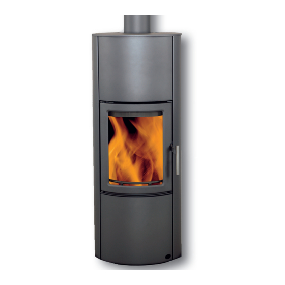
- Page 1 SCAN-LINE AQUA www.heta.dk...
- Page 2 TABLE OF CONTENTS Installation ................. 2-4 Operating instructions .............. 4-8 Connecting to a water system…..........9-11 Installing and commissioning Heta Aqua Kit K 36-20 ..13-17 Schematic diagrams............... 18-19 INSTALLATION Installing the stove For minimum clearance require-...
- Page 3 rating in the same room as the to accommodate the flue gas pipe. stove can weaken the chimney The thimble and flue gas pipe must draught, which can effect the not penetrate the chimney opening stove’s efficiency. It can also lead itself, but must be flush with the in- to smoke escaping into the room side of the chimney duct.
- Page 4 as well as the ambient wind and - the chimney and flue gas pipe are weather conditions also affect the blocked ability to generate sufficient nega- - the house is sealed (no through- tive pressure in the chimney. draught) Before lighting a stove that has not - negative pressure (poor draught been used for a long time, check conditions) due to a cold chimney...
- Page 5 before storage, and should be of an the start-up handle fully to the left appropriate length (approx. 22–30 (front view). See Fig. 4. cm) so they can be laid evenly on the embers. Firewood stored outdoors should be covered. Oben Examples of combustion values for Closed different woods...
- Page 6 Hot embers can remain in condary air so that it ignites the flue the ash for a long time. Stove data as per EN 13240 testing. Scan-Line Aqua Particle Flue gas Nominal...
- Page 7 BLOCKAGE If smells or smoke escape from the the chimney, be aware that soot, etc. stove, it is important to establish can collect in the smoke chamber whether the chimney is blocked. A behind the stones. Excessive chimney small amount of draught is always draught may cause wood to burn required to ensure satisfactory ope- too quickly.
- Page 8 Emptying the ashpan (Figs. 5-8) Clearing soot after chimney sweeping and repla- cing the stones. (Figs. 9-12). WARRANTY Heta stoves undergo extensive Warning quality control before delivery Unauthorised modification to our suppliers. of the stove and the use of non-original parts will void Your product is therefore guarante- your warranty.
- Page 9 Attaching an outside air supply (if required) Figs. 5–8. Fig. 13 Fig. 14 Feed a duct through the hole in the back plate. Cut out and remove the metal cover plate as shown using a diagonal cutter. Fig. 15 Fig. 16 Secure the duct using a collar band.
- Page 10 As Heta A/S is unable to give advice on every type of installation, we have produced this guide to help you choose the best method of installing your stove.
- Page 11 Open expansion means that the valve and emergency cooling cir- expansion tank (in this case located cuit. The emergency cooling circuit at the top of the installation) is consists of a spiral-shaped pipe open to the atmosphere. It must be built into the water tank, which is large enough to accommodate the connected directly to a cold water...
- Page 12 ing. We therefore recommend instal- ling an automatic air vent to allow trapped air to escape. Fig. 4 Example of an automatic air Fig. 5 System for maintaining the vent correct temperature 1: Tank 1: Cold water return 2: Air pocket preventing circulation 2: Hot water supply 3: Automatic air vent (in this case, open) 3: Circulation thermostat...
- Page 13 Example: Opened and closed expansion systems Temperature sensor Thermal protection* Water connection* Drain* Central gas or oil boiler *Closed expansion Radiator and / or floor heating Submersible Connection thermostat- Bleed 0006-5009 TC 2 valve – E11513 Pressure relief valve SYR tempe- rature valve Grundfos 0006-5005 ¾”...
- Page 14 AQUA KIT K 36-20 1. GENERAL 1.3 Functional description 1.1 Scope These instructions describe the Heta return-flow loading valve as- function, installation, commissioning sembly K36-20 prevents the boiler and operation of Heta return-flow from sooting by raising the return temperature controller K36-20. For...
- Page 15 from the boiler circuit in the con- bypass completely. This allows the trol valve. This maintains constant water from the accumulation tank return-flow temperature to the to flow directly into the boiler. boiler and prevents the formation of condensation in the boiler. tKR >...
- Page 16 grease or other products used resulting from seals that have be- during installation contain mineral come damaged through exposure to oil. We accept no responsibility and mineral oil. do not guarantee against damage 3 ASSEMBLY AND INSTALLATION [Expert] 3.1 Assembly of return-flow loading valve assembly 1.
- Page 17 The stove must never be used there is a risk of explosion, leading without water and a functio- to irreparable damage! ning cold water supply [KV] Note: Thermal drain protection is / drain [KA] in the thermal not mandatory in Denmark when drain protection and relevant using open expansion.
- Page 18 4 TECHNICAL DATA Return-flow loading valve K36 DN 20 ________________________________________________ Connectors on heat production equipment: 1” external thread to accumulation tank ¾” internal thread ________________________________________________ Materials Fixtures brass Seals EPDM/paper Insulation EPP Hydraulics Max. temperature: 110°C Max. pressure 4 bar Kvs value 5.3 ________________________________________________ 5 PERFORMANCE...
Need help?
Do you have a question about the SCAN-LINE AQUA and is the answer not in the manual?
Questions and answers