Advertisement
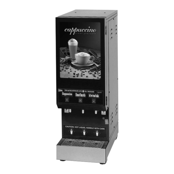
Powdered Beverage Dispenser
Model GB3M10-LD
Safety Information..................2
Installation...............................3
Operation ................................6
Cleaning...................................8
Thank you for purchasing this quality powdered beverage dispenser. For your safety and the safety of others,
read all warnings and the operator manual before installing or using the product. Properly instruct all operators.
Keep training records. For future reference, record serial number here:
Grindmaster-Cecilware
4003 Collins Lane, Louisville, KY 40245 USA
Phone: 502.425.4776 Toll Free: 800.695.4500
Fax: 502.425.4664
Web: gmcw.com Email: info@gmcw.com
©2016 Grindmaster-Cecilware
Printed in USA
GB Models 1, 2, 3, 4, 5, & 6
Model GB1HC
Table of Contents
Maintenance .........................10
Troubleshooting Guide.........13
Parts Diagram and List..........15
Wiring Diagrams ...................23
Operator Manual
Model GB5M10-LD
Grindmaster-Cecilware provides the industry's
BEST warranty. Visit gmcw.com for warranty
terms and conditions.
0516 Form # CW-314-01
Part # 390-00013
Advertisement
Table of Contents

Related Manuals for Cecilware GB3M10-LD


Summary of Contents for Cecilware GB3M10-LD
-
Page 1: Table Of Contents
Thank you for purchasing this quality powdered beverage dispenser. For your safety and the safety of others, read all warnings and the operator manual before installing or using the product. Properly instruct all operators. Keep training records. For future reference, record serial number here: Grindmaster-Cecilware provides the industry’s Grindmaster-Cecilware BEST warranty. Visit gmcw.com for warranty 4003 Collins Lane, Louisville, KY 40245 USA terms and conditions. -
Page 2: Safety Information
To avoid damaging unit, turn on power and wait for tank to fill with water before turning on heater. Observe machine voltage configuration. Do not apply improper voltage to machine or damage to machine will occur. Do not use extension cord. Cecilware GB Series ®... -
Page 3: Installation
In addition: damage, contact the shipper, not Grindmaster- 1. A quick disconnect water connection or enough Cecilware. extra coiled tubing (at least 2x the depth of the unit) so that the machine can be moved for After the machine has been unpacked and placed on a cleaning underneath. - Page 4 THERMOSTAT PRODUCT LABEL DRAIN HOSE W/PLUG DISPENSE BUTTON WATER INLET HOSE POWER SWITCH WHIPPER MOTOR PILOT LIGHT FOR BLOWER DUCT HOSE POWER HEATER CORD FAN/BLOWER SPOUT RINSE SWITCH DRIP TRAY WATER INLET VALVE RELAY/TIMER DRIP TRAY Cecilware GB Series ®...
- Page 5 1/2" (1.3cm) If you need help, call Grindmaster-Cecilware Technical from the probe. If it does, the tank is not Service Department, (502) 425-4776 or (800) 695-4500 (USA &...
-
Page 6: Operation
Mixing Chamber, as shown. TRIANGULAR RIB 3. To DECREASE the water temperature - simply turn the Thermostat Knob one notch counter-clockwise to the next lower dial setting. CORRECT WATER LEVEL FOR MAX FLOW RATE. MIXING CHAMBER Cecilware GB Series ®... - Page 7 FOR COFFEE: The machine is factory adjusted to dispense 0.3 gr./sec per OZ. Cup. [1.5 grams of coffee product per 5 oz. of liquid (in a 6 oz. cup). The recommended throw is 1.5 to 1.8 grams per 6 oz. cup of Coffee, with 80% fill. GB Series Cecilware ®...
-
Page 8: Cleaning
18.940 “Tolerance exemptions for active and inert ingredients for use in antimicrobial formulations (Food-contact surface sanitizing solutions)”. Follow the instructions provided with the sanitizing agent. Let all sanitized parts drain and air dry. DO NOT WIPE THEM DRY. Cecilware GB Series ®... - Page 9 AUGER BUSHING FRONT NUT [2] FLANGE/ NUT AUGER AUGER BUSHING-BACK PRODUCT GUIDE MIX BOWL SOCKET DISPENSE CUP MIXING CHAMBER BASE MOUNT GROMMET SLINGER DISC WHIPPER CHAMBER TWIST TO REMOVE MOUNTING BASE 'O'-RING #125 EXTENSION TUBE WHIPPER BLADE GB Series Cecilware ®...
-
Page 10: Maintenance
Remove molded door front by removing side screws. Slide out clear plastic panel with picture. Replace picture and slide the plastic panel w/ new picture into the door frame. Then put front molded door back on with screws on the sides. To replac Cecilware GB Series ®... - Page 11 Repair Kit M491QL. • Lift up black tabs, remove trough drawer. • Clean and replace trough drawer. • Remove hose assembly from the motor. • Clean out and replace hose. WATER FLOW ADJUSTMENT Dispense Valve Chamber Mount GB Series Cecilware ®...
- Page 12 DUAL PROBE LIQUID LEVEL CONTROLLER N L1 SOLENOID TO PROBE GROUNDING PLATE IN SINGLE L398C [120V] BACK OF THE DUAL L690A [120V] BOARD SINGLE L399C [220V] GROUND DUAL L706A [220V] TERMINAL WATER INLET VALVE SS WATER LEVEL CONTROL CCA Cecilware GB Series ®...
-
Page 13: Troubleshooting Guide
Turn Thermostat ON. Turn Knob separate Thermostat) Clockwise. Loose connection on Thermostat. Make sure all wires and terminals on Thermostat are tight. Hi-Limit Temperature Switch is Replace the Hi-limit. defective. Heater is burned out or defective. Replace the Heater. GB Series Cecilware ®... - Page 14 Troubleshooting Guide (continued) If you still need help, call Grindmaster-Cecilware Technical Service Department, (502) 425-4776 or (800) 695-4500 option 2 (USA & Canada only) (Monday through Friday 8 AM - 6 PM EST). Please have the model and serial number ready so that accurate information can be given.
-
Page 15: Parts Diagram And List
STRAIGHT CD316-black MOUNTING BASE CD65A SLANTED CD362-white SLANTED CD362-white MOUNTING BASE CD65A-white / CD317-black M379A 'O'-RING #125 M379A 'O'-RING #125 EXTENSION TUBE M467A EXTENSION TUBE WHIPPER BLADE CD64A M467A - white WHIPPER BLADE CD64A H306A-stainless steel GB Series Cecilware ®... - Page 16 TWIST TO REMOVE STRAIGHT CD63A-white STRAIGHT CD316-black MOUNTING BASE CD65A STRAIGHT CD316-black SLANTED CD362-white MOUNTING BASE CD65A M379A 'O'-RING #125 SLANTED CD362-white M379A 'O'-RING #125 WHIPPER BLADE CD64A EXTENSION TUBE M467A EXTENSION TUBE M467A WHIPPER BLADE CD64A Cecilware GB Series ®...
- Page 17 Parts Diagram and List (continued) Tank Assembly GB Series Cecilware ®...
- Page 18 N T C O I N S TA S P R E S N D T E I N S T A OF F H E AT R in se S er ve *See Metal Parts List Cecilware GB Series ®...
- Page 19 Parts Diagram and List (continued) Unit Assembly (GB2 SKI-SUPER shown) T E R *See Metal Parts List GB Series Cecilware ®...
-
Page 20: Parts List
ß ß ß ß SIDE PANELS - SEE METAL PARTS LIST - NEXT PAGE LAMP HOLDER B216AL B216AL B216AL B216AL B216AL B216AL TWIN TUBE BULB 16W CE82AL CE82AL CE82AL CE82AL CE82AL CE82AL (240V-USE CE80AL TWIN 18W) Cecilware GB Series ®... - Page 21 RN21QL RN21PL RQ78AL RQ16QL TB34QL RR71BL (RIGHT) GB2-Super-SKI Super SKI RN21CL RN16CL RQ78AL RQ16AL RN61Q RN33A M703A M704Q M892AL-FRONT CLEAR 0.040 SJ61QL TANK & M892ML-BACK GB6M SJ61CL SM14AL SM13AL TF43CL SL76AL MILKY 0.060 M893AL-CLEAR WINDOW 0.125 GB Series Cecilware ®...
- Page 22 M326AL M326AL M326AL M326AL DRAIN PLUG M391AL M391AL M391AL M391AL M391AL M391AL M391AL M391AL PLUG, SILICON M494AL M494AL M494AL M494AL M494AL M494AL M494AL M494AL * EXPORT MODELS DISPENSE VALVE - L676AL HEATER, 240V 3000W - G266AL Cecilware GB Series ®...
-
Page 23: Wiring Diagrams
GB1, GB1M, GB1MD (120V, 1700W, 1 PH, 2 wires + Ground) w/ Relay DUAL LIQUID LEVEL CONTROL WATER INLET VALVE 1 FILL 2 AC-1L 3 AC-2N 4 L-LEVEL 5 H-LEVEL WATER 6 COMMON LEVEL PROBES WATER TANK GB Series Cecilware ®... - Page 24 GB2, GB2M, GB2M, 2K (120V, 1700W, 1 PH, 2 wires + Ground) w/ Relays DUAL LIQUID LEVEL CONTROL WATER INLET VALVE 1 FILL 2 AC-1L 3 AC-2N 4 L-LEVEL 5 H-LEVEL WATER 6 COMMON LEVEL PROBES WATER TANK Cecilware GB Series ®...
- Page 25 GB2, 2M, 2MD, 2K, [120/240V, 3KW, 1PH, L1, L2, NTL, GND] W/RELAYS DUAL LIQUID LEVEL CONTROL WATER INLET VALVE 1 FILL 2 AC-1L 3 AC-2N 4 L-LEVEL 5 H-LEVEL WATER 6 COMMON LEVEL PROBES WATER TANK GB Series Cecilware ®...
- Page 26 GB3, GB3M, GB3MD, 3K (120V, 1700W, 1 PH, 2 wires + Ground) w/ Relay DUAL LIQUID LEVEL CONTROL WATER INLET VALVE 1 FILL 2 AC-1L 3 AC-2N 4 L-LEVEL 5 H-LEVEL WATER 6 COMMON LEVEL PROBES WATER TANK Cecilware GB Series ®...
- Page 27 BLUE DUAL LIQUID LEVEL CONTROL WATER INLET VALVE 1 FILL 2 AC-1L 3 AC-2N 4 L-LEVEL 5 H-LEVEL WATER 6 COMMON LEVEL PROBES WATER TANK THERMOSTAT FUSE 6A HEATER SWITCH HEATER 3KW-HEATER HI-LIMIT LIGHT POWER SWITCH GB Series Cecilware ®...
- Page 28 Wiring Diagrams (continued) GB3M, 3K (120V/240, 6kW, 1 PH, L1, L2, +NTL + GND) w/ Relays Cecilware GB Series ®...
- Page 29 Wiring Diagrams (continued) GB3M-W [120V, 1.7KW, 1 PH, 2 WIRES + GROUND] W/ RELAYS DUAL LIQUID LEVEL CONTROL WATER INLET VALVE 1 FILL 2 AC-1L 3 AC-2N 4 L-LEVEL 5 H-LEVEL WATER 6 COMMON LEVEL PROBES WATER TANK GB Series Cecilware ®...
- Page 30 GB4, GB4M, 4M-8, 4MD [120V, 1.7KW, 1 PH, 2 WIRES + GROUND] W/ RELAYS DUAL LIQUID LEVEL CONTROL WATER INLET VALVE 1 FILL 2 AC-1L 3 AC-2N 4 L-LEVEL 5 H-LEVEL WATER 6 COMMON LEVEL PROBES WATER TANK Cecilware GB Series ®...
- Page 31 Wiring Diagrams (continued) GB5M [120V, 1.7KW, 1 PH, 2 WIRES + GROUND] W/ RELAYS GB Series Cecilware ®...
- Page 32 Wiring Diagrams (continued) GB6M 120V GB6M-10-LD-U Cecilware GB Series ®...
- Page 33 5 H-LEVEL 6 COMMON LEVEL PROBES WATER TANK 3 TANK HEATERS - 1 PHASE - 6 KW FUSE TRANSFORMER HEATER LIGHT 120V 220V POWER CONTACTOR SWITCH 3 2 1 110V COIL THERMOSTAT HEATER SWITCH HI-LIMIT 10GA 10GA GB Series Cecilware ®...
- Page 34 TEACH-ME TIMER TIMER DISPENSE SWITCH DISPENSE SWITCH STOP SW. HOT WATER SW. DUAL LIQUID LEVEL CONTROL WATER INLET VALVE 1 FILL 2 AC-1L 3 AC-2N 4 L-LEVEL WATER 5 H-LEVEL 6 COMMON LEVEL PROBES WATER TANK Cecilware GB Series ®...
- Page 35 GB Series Cecilware ®...
- Page 36 Grindmaster-Cecilware 4003 Collins Lane, Louisville, KY 40245 USA Phone: 502.425.4776 Toll Free: 800.695.4500 Fax: 502.425.4664 Web: gmcw.com Email: info@gmcw.com 0516 Form # CW-314-01 ©2016 Grindmaster-Cecilware Part # 390-00013 Printed in USA...
Need help?
Do you have a question about the GB3M10-LD and is the answer not in the manual?
Questions and answers