Advertisement
Quick Links
Advertisement

Related Manuals for Body Solid G-STACK


Summary of Contents for Body Solid G-STACK
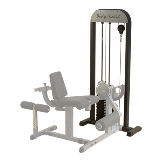
- Page 1 G-STACK ASSEMBLY INSTRUCTIONS...
- Page 2 S T E P Be careful to assemble all components in the sequence they are presented. Attach Lower Main Frame (A) to the Upper Main Frame (B) as shown using: Four 27 (3/8” x 4” hex head bolt)* Eight 31 (3/8” washer) Four 37 (3/8”...
- Page 3 S T E P...
- Page 4 S T E P Be careful to assemble all components in the sequence they are presented. Install chrome guide rods (D) into the holes in the lower frame. Install weight raiser (15) and rubber donut (4) and slide to bottom of the guide rod.
- Page 5 S T E P...
- Page 6 S T E P Be careful to assemble all components in the sequence they are presented. Install pulleys (2) into frame with bolt (25), washer (31), and nylon lock nut (37). Fully tighten bolts. Install cable end bolt (26) into frame with washers (31) and nylon lock nuts (37).
- Page 7 S T E P...
- Page 8 S T E P Be careful to assemble all components in the sequence they are presented. Install cable by first assembling the ball end of the cable into the selector rod top bolt (11) and attaching the cable cylinder lock over the ball end. Secure with provided allen screw.
- Page 9 S T E P WARNING Selector Rod Top Bolt (11) must be threaded a minumum of 1/2” into the Selector Rod (12), and Jam Nut (33) tightened securely against spring lock washer (34) to ensure proper connection. Check the Jam Nut (33) once a week to make sure it is tight.
- Page 10 Install pulley shrouds (C) onto frame with screws (24) and washers (30). Fully tighten screws. Attach completed assembly to Body Solid Inner / Outer Thigh or Leg Press machine. Bolts (E1), washers (E2), nylon nuts (E3), backing plate and extension link bar will be supplied with either of the exercise stations.
- Page 11 S T E P...
- Page 12 G STACK Main Frame Parts List KEY# PART# DESCRIPTION STCKMF-A LOWER MAIN FRAME STCKUMF-B UPPER MAIN FRAME STCKSD-C SHROUD STCKGR-D GUIDE ROD STCKFPB-E FLOATING PULLEY BRACKET Key #, Part #, and Discription are required when ordering parts.
- Page 13 G STACK Hardware List KEY# PART# DESCRIPTION CFC23 FOOT CAP 2” X 3” CPP4.25 PULLEY 4 1/4” OD SHAFT COLLAR RUBBER DONUT LANYARD CLAN CWSP WEIGHT STACK PIN CCES CABLE END SHAFT SELECTOR ROD TOP BOLT CSRTB SELECTOR ROD CTP10 TOP PLATE 10lbs 15/20 CWSP10...
- Page 14 ® 1900 S. Des Plaines Ave. Forest Park, Il 60130 1 (800) 556-3113 Hours: M-F 8:30 - 5:00 www.bodysolid.com Copyright 2009. Body-Solid. All rights reserved. Body-Solid reserves the right to change design and specifications when we feel it will improve the product. Body-Solid machines maintain several patented and patent pending features and designs.
Need help?
Do you have a question about the G-STACK and is the answer not in the manual?
Questions and answers