
Related Manuals for Body Solid Sissy GSS50


Summary of Contents for Body Solid Sissy GSS50
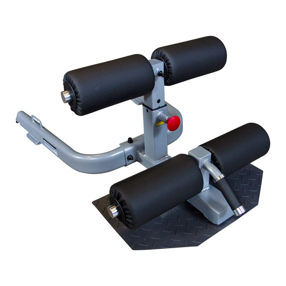
- Page 1 GSS50 & A s s e m b l y I n s t r u c t i o n s O W N E R ’ S M A N U A L V. GSS50-081518...
- Page 2 W a r n i n g , S a f e t y & M a i n t e n a n c e Be sure that all users carefully read and understand all warning, safety and maintenance labels on the machine before each use.
-
Page 3: Table Of Contents
T a b l e o f C o n t e n t s • SAFETY INSTRUCTIONS......PAGE 4 • PREPARATION..........PAGE 5 • HARDWARE ILLUSTRATION......PAGE 6 • PART / HARDWARE LIST ......PAGE 9 • ASSEMBLY INSTRUCTIONS......PAGE 10 • EXPLODED VIEW.......... -
Page 4: Safety Instructions
I m p o r t a n t S a f e t y I n s t r u c t i o n s Before beginning any fitness program, you should obtain a complete physical examination from your physician. Il est conseille de subir un examen medical complet avant d’entreprendre tout programme d’exercise. Si vous avez des etourdissements ou des faiblesses, arretez les exercices immediatement. -
Page 5: Preparation
P r e p a r a t i o n Thank you for purchasing the GSS50. This bench is part of the Body-Solid line of quality strength training machines, which lets you target specific muscle groups to achieve better muscle tone and overall body conditioning. To maximize your use of the equipment please study this Owner’s Manual thoroughly. Required Tools Assembly Tips The basic tools that you must obtain before assembling Read all “Notes” on each page before beginning each the GSS50 include but are not limited to: step. While you may be able to assemble the GSS50 using the m Metric Allen Key Set illustrations only, important safety notes and other tips are included in the text. m Standard Allen Key Set m Standard Wrench Set Some pieces may have extra holes that you will not use. -
Page 6: Hardware Illustration
G S S 5 0 H a r d w a r e I l l u s t r a t i o n Part #1 SOCKET HEAD CAP SCREW M10X100mm QTY. 2 Part #2 SOCKET HEAD CAP SCREW M10X60mm QTY.2 Part #3 SOCKET HEAD CAP SCREW M10X35mm QTY. 2 Part #4 FLAT HEAD CAP SCREW M8x20mm QTY. 2 Part #5 HEX HEAD BOLT M6x50mm QTY. 2 45 6... - Page 7 G S S 5 0 H a r d w a r e I l l u s t r a t i o n Part #6 SET SCREW M4x3mm QTY. 6 Part #7 SOCKET HEAD CAP SCREW M6x16mm QTY.1 Part #8 LARGE O.D. WASHER M10 QTY. 2 Part #9 FLAT WASHER M10 QTY. 4 Part #10 M10 LOCK WASHER QTY. 2 ...
- Page 8 Part #11 LOCK WASHER M6 QTY. 1 Part #12 NYLON LOCK NUT M10 QTY.2 Part #13 JAM NUT M10 QTY. 2 Part #14 NYLON LOCK NUT M6 QTY. 2 ...
-
Page 9: Part / Hardware List
G S S 5 0 P a r t s L i s t / I l l u s t r a t i o n Part# Description BASE FRAME U FRAME FOOT PLATE HEIGHT ADJUSTMENT TUBE FOAM ROLLER TUBE M10x100mm SOCKET HEAD CAP SCREW M10x60mm SOCKET HEAD CAP SCREW M10x35mm SOCKET HEAD CAP SCREW M8x20mm FLAT HEAD CAP SCREW... -
Page 10: Assembly Instructions
S T E P Be careful to assemble all components in the sequence they are presented. NOTE: Wrench tighten ALL hardware at the end of each STEP . Some components may be pre-assembled. Nylon lock nuts will not fully screw onto bolts, they must be wrench tighten to fully go on. - Page 11 S T E P Above shows Step 1 assembled and completed.
- Page 12 S T E P Be careful to assemble all components in the sequence they are presented. NOTE: Wrench tighten ALL hardware at the end of each STEP . Some components may be pre-assembled. Nylon lock nuts will not fully screw onto bolts, they must be wrench tighten to fully go on.
- Page 13 S T E P Above shows Step 2 assembled and completed.
- Page 14 N o t e s...
-
Page 15: Exploded View
G S S 5 0 E x p l o d e d V i e w... -
Page 16: Contact Page
GSS50 PLEASE WRITE YOUR SERIAL NUMBER IN THE BOXES BELOW 014640-��-��-����-���� S/N # 1900 S. Des Plaines Ave. Forest Park, IL 60130 Phone:(708)427-3555 Fax:(708)427-3556 Hours: M-F 8:30 - 5:00 CST www.bodysolid.com Copyright 2009. Body-Solid. All rights reserved. Body-Solid reserves the right to change design and specifications when we feel it will improve the product. Body-Solid machines maintain several patented and patent pending features and designs.
Need help?
Do you have a question about the Sissy GSS50 and is the answer not in the manual?
Questions and answers