
Related Manuals for JAI AD-081CL


Summary of Contents for JAI AD-081CL
- Page 1 User's Manual AD-081CL Digital 2CCD Progressive Scan HDR / High Frame Rate Camera Document Version: 1.1 AD-081CL_Ver.1.1_July2012...
- Page 2 JAI Ltd., Japan and may only be used by the purchasers of the product. JAI Ltd., Japan makes no warranty for the use of its product and assumes no responsibility for any errors which may appear or for damages resulting from the use of the information contained herein.
- Page 3 AD-081CL Supplement The following statement is related to the regulation on “ Measures for the Administration of the control of Pollution by Electronic Information Products “ , known as “ China RoHS “. The table shows contained Hazardous Substances in this camera.
-
Page 4: Table Of Contents
AD-081CL - Table of Contents - General ................... - 4 - Camera nomenclature ................- 4 - Main Features ..................- 5 - Locations and functions ................ - 6 - Pin configuration ................- 7 - 12-pin multi connector (DC in / Trigger in) ..........- 7 - Digital Output Connector (Camera Link ) .......... - Page 5 8.2.9 Setup-Y (Command BLY1 and BLY 2) ............ - 37 - Load and Save functions ..............- 37 - AD-081CL Command list ..............- 38 - AD-081CL Camera Control Tool ............- 42 - Camera Control Tool Interface ............- 42 - 9.1.1 Camera Control Tool Bar ..............
-
Page 6: General
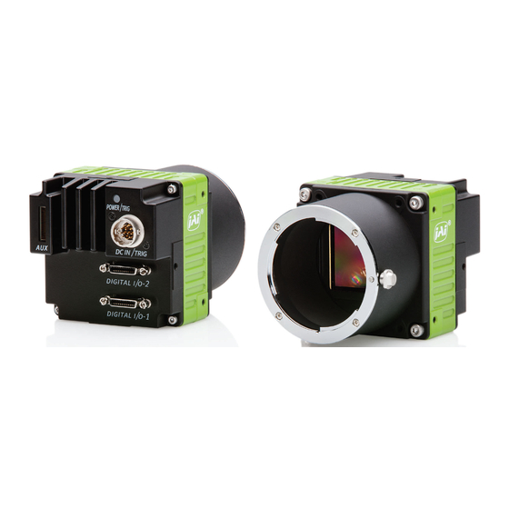
The AD-081CL is equipped with continuous mode, pre-select trigger mode, pulse width trigger mode and PIV (Particle Image Velocimetry) mode. The AD-081CL uses a standard Camera Link interface, whereby each channel can output images with 8- or 10-bit depth. Camera nomenclature The standard camera composition consists of the camera main body and Sensor protection cap. -
Page 7: Main Features
AD-081CL Main Features 2-monochrome progressive scan CCDs (1/3”) mounted on an optical prism Member of the C3 Advanced series 1024 (h) x 768 (v) active pixels per channel 4.65 μm square pixels Two Camera Link connectors provided for separate or combined output ... -
Page 8: Locations And Functions
: M3, max length 5mm (Note 1 ) AD-081CL uses Prism Optics. C-mount lens should be designed for interfacing to a 3-CCD camera. Rear protrusion of the C-mount lens must be less than 4mm to avoid damage to the prism. -
Page 9: Pin Configuration
AD-081CL Pin configuration 5.1 12-pin multi connector (DC in / Trigger in) In/Out Name Remarks Type: HR-10A-10R-12PB (Hirose) male DC (+12V) in (Seen from rear of the camera) Iris Video For Auto iris lens XEEN1 Negative Logic XEEN2 Trigger1 External trigger... -
Page 10: Input And Output Circuits
The pin configuration of 26-pin connector conforms to Camera Link BASE configuration. However, since AD-081CL camera has various outputs, pin assignment depends on the specific output mode selected. For details, please refer the table shown on the next page. - Page 11 AD-081CL Camera Link connector - 2 Camera Link Connector - 1 Port/ 10bit 8bit 10bit 8bit Pin No. Signal 10bit 8bit 8bitoutp 10bit 8bit 10bit 10bit 8bit output output output output output output output * note ) * Note )
-
Page 12: Advise On Camera Settings
Advise on camera settings 6.1 Lens considerations AD-081CL utilizes prism optics for separating the incident light onto the two CCDs. The camera employs a C-mount for the lens but for high image quality it is strongly recommended to use lenses specifically designed for 3-CCD cameras. -
Page 13: Configuring Camera Link Outputs (Command: Os1, Os2)
The AD-081CL can operate in continuous mode to support applications not requiring an external trigger. This mode permits the use of a lens with video controlled iris. The AD-081CL uses the signal from imager 1 (BW1) for this purpose. The external trigger signal can be input through pins number 10 and 11 of the 12-pin HIROSE connector. -
Page 14: Digital Video Output (Bit Allocation)
AD-081CL 7.1.4 Digital Video output (Bit allocation) 1023 White Clip Level The 10-bit digital output is set at 890 LSB as 100% video 100% Level level when CCD output is 200mV. The white clip level is set at 1023 LSB when CCD output is 230mV. -
Page 15: Auto-Detect Lval-Sync / Async Accumulation
AD-081CL 7.1.6 Auto-detect LVAL-sync / async accumulation This function replaces the manual setting found in older JAI cameras. Whether accumulation is synchronous or asynchronous in relationship to LVAL depends on the timing of the trigger input. When a trigger is received while FVAL is high (during readout), the camera works in LVAL-synchronous mode, preventing reset feed-through in the video signal. -
Page 16: Electronic Shutter (Commands Sm1,Sm2,Sh1,Sh2,Pe1,Pe2)
AD-081CL 7.1.9 Electronic shutter (Commands SM1,SM2,SH1,SH2,PE1,PE2) The AD-081CL has two shutter modes. One is an 11-step pre-set shutter and the other is a programmable exposure mode which can be controlled from 0.5L to 792L in one-line increments. Pre-set Shutter (SH1 / SH2) The setting command is from SH1/SH2=0(OFF) to SH1/SH2=11(1/50,000)... -
Page 17: Piv (Particle Image Velocimetry) Mode
A high frame rate (double speed) can be achieved by shifting the exposure timing of BW1 and BW2 by 1/2 frame duration. As the AD-081CL operates at the rate of 30 fps in continuous mode, this will produce a rate of 60 fps in high frame rate mode (double speed mode). The shutter speed must be less than 1/60s (396L). -
Page 18: High Dynamic Range Function
The AD-081CL camera uses this shutter function to simultaneously capture two images with different shutter speeds. As a result, the AD-081CL can output two identical images with different video levels, one for capturing the details in the dark portion and the other for maintaining details in the brightest portions of the image. -
Page 19: Knee Compensation (Commands Kn1,Kn2,Ksy1/Ksy2,Kpy1/Kpy2)
The camera operates at 12 bits internally and has 1279 1335 2048 LSB dynamic range. However, the output of AD-081CL is 8-bit or 10-bit and 1023 the data over 1023 LSB (in case of 10-bit) is clipped if 1/16 Knee the relationship between IN and OUT is set at linear. -
Page 20: Test Signal Generator (Commands: Pby1,Pby2)
AD-081CL 7.1.17 Test Signal Generator (Commands: PBY1,PBY2) AD-081CL is equipped with a test signal generator. The following test signals are selected by commands, PBY1 and PBY2. PBY1 / PBY2 : 0= Video, 1=Bypass, 2= Test pattern1 (Gradation), 3= Test Pattern 2 (White 100%) 7.1.18... -
Page 21: Horizontal Timing
AD-081CL 7.2.2 Horizontal Timing The horizontal timing for continuous mode, full frame and partial scan are shown below. 1 c k = 3 3 . 7 5 0 M H z ( 2 9 . 6 3 n s / c k ) -
Page 22: Vertical Timing
AD-081CL 7.2.3 Vertical Timing The vertical timing for continuous mode and full frame scan are shown below. 1L = 1420Clock (42.07us) F V A L p e r i o d F V A L 7 9 2 L L V A L... -
Page 23: Partial Scan
AD-081CL 7.2.4 Partial Scan The vertical timing for continuous mode and partial scan is shown below. The horizontal timing for partial scan is the same as full scan. Back Blank Line Front of Start SC Option Output Image Frame (Line) - Page 24 AD-081CL Vertical Timing for 1/4 Partial scan 1Line = 1420Clock (42.07us) F V A L p e r i o d 3 4 8 L 3 4 4 L F V A L L V A L H i g h S p e e d...
- Page 25 AD-081CL Horizontal Timing (Common for Full and Partial Scans) 1 c k = 3 3 . 7 5 0 M H z ( 2 9 . 6 3 n s / c k ) L V A L p e r i o d...
-
Page 26: Vertical Binning
AD-081CL 7.2.5 Vertical binning The vertical timing chart and horizontal timing for the vertical binning mode is as follows. Horizontal timing 1 c k = 3 3 . 7 5 0 M H z ( 2 9 . 6 3 n s / c k ) -
Page 27: Operating Modes
AD-081CL 7.3 Operating modes The AD-081CL can function as a high frame rate (double speed readout) camera or a high dynamic range camera. Most of the camera‟s main operating modes can be configured to work with either camera setup. Only PIV mode is an independent function. - Page 28 AD-081CL Basic configuration to use this function Mode Setting Command Process mode High frame rate HF=1 In case of trigger mode Trigger PS, PW TR1/TR2= 1,2 Output mode Separate IS=1 ( Separate) Common setting Output Select 8 bit, 10 bit...
-
Page 29: High Dynamic Range Function
AD-081CL 7.3.2 High Dynamic Range function A high dynamic range image or video stream can be obtained by compositing during post processing two images or video streams which have different exposure times. The maximum dynamic range is achieved when: One camera is set at 1/30s shutter speed... -
Page 30: Pre-Select Trigger Mode
AD-081CL 7.3.4 Pre-Select trigger mode An external trigger pulse initiates the capture, and the exposure time (accumulation time) is defined by the SH or PE commands. The resulting video signal will start to be read out after the selected shutter time. - Page 31 AD-081CL Fig.28. PS trigger mode (LVAL async) timing chart 1L = 1420 clock (42.07us) Ext.Trig FVAL LVAL Exposure Period XEEN (Hirose 12pin) 1 to 2L (Exposure) Data out Delay Exposure Delay 13 to 14L 14.2us DATA out Fig. 29. PS trigger mode (LVAL async details)
- Page 32 AD-081CL Fig.30. PS trigger mode (LVAL sync) timing chart Edge Pr e- Sel ect mod e ( Full Frame ) (LVAL sync ) 1L = 1420 Cl ock ( 42. 07us ) Ext . Tr i g FVAL LVAL Exposure Period...
-
Page 33: Pulse Width Trigger Mode
AD-081CL 7.3.5 Pulse Width trigger mode In this mode, the accumulation time is equal to the trigger pulse width. Here it is possible to have long exposure times. For the best image quality, the maximum recommended time is <60 frames (2 seconds), however longer exposures may produce acceptable results depending on the application. - Page 34 AD-081CL Puls e Widt h mode( Full Frame) (LVAL aSYNC) 1L = 1420 clock ( 42. 07us ) Del ay of Expos ur e End Ext . Tr i g 32. 1us FVAL LVAL Exposure Period XEEN (Hirose 12pin) 1 to 2L...
-
Page 35: Piv Mode (Particle Image Velocimetry)
AD-081CL 7.3.6 PIV mode (Particle Image Velocimetry) PIV mode is an independent function and is not to be combined with the High Frame Rate function, the High Dynamic Range function, or the normal output mode (Sync or Separate). In this mode, one trigger input provides three consecutive outputs. A strobe light is used for illumination. -
Page 36: Smearless Mode
AD-081CL 7.3.7 Smearless mode This function can reduce the smear on highlights within the image. This is effective for both PS and PW trigger modes. Before the accumulation starts, stored charges are read out at high speed. This can reduce the smear in the upper areas of the object without affecting the lower areas. -
Page 37: Modes And Functions Matrix
AD-081CL 7.4 Modes and functions matrix AD-081CL has two output modes when the external trigger pulse is used. One is “Synchronous” mode and the other is “Separate” mode. In Synchronous mode, two Camera Link outputs are synchronized with each other, whereas in Separate mode, two Camera Link outputs are not synchronized. -
Page 38: Configuring Camera
Configuring Camera 8.1 Serial communications All configuration of the AD-081CL camera is done by LVDS via Camera Link. Baud rate is 9600 bps. The camera can be set up from a PC running terminal emulator software, or through a graphical user interface (GUI) using JAI's camera control software. -
Page 39: Setting Functions
8.2 Setting functions 8.2.1 Output mode (Command IS) AD-081CL has two imagers and this function selects synchronized output for both imagers or individual output for each imager. This function should be set at first. IS=0 is synchronous output and IS=1 is separate output. -
Page 40: Ad-081Cl Command List
AD-081CL 8.4 AD-081CL Command list Command Format Parameter Remarks A – General settings and utility commands ゙ EB=[Param.]<CR><LF> 0=Echo off Echo Back Off at power up EB?<CR><LF> 1=Echo on Camera Status ST?<CR><LF> Actual setting Request Online Help Request HP?<CR><LF> Command list 3 digits, (e.g.) - Page 41 AD-081CL Command Format Parameter Remarks PE1=[Param.]<CR><LF> Available when PE1?<CR><LF> SM1=1 Programmable 0 to 792 Exposure PE2=[Param.]<CR><LF> Available when PE2?<CR><LF> SM2=1 D – Trigger mode 0=Normal (Continuous) TR1=[Param.]<CR><LF> For Imager BW1 1=PS(Pre select) TR1?<CR><LF> 2=PW (Pulse width) Trigger Mode 4=PV1 TR2=[Param.]<CR><LF>...
- Page 42 AD-081CL Command Format Parameter Remarks BLY1=[Param.]<CR><LF> For Imager 1 BLy2?<CR><LF> Setup Level Y -128 to 256 BLY2=[Param.]<CR><LF> For Imager 2 BLy2?<CR><LF> AGC1=[Param.]<CR><LF> For Imager 1 AGC1?<CR><LF> 0=AGC OFF AGC Select 1=AGC ON AGC2=[Param.]<CR><LF> For Imager 2 AGC2?<CR><LF> AGR1=[Param.]<CR><LF> For Imager 1 AGR1?<CR><LF>...
- Page 43 AD-081CL Command Format Parameter Remarks I – Other functions 0=Video PBY1=[Param.]<CR><LF> 1=Bypass For Imager BW1 PBY1?<CR><LF> 2=Test Pattern 1 3=Test Pattern 2 Process Bypass 0=Video PBY2=[Param.]<CR><LF> 1=Bypass For Imager BW2 PBY2?<CR><LF> 2=Test Pattern 1 3=Test Pattern 2 CM1=[Param.]<CR><LF> For Imager BW1 CM1?<CR><LF>...
-
Page 44: Ad-081Cl Camera Control Tool
AD-081CL AD-081CL Camera Control Tool The Camera Control Tool for Windows 2000/XP can be downloaded from www.jai.com. The control tool contains a camera control program and a developer's kit for integrating the control tool in your own software. For the integrator and experienced user, the Camera Control Tool is much more than a program with a Windows interface. - Page 45 AD-081CL 9.1.3 Communication Window The Communication Window is used to connect the Camera Control Tool with the JAI camera. Camera Link communication: Select “Camera Link” “Category” box. “Port Name” indicates DLL file names (or frame grabber names) for all Camera Link frame grabbers that are installed in the pc.
-
Page 46: Common Control Window
It is possible to set the shutter mode, trigger mode, image format, scan format, gain control and black setting. AD-081CL has two camera control windows, one for Imager 1 and the other for Imager 2. The right hand side picture is for Imager 1, BW1. -
Page 47: Using The Camera Control Tool
3. It is possible to work with the Camera Control Tool when the camera is online or when the camera is offline. 4. The newer JAI cameras always start up with the last used user area (but for some old models it will start up with the last saved user area.) 5. -
Page 48: External Appearance And Dimensions
AD-081CL 10. External Appearance and Dimensions Fig. 39. Dimensions - 46 -... -
Page 49: Specifications
AD-081CL 11. Specifications 11.1 Spectrum response Fig. 40. Spectrum response Fig.41. Total Spectrum response including prism and sensor - 47 -... -
Page 50: Specifications Table
AD-081CL 11.2 Specifications Table Specifications AD-081CL Scanning system Progressive scan 30 frames/sec. Progressive (768 lines/frame) Frame Rate Full scan High Frame Rate mode : 60 frames / sec. (768 lines/frame) Pixel clock 33.75MHz Line frequency 23.768 KHz (1420 pixel clocks/line) - Page 51 AD-081CL Specifications AD-081CL Regulatory CE (EN61000-6-2,EN61000-6-3), FCC Part15 Class B、RoHS Power DC +12V ± 10%, 0.32A (Typical, normal operation) Dimensions 55(H)x55(W)x80(D) mm Weight 400g Note: Above specifications are subject to change without notice. Note: Approximately 30 minute pre-heating required to meet specifications.
-
Page 52: Appendix
AD-081CL 12. Appendix 12.1 Precautions Personnel not trained in dealing with similar electronic devices should not service this camera. The camera contains components sensitive to electrostatic discharge. The handling of these devices should follow the requirements of electrostatic sensitive components. -
Page 53: References
AD-081CL 12.5 References 1. This manual for AD-081CL can be downloaded from www.jai.com 2. Datasheet for AD-081CL can be downloaded from www.jai.com 3. Camera control software can be downloaded from www.jai.com 4. Specifications for the CCD sensor Sony ICX-204AL can be found on www.jai.com... -
Page 54: Revisions
AD-081CL Revisions Date Revision Changes Feb.2009 New issue July 2012 Correct the drawing, Fig. 39 - 52 -... -
Page 55: User's Record
Company and product names mentioned in this manual are trademarks or registered trademarks of their respective owners. JAI A-S cannot be held responsible for any technical or typographical errors and reserves the right to make changes to products and documentation without prior notification.
Need help?
Do you have a question about the AD-081CL and is the answer not in the manual?
Questions and answers