
Subscribe to Our Youtube Channel
Related Manuals for JAI AM-1600CL


Summary of Contents for JAI AM-1600CL
- Page 1 User's Manual AM-1600CL AB-1600CL Digital Monochrome/Color 16 megapixel Camera with Camera Link interface Document Version: ver.1.0...
- Page 2 JAI Ltd., Japan and may only be used by the purchasers of the product. JAI Ltd., Japan makes no warranty for the use of its product and assumes no responsibility for any errors which may appear or for damages resulting from the use of the information contained herein.
-
Page 3: Table Of Contents
Blemish Compensation (AM-1600CL only)........... - 16 - 6.3.2. Gain and Channel Balance ............- 17 - 6.3.3. Flat Field Correction (Pixel non-uniformity) (AM-1600CL only) ....- 17 - 6.3.4. Programmable Look-Up Table (LUT) (AM-1600CL only) ......- 17 - 6.3.5. - Page 4 AM-1600CL / AB-1600CL 8.7.1 Initial screen and inclusion of camera setting status ........- 38 - 8.7.2 Functions..................- 40 - 8.7.2(a) Gain & Offset ................- 40 - 8.7.2(b) General ..................- 43 - 8.7.2(C) Image Processing ................. - 47 - 8.7.2(d) Utilities ..................
-
Page 5: General
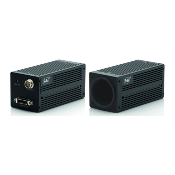
The AM-1600CL and AB-1600CL are 16-megapixel high resolution cameras for applications such as high density board inspection, flat panel display inspection, and so on. The AM-1600CL is a monochrome progressive scan CCD camera and the AB-1600CL is the equivalent Bayer mosaic progressive scan CCD camera. -
Page 6: Main Features
• 2.99 frames/second with full resolution in continuous operation • Variable partial scan is available with user-definable height and starting point • 2X binning in horizontal, vertical, or H & V directions (AM-1600CL only) • Programmable shutter from 3 lines (295.98µs) to 3248 lines (320.45ms) •... -
Page 7: Locations And Functions
AM-1600CL / AB-1600CL 4. Locations and Functions ④ ⑤ ⑥ P O WER / TR IG P O WER / TR IG DC IN / TR IG DC IN / TR IG ② ① D IGITAL I / O D IGITA I / O ⑥... -
Page 8: Pin Assignment
AM-1600CL / AB-1600CL 5. Pin Assignment 5.1. 12-pin Multi-connector (DC-IN/Trigger) Type: HR10A-10R-12PB-01 (Hirose) male. Use the part number HR10A-10P-12S for the cable side Pin no. Signal Remarks +12 V DC input XEEN out Trigger in Fig. 2 Hirose 12-pin connector DC+12V *1) Factory default is trigger via Camera Link. -
Page 9: Input And Output Circuits
AM-1600CL / AB-1600CL 5.3. Input and output circuits In the following schematic diagrams the input and output circuits for video and timing signals are shown. 5.3.1. Trigger input An external trigger input can be applied to pin 10 of 12-pin Hirose connector . - Page 10 AM-1600CL / AB-1600CL Port/Signal 8bitOutput 10bitOutput 12bitOutput Pin No. Port A0 Port A1 Port A2 Port A3 Port A4 Port A5 Port A6 Tx27 Port A7 Port B0 Port B1 Port B2 Port B3 Tx12 Port B4 Tx13 Port B5...
-
Page 11: Video Output Through Camera Link Connector
5.4. Video output through Camera Link connector AM-1600CL and AB-1600CL use a dual tap CCD sensor. The L channel video and R channel video are recomposed in the camera as one frame of the video. The odd pixel and even pixel on the raster frame is alternatively output through the camera link connector. -
Page 12: Functions And Operations
6.1. Before starting Important Note for operation of AM-1600CL and AB-1600CL AM-1600CL and AB-1600CLcameras use OS (Operating System) inside. Due to this, it is important to pay special attention when using the camera control tool. 1. The camera cannot communicate with the camera control tool until the LED turns to GREEN which is approx. -
Page 13: Electronic Shutter
6.2.5. Auto-detect LVAL-sync / async accumulation This function replaces the manual setting found in older JAI cameras. Whether accumulation is synchronous or asynchronous in relationship to LVAL depends on the timing of the trigger input. When trigger is received while FVAL is high (during readout), the camera works in LVAL- synchronous mode, preventing reset feed through in the video signal. -
Page 14: Starting Pixel - Bayer Color Mosaic
AM-1600CL / AB-1600CL External Trigger +/- 1 LVAL FVAL (1) In this period camera executes trigger at next LVAL (prevents feed-through noise) (2) Avoid trigger at FVAL transition (+/- LVAL period), as the function may randomly switch between “ next LVAL ” and “ immediate ”. -
Page 15: Binning Functions (Am-1600Cl Only)
Fig.10. Variable Partial scan 6.2.8. Binning Functions (AM-1600CL only) This function is only available on the AM-1600CL camera. The AM-1600CL incorporates 3 binning modes described below. Binning mode is a function where the signal charges from 2 adjacent (horizontal or/and vertical) pixels are added together and read out as one pixel. -
Page 16: Pre-Processing Functions (Overview)
6.3.1. Blemish Compensation (AM-1600CL only) AM-1600CL has a blemish compensation circuit. This function compensates for blemishes on the CCD sensor (typically pixels with extremely high response or extremely low response). This applies to Monochrome version only. Pixels that fulfill the blemish criteria can be compensated by using the adjacent pixel on the left side column as shown below. -
Page 17: Gain And Channel Balance
The AM-1600CL/AB-1600CL has a dual-tap readout architecture, with Left (L) and Right (R) channels. In order to achieve the same gain and black level for both channels, the AM-1600CL/AB- 1600CL has independent control for L channel and R channel gain and offset. -
Page 18: Sensor Layout And Timing
AM-1600CL / AB-1600CL 6.4. Sensor Layout and Timing 6.4.1. CCD Sensor Layout The CCD sensor layout with respect to pixels and lines used in the timing and video full frame read out is shown below. Fig. 12. CCD sensor layout... -
Page 19: Horizontal Timing
AM-1600CL / AB-1600CL 6.4.2. Horizontal Timing The LVAL period is shown for continuous mode. Continuous ( LVAL period) 1CLK=33.33 ns ( 30MHz) 2960 2468 LVAL int_XSUB int_XSG (Exposure) Effective pixels Buffer Buffer 2436 (CCD out) DATA out DVAL 2436 Fig. 13. Horizontal Timing... -
Page 20: Vertical Timing
AM-1600CL / AB-1600CL 6.4.3. Vertical Timing The FVAL period for continuous mode full scan is shown. Continuous mode ( Full frame mode) 3327L 3248L FVAL LVAL int_XSUB int_XSG (Exposure) Buffer Buffer Effective lines 3248L (CCD out) DATA out DVAL Fig. 14. Vertical Timing for full scan... -
Page 21: Partial Scan
AM-1600CL / AB-1600CL 6.4.4. Partial Scan Partial scan allows higher frame rates by reading out a smaller portion of the image. This is particularly useful when inspecting objects that do not fill the whole height of the image. Vertical timing... -
Page 22: Horizontal And Vertical Binning
Vertical binning combines charge from two adjacent rows, while horizontal binning combines charges from two adjacent columns, reducing the vertical or horizontal resolution to half and at the same time increasing frame rate. This function is available only for AM-1600CL. Important Note Vertical Binning cannot be used together with Partial Scanning. -
Page 23: Operation Modes
AM-1600CL / AB-1600CL Vertical Binning (Vertical Timing) Binning Continuous ( Full Frame period) 1665L 1624L FVAL LVAL int_XSUB int_XSG (Exposure) Buffer Buffer Effective lines 8L 2L 1624L (CCD out) DATA out DVAL Fig.18. Vertical Timing for vertical binning 6.5. Operation Modes This camera can operate in 3 primary modes. -
Page 24: Edge Pre-Select Trigger Mode (Eps)
AM-1600CL / AB-1600CL 6.5.2. Edge Pre-select Trigger Mode (EPS) In this mode, an external trigger pulse initiates the capture, and the exposure time (accumulation time) is defined by the selected shutter time . The resulting video signal will start to be read out after the shutter time. -
Page 25: Pulse Width Control Trigger Mode (Pwc)
AM-1600CL / AB-1600CL 6.5.3. Pulse Width Control Trigger Mode (PWC) In this mode the accumulation time is equal to the trigger pulse width. Here it is possible to have a long time exposure. For best image quality, the maximum recommended time is <6 frames (2 seconds), however, depending on your application, significantly longer exposure may still produce an acceptable signal-to-noise ratio, even without applying any external cooling. -
Page 26: Mode And Function Matrix
AM-1600CL / AB-1600CL 6.6. Mode and function matrix The following table shows which functions will work in the different modes for AM-1600CL / AB- 1600CL. Binning (Note*1) Shutter Accumulation Function Partial Trigger LVAL sync / Pre-set Programmable mode async Cont. -
Page 27: Configuring The Camera
7.2. Register based command control All configuration of the AM-1600CL / AB-1600CL camera is done via serial communication in the Camera Link connector. The camera can be set up from a PC running terminal emulator software, or using JAI's camera control software. - Page 28 AM-1600CL / AB-1600CL - 28 -...
- Page 29 AM-1600CL / AB-1600CL Gain & Offset Min. Max. Functions Command Note Value Value Relative Gain adjustment together 0x5FF RW :R0020@04A0#=00000XXX CH-A Relative Gain with OFF-SET adjustment for L ch. with Relative Gain adjustment together Offset Adjustment 0x5FF RW :R0020@04A4#=00000XXX CH-B...
- Page 30 AM-1600CL / AB-1600CL Exposure Min. Max. Functions Command Note Value Value Select Exposure control mode. Control Mode RW :R0010@0080#=0000000X Common 0: Preset mode control、1: Line step Selection mode Preset Mode Select Factory or User table RW :R0010@0084#=0000000X Table Type on Preset mode...
- Page 31 AM-1600CL / AB-1600CL LUT(continued) Y coordinate position of LUT first point. 131071 RW :R0020@0190#=000XXXXX Point 0 MUST be 0. 131071 RW :R0020@0194#=000XXXXX Point 1 Y coordinate position of LUT 2nd point. 131071 RW :R0020@0198#=000XXXXX Point 2 Y coordinate position of LUT 3rd point.
- Page 32 AM-1600CL / AB-1600CL Miscellaneous Min. Max. Functions Command Note Value Value Synchronize with the Internal Pulse Rest RW :R0010@0014#=00000000 Free-run ( Free Run Mode ) Control Mode Synchronized with the External Trigger RW :R0010@0014#=00000001 Trigger-Run Pulse ( Trigger Mode) RW :R0010@0024#=00000000 Trigger Mode Trigger mode.
-
Page 33: Trouble Shooting
AM-1600CL / AB-1600CL Parameter Min. Max. Functions Command Note Value Value Initial Loaded Page RW :R0010@0000#=0000000X 0 : Page 0, 1 : Page 1 RW :R0020@0040#=00000001 Execute Write "00000001" to execute " SAVE " Save RW :R0020@0044#=0000000X Page Select 0 : Page 0, 1 : Page 1... -
Page 34: Image Processing
AM-1600CL / AB-1600CL Image Processing Min. Max. Functions Command Note Value Value RW :R0010@02AC#=00000000 None No use of any functions RW :R0010@02AC#=00000001 Offset Correction Use only OFFSET correction Flat Field Function Used Gain and Offset RW :R0010@02AC#=00000002 Compensation Use Gain and OFFSET correction... -
Page 35: Camera Control Tool For Am-1600Cl / Ab-1600Cl
The Gain & Offset, General, Image Processing, and Utilities windows also contain a Communication window. The camera control software is for configuring and setting parameters of the AM-1600CL and AB- 1600CL. The interface is asynchronous serial communication through Camera Link, SerTFG and SerTC. -
Page 36: Start Up The Software
AM-1600CL / AB-1600CL Start to install the software 5. When the installation is completed. Click [CLOSE]. 8.3. Start up the software In order to communicate with the camera , it is necessary to select the appropriate port after starting up the software. -
Page 37: How To Connect The Camera
AM-1600CL / AB-1600CL The following start-up screen appears. Note: At this moment, communication is not initiated. 8.4. How to connect the camera Click [Refresh] to read available ports. - 37 -... -
Page 38: How To Disconnect The Camera
AM-1600CL / AB-1600CL Select the appropriate port ( in this case , COM3) Note: The available ports will differ depending on the setting of the Frame Graber board. Check the COM setting of Frame Graber board. Click [Connect] in order to connect the camera. - Page 39 AM-1600CL / AB-1600CL Note: [Refresh Tab] is independent on each control page. Accordingly, clicking on [Refresh tab] should be executed on each screen such as “General”, “Image Processing” and “Utilities”. Once it is executed, the communication between the control tool and camera is activated, and the indication of the control tool and the camera settings are synchronized.
-
Page 40: Functions
AM-1600CL / AB-1600CL 8.7.2 Functions 8.7.2(a) Gain & Offset Use these control to balance the left and right channels of the dual-tap output. Options are provided for manual or automatic balancing. Offset : This is used to adjust the video black level of the right channel to match the left channel. - Page 41 3. Click the balance [ON]. After completion, ON turns OFF automatically. Note: The Automatic balance adjustment for AM-1600CL and AB-1600CL uses L channel (A) as the reference level and adjusts R channel (B) so that it matches to the L channel level.
- Page 42 AM-1600CL / AB-1600CL [Offset Load] and [Gain Load] can load the Factory data or the user data independently. Four user indexes (0 to 3 )are available for each Offset and Gain. Use [Load Master Index] to select the same index for both Gain and Offset.
-
Page 43: B) General
AM-1600CL / AB-1600CL 8.7.2(b) General Note: In order to store the setting data on this page, click [Save RAM to Flash] on Gain & Offset page. The characteristics for LUT data can be stored on LUT setting page. Exposure: Set exposure time. - Page 44 AM-1600CL / AB-1600CL V-Reset Use this area to indicate whether or not the camera will be controlled by triggering. Free-run : Continuous operation by internal trigger Trigger-Run : Indicates that an external trigger will be used. Select EPS or PWC for Trigger-Run mode...
- Page 45 AM-1600CL / AB-1600CL LUT (AM-1600CL only) When a Gamma type of USER 1 to USER 6 is selected, a user-programmable Look-Up Table (LUT) appears. By using the LUT, the desired video output characteristics for the system can be created and stored.
- Page 46 Y boxes. Repeat with additional points until the desired response is defined. Example ↓ 5 Click [Save Graph] to save this setting for future recall. Horizontal-Binning & LPF (AM-1600CL only) Use this area to activate the horizontal binning function and LPF(Low Pass Filter). : No horizontal binning ■None ■Binning : Add two pixels in horizontal direction and read as one pixel...
-
Page 47: C) Image Processing
AM-1600CL / AB-1600CL Partial Scan Select [Enable] to initiate partial scanning, then enter the start line and the image height. Four settings (A to D) can be stored for future use. 8.7.2(C) Image Processing Note: In order to save the status of settings on this page, click [Save RAM to Flash] on the Gain &... - Page 48 AM-1600CL / AB-1600CL Blemish Compensation Calibration (AM-1600CL only) Initial blemish compensation calibration is performed at the factory and is not typically required. Factory data is loaded at startup and is then applied if the user has enabled Blemish Compensation. If subsequent calibration is performed, it must be done in the sequence of [Dark] first, then [Bright].
-
Page 49: D) Utilities
AM-1600CL / AB-1600CL Calibration must be performed in the sequence of [Dark] first, then [Bright]. Begin by clicking the [RUN] button in the [Dark] section. A pop-up window will instruct you to close the lens before continuing. Calibration will then proceed automatically untill completed. -
Page 50: Other Menu Selection
AM-1600CL / AB-1600CL ■ Test Pattern:The following three patterns are available. H.ramp V.ramp H & V ramp ■ Flash memory: There is a flash memory of two pages for saving data. The saved data can be loaded to the camera or verified. -
Page 51: External Appearance And Dimensions
9. External Appearance and Dimensions 4-M3 depth 5 P O WER / TR IG DC IN / TR IG DIGIT AL I / O 4-M3 depth 5 4-M3 depth 5 M42×1 4-M3 depth 5 Fig. 23. Outline. ( AM-1600CL-P/AB-1600CL-P) - 51 -... - Page 52 AM-1600CL / AB-1600CL 4-M3 depth 5 P O WER / TR IG DC IN / TR IG D IG ITAL I / O (34) 4-M3 depth 5 4-M3 depth 5 Nikon Mount Fig. 24. Outline ( AM-1600CL-F/AB-1600CL-F) - 52 -...
-
Page 53: Specifications
AM-1600CL / AB-1600CL 10. Specifications 10.1. Spectral response Fig. 25. Spectral response for AM-1600CL Fig.26. Spectral response for AB-1600CL - 53 -... -
Page 54: Specification Table
AM-1600CL / AB-1600CL 10.2. Specification table Item AM-1600CL AB-1600CL Scanning System Progressive scan Full 4872 (H) x 3248 (V) 2.99 fps (dual tap) 1/2 4872 (H) x 1624 (V) 6.3 fps ( Note ) Frame Rate 1/4 4872 (H) x 814 (V) 11.5 fps ( Note) - Page 55 AM-1600CL / AB-1600CL Item AM-1600CL AB-1600CL Shock 70 G CE (EN61000-6-3,EN61000-6-3), FCC Part15 Class B、RoHS Regulatory Noise Immunity ( EN61000-6-2 ) Power DC +12V ± 10% 5.8 W ( typical , Continuous , Lens Cap on) Power consumption (W) 7.8W ( Max. , 800 partial, Light in ) Universal P Mount ( M42 x 1.0 ) or...
-
Page 56: Appendix
AM-1600CL / AB-1600CL 11. Appendix 10.3. Precautions Personnel not trained in dealing with similar electronic devices should not service this camera. The camera contains components sensitive to electrostatic discharge. The handling of these devices should follow the requirements of electrostatic sensitive components. -
Page 57: References
AM-1600CL / AB-1600CL 10.5. References 1. This manual for AM-1600CL / AB-1600CL can be downloaded from www.jai.com 2. Datasheet for AM-1600CL / AB-1600CL can be downloaded from www.jai.com 3. Camera control software can be downloaded from www.jai.com 4. Specifications for the CCD sensor Kodak KAI-16000-AXA and KAI-16000-CXA can be found on www.jai.com... - Page 58 AM-1600CL / AB-1600CL Index Bayer mosaic color, - 6 -, - 12 - Preset Shutter, - 54 - Binning mode, - 15 - Programmable exposure, - 6 - Bit Allocation, - 12 - Progressive scan, - 5 -, - 6 -, - 12 -...
-
Page 59: User's Record
Company and product names mentioned in this manual are trademarks or registered trademarks of their respective owners. JAI A-S cannot be held responsible for any technical or typographical errors and reserves the right to make changes to products and documentation without prior notification. - Page 60 AM-1600CL / AB-1600CL - 60 -...
- Page 61 AM-1600CL / AB-1600CL - 61 -...
Need help?
Do you have a question about the AM-1600CL and is the answer not in the manual?
Questions and answers