JAI Sweep Series User Manual
With coaxpress interface
Hide thumbs
Also See for Sweep Series:
- User manual (133 pages) ,
- User manual (119 pages) ,
- User manual (114 pages)
Table of Contents
Advertisement
Quick Links
User Manual
Sweep Series - CoaXPress Interface
SW-2005TL-CXP
SW-2005M-CXP
Thank you for purchasing this product.
Be sure to read this documentation before use.
This documentation includes important safety precautions and instructions on how to operate the unit. Be sure to read this documentation to ensure
proper operation.
The contents of this documentation are subject to change without notice for the purpose of improvement.
© 2024 JAI
Digital CMOS Progressive Line Scan Camera (Trilinear and Monochrome)
Document Version: Tentative
Date: 2024-09-26
Advertisement
Table of Contents

Related Manuals for JAI Sweep Series


Summary of Contents for JAI Sweep Series
- Page 1 User Manual Sweep Series - CoaXPress Interface SW-2005TL-CXP SW-2005M-CXP Digital CMOS Progressive Line Scan Camera (Trilinear and Monochrome) Document Version: Tentative Date: 2024-09-26 Thank you for purchasing this product. Be sure to read this documentation before use. This documentation includes important safety precautions and instructions on how to operate the unit. Be sure to read this documentation to ensure proper operation.
-
Page 2: Table Of Contents
User Manual (Tentative) - Table of Contents SW-2005TL-CXP | SW-2005M-CXP Table of Contents Table of Contents About Technical Note Notice/Warranty Notice Warranty Certifications CE Compliance Warning China RoHS Usage Precautions Notes on Cable Configurations Notes on Attaching the Lens Phenomena Specific to CMOS Image Sensors Notes on Exportation Features Package Contents, Accessories... - Page 3 User Manual (Tentative) - Table of Contents SW-2005TL-CXP | SW-2005M-CXP ④ CXP Frame Grabber Board ⑤ DC IN / Trigger IN Connection Cable ⑥ AC adapter (Power Supply, If Necessary) Step 2: Verify Camera Operation Step 3: Verify the Connection between the Camera and PC Step 4: Configure Trigger, Exposure, and Line Rate Settings Control via External Triggers with the Specified Exposure Time Control via External Triggers without Specifying the ExposureTime...
- Page 4 User Manual (Tentative) - Table of Contents SW-2005TL-CXP | SW-2005M-CXP Gamma Function LUT (Lookup Table) Color Space Conversion (ColorTransformationControl) GPIO (Digital Input/Output Settings) ExposureActive Signal Counter and Timer Control Connecting Rotary Encoders EncoderDivider Trigger Option EdgeDetection Trigger Option Rotation Direction Event Control Function Logic Block Control Pulse Generator...
-
Page 5: About Technical Note
About Technical Note Some additional technical information is provided on the JAI website as Technical Notes. In this manual, if a technical note is available for a particular topic, the above icon is shown. Please refer to the following URL for Technical notes. -
Page 6: Notice/Warranty
The material contained in this manual consists of information that is proprietary to JAI Ltd., Japan, and may only be used by the purchasers of the product. JAI Ltd., Japan makes no warranty for the use of its product and assumes no responsibility for any errors which may appear or for damages resulting from the use of the information contained herein. -
Page 7: Warning
상 호: JAI Ltd. Japan 기자재명칭: Industrial Camera 기자재명칭: Industrial Camera 모 델 명: SW-2005TL-CXP 모 델 명: SW-2005M-CXP 제조자 및 제조국가: JAI Ltd., Japan / JAPAN 제조자 및 제조국가: JAI Ltd., Japan / JAPAN 제조년월은 제품상자의 라벨을 참조하십시오. - 7 -... -
Page 8: China Rohs
User Manual (Tentative) - Notice/Warranty SW-2005TL-CXP | SW-2005M-CXP China RoHS The following statement is related to the regulation on “Measures for the Administration of the Control of Pollution by Electronic Information Products “, known as “China RoHS“. The table shows contained Hazardous Substances in this camera. -
Page 9: Usage Precautions
User Manual (Tentative) - Usage Precautions SW-2005TL-CXP | SW-2005M-CXP Usage Precautions Notes on Cable Configurations The presence of lighting equipment and television receivers nearby may result in video noise. In such cases, change the cable configurations or placement. Notes on Attaching the Lens How to Clean a Sensor Avoiding Dust Particles When attaching the lens to the camera, stray dust and other particles may adhere to the sensor surface and... -
Page 10: Notes On Exportation
User Manual (Tentative) - Usage Precautions SW-2005TL-CXP | SW-2005M-CXP ambient temperature, camera settings (e.g., high sensitivity and long exposure), and other factors, be sure to operate within the camera’s specified operating environment. Notes on Exportation When exporting this product, please follow the export regulations of your country or region. - 10 -... -
Page 11: Features
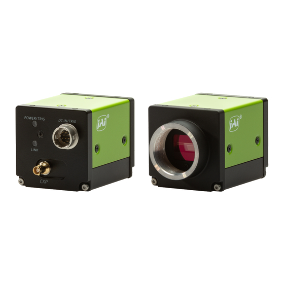
User Manual (Tentative) - Features SW-2005TL-CXP | SW-2005M-CXP Features This camera is a linescan camera using trilinear (RGB) and monochrome CMOS line sensors. It has a small (44mm × 44mm × 54mm), lightweight (TBD g) design with a CoaXPress v2.0, CXP-6 interface. Model Name Image Sensor Effective Pixels... -
Page 12: Parts Identification
User Manual (Tentative) - Parts Identification SW-2005TL-CXP | SW-2005M-CXP Parts Identification Note: See "Dimensions" for external view of the entire camera. Lens Mount (C-Mount) Mount a C-mount lens here. Note: Before mounting a lens, be sure to refer to ① Lens and confirm the precautions for attaching a lens and the supported lens types. -
Page 13: Dc In/Trig Connector (12-Pin Round)
User Manual (Tentative) - Parts Identification SW-2005TL-CXP | SW-2005M-CXP DC IN/TRIG Connector (12-Pin Round) Related Setting Items: DigitalIOControl Connect the cable for a power supply or for DC IN / trigger IN here. PN: HR-10A-10R-12PB (71) Pin No. Input/Output Signal Description Power In DC In... -
Page 14: Leds
User Manual (Tentative) - Parts Identification SW-2005TL-CXP | SW-2005M-CXP Note: You can check the current CXP version in CxpVersion Used [TransportLayerControl]. If CxpVersionUsed is CXP 1.1, you cannot use the CXP12 link configurations. Even if you are using a CoaXPress frame grabber board that supports CXP 2.0, if CxpVersionUsed is CXP 1.1, you may need to make settings on the frame grabber board side. -
Page 15: Mounting Holes
User Manual (Tentative) - Parts Identification SW-2005TL-CXP | SW-2005M-CXP Light Status When using PoCXP: Detecting link. Alternating between green and amber - rapid Note: Blinks for 1 second even when detected immediately. When not using PoCXP: Detecting link. Blinking amber - rapid Note: Blinks for 1 second even when detected immediately. -
Page 16: Preparation
Read this section to learn how the camera connects to devices and accessories. The preparation process is described below. Note: This camera does not support eBUS Player for JAI. Step 1: Connect Devices Connect the lens, cables, AC adapter, computer, and other devices. -
Page 17: Step 1: Connect Devices
User Manual (Tentative) - Preparation SW-2005TL-CXP | SW-2005M-CXP Step 1: Connect Devices ① Lens ② Mounting ③ CXP cable ④ CXP Frame Grabber Board ⑤ DC IN / Trigger IN Connection Cable ⑥ AC adapter (Power Supply, If Necessary) ① Lens C-mount lenses with lens mount protrusions of 9 mm or less can be attached. -
Page 18: ② Mounting
User Manual (Tentative) - Preparation SW-2005TL-CXP | SW-2005M-CXP ② Mounting When mounting the camera directly to a device, use screws that match the mounting holes on the camera. For more information on the mounting holes, see "Mounting Holes ". Caution: For heavy lenses, be sure to support the lens itself. -
Page 19: Step 2: Verify Camera Operation
Use the appropriate tool for the CoaXPress frame grabber board to be used to set up the camera and display captured images. Refer to the operation manual of the tool to be used for the operation method. Note: This camera does not support eBUS Player for JAI. - 19 -... -
Page 20: Step 4: Configure Trigger, Exposure, And Line Rate Settings
User Manual (Tentative) - Preparation SW-2005TL-CXP | SW-2005M-CXP Step 4: Configure Trigger, Exposure, and Line Rate Settings Related Setting Items: AcquisitionControl This section describes five scenarios for controlling the trigger, exposure, and line rate. Note: This section is intended to explain the basic relationship between the trigger, exposure, and line rate. Trigger Exposure Setting Example... -
Page 21: Control Via External Triggers With The Specified Exposure Time
User Manual (Tentative) - Preparation SW-2005TL-CXP | SW-2005M-CXP Control via External Triggers with the Specified Exposure Time In the example below, TriggerSelector is set to LineStart. Notes: When using external triggers, the line rate is determined by the trigger period. The ExposureTime value cannot be longer than the trigger period. -
Page 22: Control Via External Triggers Without Specifying The Exposuretime
User Manual (Tentative) - Preparation SW-2005TL-CXP | SW-2005M-CXP Control via External Triggers without Specifying the ExposureTime In the example below, TriggerSelector is set to LineStart. Notes: When using external triggers, the line rate is determined by the trigger period. The exposure is performed with an exposure time calculated from 1 / (line rate). Item Setting Trigger Mode... -
Page 23: Control Via External Triggers With Exposure Time Controlled By The Pulse Width Of The Trigger Input Signal
User Manual (Tentative) - Preparation SW-2005TL-CXP | SW-2005M-CXP Control via External Triggers with Exposure Time Controlled by the Pulse Width of the Trigger Input Signal In the example below, TriggerSelector is set to LineStart. Notes: When using external triggers, the line rate is determined by the trigger period. Item Setting Trigger Mode... -
Page 24: Control Without External Triggers With The Specified Exposure Time
User Manual (Tentative) - Preparation SW-2005TL-CXP | SW-2005M-CXP Control without External Triggers with the Specified Exposure Time Notes: ExposureTime can be set up to 1 line cycle to match the speed of the object or to lengthen the accumulation time to increase sensitivity. The ExposureTime value cannot be longer than the line period. -
Page 25: Step 5: Adjust The Image Quality
User Manual (Tentative) - Preparation SW-2005TL-CXP | SW-2005M-CXP Step 5: Adjust the Image Quality Display the camera image and adjust the image quality. DSNU Correction (Pixel Black Correct) Related Setting Items: Correction DSNU (dark signal non-uniformity) is a variation between pixels in the dark areas generated by the sensor. If the line rate is slowed or a long exposure time is set, the dark current in the sensor may change and the state of the DSNU may change. -
Page 26: Prnu Correction (Pixel Gain Correct)
User Manual (Tentative) - Preparation SW-2005TL-CXP | SW-2005M-CXP PRNU Correction (Pixel Gain Correct) Related Setting Items: Correction PRNU (photo response non-uniformity) is a variation between pixels generated by the sensor under bright conditions. If the line rate is slowed or a long exposure time is set, the dark current in the sensor may change and the state of the PRNU may change. - Page 27 User Manual (Tentative) - Preparation SW-2005TL-CXP | SW-2005M-CXP 2. Specify the setting (User1, User2, User3, or User Area) to save the gain correction value in PixelGainCorrectionMode (Correction). For detailed information on each correction setting, see the "PRNU Correction Modes (PixelGainCorrectionMode)" section. Note: Default saves the correction data set at the factory.
-
Page 28: Adjust The Gain
User Manual (Tentative) - Preparation SW-2005TL-CXP | SW-2005M-CXP Adjust the Gain Related Setting Items: AnalogControl Note: For details on gain control, see “Gain Control” in the Main Functions chapter. Manual Adjustment Monochrome Model: 1. If you want to disable the camera's internal fixed gain (= InGain) and only enable the user-set gain, set InGainBypassMode to On (default = Off). -
Page 29: Adjust The White Balance
User Manual (Tentative) - Preparation SW-2005TL-CXP | SW-2005M-CXP 3. Configure AGCReference to set the convergence level. 4. Set GainAuto to Once. 5. The Gain value is automatically adjusted. After the adjustment, GainAuto returns to Off. 6. The adjustment status can be checked in AGCOnceStatus. Adjust the White Balance Related Setting Items: AnalogControl... - Page 30 User Manual (Tentative) - Preparation SW-2005TL-CXP | SW-2005M-CXP 2. If necessary, use BalanceWhiteAutoWidth and BalanceWhiteAutoOffsetX to configure the white balance adjustment area. 3. Set BalanceWhiteAuto to Once or OnceUserAreaBe. For more information, see "Automatic Adjustment Modes". Caution: The BalanceWhiteAutoWidth and BalanceWhiteAutoOffsetX settings apply only to the Once option.
-
Page 31: Adjust The Black Level
User Manual (Tentative) - Preparation SW-2005TL-CXP | SW-2005M-CXP Adjust the Black Level Related Setting Items: AnalogControl 1. Select the black level you want to configure in BlackLevelSelector. Monochrome model: All (Master black) only Color model: All (Master black), Red, Blue 2. -
Page 32: To Save User Settings
User Manual (Tentative) - Preparation SW-2005TL-CXP | SW-2005M-CXP To Save User Settings 1. Stop image acquisition. 2. Expand UserSetControl and select the save destination (UserSet1 to UserSet3) in UserSetSelector. Note: The factory default setting values are stored in Default and cannot be overwritten. Caution: Settings can only be saved when image acquisition on the camera is stopped. -
Page 33: Main Functions
User Manual (Tentative) - Main Functions SW-2005TL-CXP | SW-2005M-CXP Main Functions This chapter describes the camera's main functions. ROI (Regional Scanning Function) Related Setting Items: ImageFormatControl The ROI (region of interest) function allows you to output images by specifying the area to scan. ROI Settings Specify the area to scan by specifying the Width and Horizontal offset value (ImageFormatControl). -
Page 34: Binning Function
Note: This camera supports Horizontal x2 digital binning on the FPGA. Setting Pixel Size, Resolution Image Example 1 (Off) 2 (On) (Sum Mode) Note: Refer to JAI's blog "Using pixel binning to increase image quality under low light conditions" on how to use the Binning function. - 34 -... -
Page 35: Pixel Format
User Manual (Tentative) - Main Functions SW-2005TL-CXP | SW-2005M-CXP Pixel Format Related Setting Items: ImageFormatControl Selectable PixelFormat is as follows. Color model RGB8 (Default) , RGB10, RGB12 Monochrome model Mono8 (Default) , Mono10, Mono12 Acquisition Control Related Setting Items: AcquisitionControl AcquisitionStart / AcquisitionStop Start image acquisitions (AcquisitionStart) and end image acquisitions (AcquisitionStop). -
Page 36: Trigger Control
User Manual (Tentative) - Main Functions SW-2005TL-CXP | SW-2005M-CXP Trigger Control Related Setting Items: AcquisitionControl The camera allows the following controls to be performed via external trigger signals. Note: When TriggerMode is On, the camera first receives the AcquisitionStart command (ImageFormatControl), the Acquisition trigger signal, and then outputs images. -
Page 37: Trigger Delay Based On Encoder Input
User Manual (Tentative) - Main Functions SW-2005TL-CXP | SW-2005M-CXP Trigger Delay Based on Encoder Input The TriggerDelayLine function allows you to set the number of lines between the AcquisitionStart trigger input and the time when image data is output to the host. This function is useful when you want to delay the time between receiving a trigger and outputting image data to the host, for example, when the object detection sensor and the line scan camera cannot be installed in the same location. -
Page 38: Exposure Mode
User Manual (Tentative) - Main Functions SW-2005TL-CXP | SW-2005M-CXP Exposure Mode Related Setting Items: AcquisitionControl The following exposure modes are available on the camera. Exposure Description Examples Mode Control via External Triggers without Specifying the ExposureTime Exposure control is not performed (free-running operation). - Page 39 User Manual (Tentative) - Main Functions SW-2005TL-CXP | SW-2005M-CXP ExposureModeOption Specifies whether to prioritize exposure time (PrioritizeExposureTime) or line rate (PrioritizeLineRate) when controlling line rate and exposure. ExposureModeOption Description The maximum AcquisitionLineRate value is limited by the line rate value calculated from the current ExposureTime setting.
-
Page 40: Exposure Time
User Manual (Tentative) - Main Functions SW-2005TL-CXP | SW-2005M-CXP Exposure Time The ExposureTime function allows you to set the exposure to a preconfigured accumulation time. The minimum ExposureTime setting is 0.11 μs (step 0.01), and the maximum Exposure setting depends on other settings (e.g., PixelFormat). -
Page 41: Gain Control
User Manual (Tentative) - Main Functions SW-2005TL-CXP | SW-2005M-CXP Gain Control Related Setting Items: AnalogControl Gain control can be performed in the following two modes on this camera. Note: For details on how to configure the settings, see “Adjust the Gain”. -
Page 42: Gamma Function
Description Gamma 0.45, 0.5, 0.55, 0.6, 0.65, 0.75, 0.8, 0.9, 1.0 Select the gamma correction value. JAI LUT Mode Gamma Use gamma. Note: You can use the LUT function to configure a curve with more detailed points. For details, see “LUT... -
Page 43: Lut (Lookup Table)
You can specify the output curve using 257 setting points (indexes). To use the LUT function Configure the settings as follows. Setting Value / Item Description Selectable Range JAI LUT Use LUT. Mode Select the LUT channel to control. Red, Green, Blue Selector Note: Color model only Select the LUT index to configure. -
Page 44: Color Space Conversion (Colortransformationcontrol)
User Manual (Tentative) - Main Functions SW-2005TL-CXP | SW-2005M-CXP Color Space Conversion (ColorTransformationControl) Related Setting Items: Color Transformation Control This camera allows you to convert the standard color space (RGB) that is used to produce colors into other color spaces. Note: This function is only supported on the color model. -
Page 45: Gpio (Digital Input/Output Settings)
User Manual (Tentative) - Main Functions SW-2005TL-CXP | SW-2005M-CXP GPIO (Digital Input/Output Settings) Related Setting Items: DigitalIOControl The camera is equipped with GPIO (general-purpose input/output) functions for generating and using combinations of triggers and other necessary signals within the camera and of signals output from the camera to the system such as those used for lighting equipment control. -
Page 46: Exposureactive Signal
User Manual (Tentative) - Main Functions SW-2005TL-CXP | SW-2005M-CXP ExposureActive Signal Perform external output for the timing at which video is accumulated to the sensor. The signal is output to the DC IN / TRIG IN connector (12-pin round). ExposureActiveSource (Color model only) When LineSource is set to ExposureActive, the timing of the ExposureActive signal output will be different for each RGB channel due to the difference in RGB exposure time. - Page 47 User Manual (Tentative) - Main Functions SW-2005TL-CXP | SW-2005M-CXP How to Configure 1. Select the counter you want to use from CounterSelector. 2. Enable the counter by selecting the event source in ConterEventSource (Defaut = Off). 3. CounterEventActivation displays the timing for counting for the selected counter. 4.
-
Page 48: Connecting Rotary Encoders
Line Rate Does NOT Match the Belt Speed Line Rate Matches the Belt Speed Note: JAI cameras only support 2 Phase (Phase A and Phase B) incremental encoders. How to Configure 1. Connect the two signals (Phase A and Phase B) from the rotary encoder to the camera's inputs (EncoderSourceA and EncoderSourceB). - Page 49 User Manual (Tentative) - Main Functions SW-2005TL-CXP | SW-2005M-CXP Note: With this setting, input pulses are generated on the rising edge of the Phase A signal. EncoderDetection: Specify the number of edges to pass between each encoder trigger signal. The number of edges to pass is specified by EncoderEdgeDectionPassCount. For more information, see "EdgeDetection Trigger Option".
-
Page 50: Encoderdivider Trigger Option
User Manual (Tentative) - Main Functions SW-2005TL-CXP | SW-2005M-CXP When set to 0 (Default) , the trigger output period is calculated using only the encoder input period. When set to anything other than 0, the trigger output period is calculated using the encoder input period and this setting. -
Page 51: Edgedetection Trigger Option
User Manual (Tentative) - Main Functions SW-2005TL-CXP | SW-2005M-CXP EncoderDivider Examples EncoderDivider PhaseA Input Number of Triggers Timing Chart Setting Pulse (Output Pulse No.) 2 (= 65536/32768) 32768 The camera generates "two" triggers per a PhaseA input pulse signal. 1 (= 65536/65536) 65536 The camera generates "one"... -
Page 52: Rotation Direction
User Manual (Tentative) - Main Functions SW-2005TL-CXP | SW-2005M-CXP EdgeDetection Examples Edge Dection Pass Count Description Timing Chart Setting The camera generates "one" trigger per an input pulse (Default) signal. The camera generates "one" trigger per "two" input pulse signals. The camera generates "one"... -
Page 53: Event Control Function
User Manual (Tentative) - Main Functions SW-2005TL-CXP | SW-2005M-CXP Event Control Function Related Setting Items: EventControl The Event Control function is a function that outputs a signal change point inside the camera as information indicative of an event occurrence (event message). Flow from Detecting an Event to Sending an Event Message How to Configure 1. -
Page 54: Logic Block Control
User Manual (Tentative) - Main Functions SW-2005TL-CXP | SW-2005M-CXP Logic Block Control Related Topic: Logic Block Control This camera supports the Logic Block Control function. A Logic Block is a combinational logic element that conditions various input signal sources by determining true/false and generates output signals accordingly. This camera supports up to 4 Logic Blocks, and each block has two input sources. -
Page 55: Pulse Generator
User Manual (Tentative) - Main Functions SW-2005TL-CXP | SW-2005M-CXP Pulse Generator Related Setting Items: PulseGenerator Tips for using the Pulse Generator By using this function, any signal can be generated inside the camera. The following is an example of signal generation. Settings PulseGeneratorStartPoint = 2 PulseGeneratorEndPoint = 6... -
Page 56: Shading Correction
User Manual (Tentative) - Main Functions SW-2005TL-CXP | SW-2005M-CXP Shading Correction Related Setting Items: Shading The ShadingCorrection function corrects non-uniformity (i.e., shading) in the amount of light generated by the lens and lighting equipment. This camera supports the following shading correction modes. FlatShading, FlatShadingUserAreaBE ColorShading*, ColorShadingUserArera BE* R-channel and B-channel properties are adjusted by... -
Page 57: How To Configure The Shading Correction Function
User Manual (Tentative) - Main Functions SW-2005TL-CXP | SW-2005M-CXP Shading Correction Blocks The camera makes adjustments in blocks (1 block = 2 pixels). The block Index number (ShadingDataIndex) can be used to view and change the settings per block (ShadingData). For more information, see "How to Configure the Shading Correction Function". - Page 58 User Manual (Tentative) - Main Functions SW-2005TL-CXP | SW-2005M-CXP 5. Once the shading correction is successfully completed, the shading correction values are automatically saved to the area specified in ShadingMode. Also, the calibration result "Succeeded" is displayed in ShadingDetectResult. 6. If the image is too bright or too dark, the camera will operate differently depending on the selected Shading Correction Mode.
-
Page 59: User Area Be "Best Effort" Correction Example
User Manual (Tentative) - Main Functions SW-2005TL-CXP | SW-2005M-CXP User Area BE "Best Effort" Correction Example In this example, the blue cylinder on the conveyor belt is the object you want to correct shading. However, because a yellow object with a high brightness level is also included in the image, FlatShading or ColorShading modes, which calculate the correction value from the entire image, may not be able to correct shading properly. -
Page 60: Chromatic Aberration Correction
User Manual (Tentative) - Main Functions SW-2005TL-CXP | SW-2005M-CXP We recommend performing DSNU and PRNU calibration again whenever the line rate setting is changed significantly. A single correction data entry can be saved on the camera for each user. When calibration is performed, the correction data is saved to the non-volatile ROM at the same time. - Page 61 User Manual (Tentative) - Main Functions SW-2005TL-CXP | SW-2005M-CXP formula. Custom: Modify each correction point as desired. 3. Configure the correction settings, which vary depending on the selected correction method. Simple Interpolation: Select R Channel from ChromaticAberrationCorrectionSelecter and set the correction value in ChromaticAberrationCorrection. Linear Spline Interpolation: Configure the correction settings as follows.
- Page 62 User Manual (Tentative) - Main Functions SW-2005TL-CXP | SW-2005M-CXP 5. Execute ChromaticAberrationCorrectionSave to save the settings. The saved settings are for the area (Lens1 ~ 3) selected in ChromaticAberrationCorrectionMode. Note: When the selected correction method is Linear Spline Interpolation or Custom, the correction value of each index will be calculated using the following formula.
-
Page 63: Tilt View Correction
User Manual (Tentative) - Main Functions SW-2005TL-CXP | SW-2005M-CXP Tilt View Correction Related Setting Items: Correction This function corrects the trapezoidal distortion that occurs when a trilinear camera is placed at an off-axis viewing angle. The trapezoidal distortion is caused due to the fact that the optical path from object surface to the closest color channel on the sensor is shorter than the other two color channels. -
Page 64: Noise Reduction Filter Functions
Select the target to apply the filter from Red, Green, Blue, and set the Median Filter Mode. When set to On, this function is enabled. (Default = Off). Noise Reduction: Apply the noise filter using JAI's own algorithm. Set the noise reduction intensity in 4 levels. Level1 = weak, Level4 = strong. -
Page 65: Spatial Compensation
User Manual (Tentative) - Main Functions SW-2005TL-CXP | SW-2005M-CXP Spatial Compensation Related Setting Items: SpatialControl Note: This function is supported only on the color model. This function corrects the spatial pixel differences individually for the R, G, and B lines captured by the trilinear line sensor. - Page 66 User Manual (Tentative) - Main Functions SW-2005TL-CXP | SW-2005M-CXP Note: The object direction signal is used to obtain the direction of the imaging subject. The direction signal from the rotary encoder, the I/O signal input of the camera, or the high/low control signal from the software can be used as the object direction signal.
-
Page 67: Setting List (Feature Properties)
This camera complies with GenICam. Each setting item name conforms to GenICam SFNC (Standard Features Naming Convention). (There are some JAI-specific setting items). Each setting item is an integer type (IInteger), a real type (IFloat), an element enumeration type (IEnumeration), a character string (IString), a logical type (IBoolean), and a category type (ICategory) or a command type (ICommand) for executing the function. -
Page 68: Devicecontrol
Display/configure information related to the device. DeviceControl Item Setting Range Default Description DeviceScanType 1: Line Scan Display the device's scan type. DeviceVendorName “JAI Corporation” Display the manufacturer name. DeviceManufacturerInfo See the possibilities Display manufacturer information. DeviceVersion Display the software version. DeviceFirmwareVersion Display the firmware version. - Page 69 User Manual (Tentative) - Setting List (Feature Properties) SW-2005TL-CXP | SW-2005M-CXP DeviceControl Item Setting Range Default Description Display the minor version number of the DeviceTLVersionMinor Transport Layer type. Display the sub minor version number of the DeviceTLVersionSubMinor Transport Layer type. Off: No CXP bandwidth limit;...
-
Page 70: Transportlayercontrol
User Manual (Tentative) - Setting List (Feature Properties) SW-2005TL-CXP | SW-2005M-CXP TransportLayerControl Display information on transport layer control. Setting Transport Layer Control Item Default Description Range 48 ~ PayloadSize (bytes) Display the payload size. (unit: bytes) 67109240 0: Geometry_1X_ The method of transferring images from the device at one DeviceTapGeometry 1Y ( ... -
Page 71: Imageformatcontrol
User Manual (Tentative) - Setting List (Feature Properties) SW-2005TL-CXP | SW-2005M-CXP ImageFormatControl Configure image format settings. Image Format Control Setting Range Default Description Item SW-2005M-CXP: 2048 SensorWidth Display the maximum image width. SW-2005TL-CXP: 2048 SW-2005M-CXP: 2048 (1024) WidthMax SW-2005TL-CXP: 2048 (1024) Display the maximum image width. -
Page 72: Acquisitioncontrol
User Manual (Tentative) - Setting List (Feature Properties) SW-2005TL-CXP | SW-2005M-CXP Image Format Control Setting Range Default Description Item Color Model: RGB8: Bpp24 (Default) RGB10: Bpp48 RGB12: Bpp48 PixelSize Display the total pixel size of the output image in bits. Monochrome Model: Mono8: Bpp8 (Default) Mono10: Bpp16... - Page 73 User Manual (Tentative) - Setting List (Feature Properties) SW-2005TL-CXP | SW-2005M-CXP Acquisition Control Setting Range Default Description Item 7-10: PulseGenerator0-3 11-14: UserOutput0-3 19: Software 23: Line4 TTL In1 (Default) TriggerSource 24: Line5 Opt In1 Select the trigger signal source. 26:Line7 Cxp In 33: Line14 TTL In4 36-39: Logic Block0-3 40: EncoderTrigger...
-
Page 74: Analogcontrol
User Manual (Tentative) - Setting List (Feature Properties) SW-2005TL-CXP | SW-2005M-CXP Acquisition Control Setting Range Default Description Item ExposureModeOption 0: PrioritizeExposureTime Specifies whether to prioritize exposure time (PrioritizeExposureTime) or (Default) Related Topic: line rate (PrioritizeLineRate) when controlling line rate and exposure. 1: PrioritizeLineRate Exposure Mode AnalogControl... - Page 75 Gamma 0.65, 0.75, 0.8, 0.9, 1.0 Function 0: Off (Default) LUT Mode 1: Gamma Select the JAI LUT mode. 2: LUT GainAuto Enable/disable gain auto adjustment. Once automatically changes to 0: Off (Default) Off when the signal level converges once.
-
Page 76: Lut Control
User Manual (Tentative) - Setting List (Feature Properties) SW-2005TL-CXP | SW-2005M-CXP Analog Control Item Setting Range Default Description GainAutoWidth The same value as Width [ImageFormatControl]. GainAutoOffsetX The same value as OffsetX [ImageFormatControl]. AGCReference 30 ~ 95 % Set the target level for GainAuto in percentage. 0: Idle (Default) 1: Processing 3: Succeeded... -
Page 77: Color Transformation Control
User Manual (Tentative) - Setting List (Feature Properties) SW-2005TL-CXP | SW-2005M-CXP Color Transformation Control Related Topic: Color Space Conversion (ColorTransformationControl) Configure LUT settings. Note: Color model only Color Transformation Setting Range Default Description Control Item 0: RGB (Default) ColorTransformationMode Set the output image format. 2: XYZ 0: Off (Default) 1: sRGB... -
Page 78: Digitaliocontrol
User Manual (Tentative) - Setting List (Feature Properties) SW-2005TL-CXP | SW-2005M-CXP DigitalIOControl Related Topic: GPIO (Digital Input/Output Settings) Configure settings for digital input/output. Digital IO Control Item Setting Range Default Description 20: Line1 TTL Out1 (Default) 23: Line4 TTL In1 24: Line5 Opt In1 LineSelector Select the input/ output to configure. - Page 79 User Manual (Tentative) - Setting List (Feature Properties) SW-2005TL-CXP | SW-2005M-CXP Digital IO Control Item Setting Range Default Description 1: AcquisitionActive 4: ExposureActive 6: LVAL 7-10: PulseGenerator0-3 Select the line source signal for the item selected in Line Selector. 11-14: UserOutput0-3 23: Line4 TTL In1 The following is fixed to "-": (Default)
-
Page 80: Counter And Timer Control
User Manual (Tentative) - Setting List (Feature Properties) SW-2005TL-CXP | SW-2005M-CXP Counter and Timer Control Related Topic: Counter and Timer Control Configure counter settings. (This camera only supports counter functions.) Counter and Timer Control Setting Range Default Description Item 0: Counter0 (Default) CounterSelector 1: Counter1 Select the counter. -
Page 81: Encodercontrol
User Manual (Tentative) - Setting List (Feature Properties) SW-2005TL-CXP | SW-2005M-CXP EncoderControl Related Topic: Connecting Rotary Encoders Configure settings for encoder control. Setting Encoder Control Item Default Description Range 0: Off (Default) 23: Line4 TTL In1 EncoderSourceA Select where to input the signal from the rotary encoder. 24: Line5 Opt In1 EncoderSourceB 33: Line14 TTL... - Page 82 User Manual (Tentative) - Setting List (Feature Properties) SW-2005TL-CXP | SW-2005M-CXP Setting Encoder Control Item Default Description Range 10 ~ Set the strobe length of the Trigger signal generated from the rotary encoder by EncoderStrobe (ns) 2550, the number of cycles. step: 10 0: none (Default) 1: 2 pulses...
-
Page 83: Logic Block Control
User Manual (Tentative) - Setting List (Feature Properties) SW-2005TL-CXP | SW-2005M-CXP Logic Block Control Related Topic: Logic Block Control Configure Logic Block settings. Logic Block Control Item Setting Range Default Description 0: Logic Block 0 (Default) 1: Logic Block 1 Logic Block Selector Specifies the Logic Block to configure. -
Page 84: Eventcontrol
User Manual (Tentative) - Setting List (Feature Properties) SW-2005TL-CXP | SW-2005M-CXP EventControl Related Topic: Event Control Function Configure event control settings. Note: Items with "*" are only supported on the color model. Setting Event Control Item Default Description Range 0: AcquisitionStart (Default) 1: AcquisitionEnd 4: ExposureRedStart*... - Page 85 User Manual (Tentative) - Setting List (Feature Properties) SW-2005TL-CXP | SW-2005M-CXP Setting Event Control Item Default Description Range EventExposureRedStart 0 ~ 64bit Display the Timestamp value when the Event occurred. Timestamp* EventExposureRedEndData* Display the following data when the Event occurs. Event ExposureRedEnd* 0x0131 Display the EventID.
-
Page 86: Usersetcontrol
User Manual (Tentative) - Setting List (Feature Properties) SW-2005TL-CXP | SW-2005M-CXP Setting Event Control Item Default Description Range 0 ~ 64bit EventErrorTimestamp Display the Timestamp value when the Event occurred. 0: No Error EventErrorCode 0: No Error -1: EventAck No Response Error (Failure to receive an EventAck from the Host within the timeout value (200ms) for various types of Events). - Page 87 User Manual (Tentative) - Setting List (Feature Properties) SW-2005TL-CXP | SW-2005M-CXP Pulse Generators Item Setting Range Default Description Set the maximum count up value using ms. This PulseGeneratorLength = PulseGeneratorLength value is calculated based on the Pulse Generator 1/PulseGeneratorClock * (ms) Length value.
-
Page 88: Shading
Select the sync mode for the count clear input SyncMode Mode signal. 1: Sync Mode Shading Related Topic: Shading Correction Configure settings for other JAI functions. Shading Control Item Setting Range Default Description 0: Flat Shading (Default) 1: Flat Shading User Area BE 2: Color Shading* ShadingCorrectionMode Select the shading correction method. -
Page 89: Correction
User Manual (Tentative) - Setting List (Feature Properties) SW-2005TL-CXP | SW-2005M-CXP Shading Control Item Setting Range Default Description ShadingDataSelector 0: Red (Default) 1: Green Selects which the color of shading data (color) to set. Note: Color model only 2: Blue ShadingDataIndex 1 ~ 1024 Selects which the index of shading data to set. - Page 90 User Manual (Tentative) - Setting List (Feature Properties) SW-2005TL-CXP | SW-2005M-CXP Correction Control Item Setting Range Default Description (PRNU) Select under which setting to store / load the correction values. For detailed steps, see "PRNU Correction (Pixel Gain Correct)". 0: Off PixelGainCorrectionMode User1 ~ 3: Performs PRNU on the entire area (full ROI), and 1: Default (Default)
- Page 91 User Manual (Tentative) - Setting List (Feature Properties) SW-2005TL-CXP | SW-2005M-CXP Correction Control Item Setting Range Default Description ChromaticAberration Selects the Index to refer the Chromatic Aberration Correction 0 ~ 8 CorrectionIndex* Ratio values. ChromaticAberration -1.000 ~ 1.000; Sets the Chromatic Aberration Correction Ratio values. CorrectionRatio* step 0.001 ChromaticAberration...
-
Page 92: Spatialcontrol
User Manual (Tentative) - Setting List (Feature Properties) SW-2005TL-CXP | SW-2005M-CXP Correction Control Item Setting Range Default Description 0: Off (Default) 1:Level1 Set the noise reduction intensity in 4 levels. Level1 = weak, Level4 NoiseReduction 2:Level2 = strong 3:Level3 4:Level4 SpatialControl Corrects the spatial pixel differences individually for the R, G, and B lines captured by the trilinear line sensor. - Page 93 User Manual (Tentative) - Setting List (Feature Properties) SW-2005TL-CXP | SW-2005M-CXP Spatial Control Item Setting Range Default Description Set the amount of movement in pixels of the imaging subject within the sensor during a single trigger. SpatialCompensationDistance -1.0 ~ 1.0; (pixels) step: 0.01 Note: SpatialCompensationMode = Auto Only...
-
Page 94: Miscellaneous
Miscellaneous Troubleshooting Check the following before requesting help. If the problem persists, contact your local JAI distributor. Power Supply and Connections Issue: The POWER/TRIG LED remains lit amber and does not turn green, even after power is supplied to the camera. -
Page 95: Specifications
User Manual (Tentative) - Miscellaneous SW-2005TL-CXP | SW-2005M-CXP Specifications Item Specifications SW-2005TL-CXP: Trilinear CMOS line scan image sensor SW-2005M-CXP: Monochrome CMOS line scan image sensor Image Sensor Effective Pixels Pixel Size SW-2005TL-CXP 2048 x 3 (R, G, B) 7.0um x 7.0um SW-2005M-CXP 2048 x 1 7.0um x 7.0um... - Page 96 User Manual (Tentative) - Miscellaneous SW-2005TL-CXP | SW-2005M-CXP Item Specifications Acquisition: AcquisitionStart / AcquisitionEnd Trigger Selector Exposure: LineStart TTL In x2, Opto In, Software, CXP In, Pulse Generator x4, Logic Block x 4, Encoder Trigger Trigger Input Signals (12-pin) Positive / negative logic switchable. Minimum trigger width: TBDns and more Model Mode Manual Adjustment...
- Page 97 User Manual (Tentative) - Miscellaneous SW-2005TL-CXP | SW-2005M-CXP Item Specifications Dimensions 44mm × 44mm × 54mm (WHD; excluding lens mount protrusions and connectors) Weight TBD g Notes: Design and specifications are subject to change without notice. Approximately 30 minutes of warm-up are required to achieve these specifications. Caution: About the verified performance temperature Make sure the following temperature conditions are met when operating the unit.
-
Page 98: Spectral Response (Sw-2005Tl-Cxp)
User Manual (Tentative) - Miscellaneous SW-2005TL-CXP | SW-2005M-CXP Spectral Response (SW-2005TL-CXP) Spectral Response (SW-2005M-CXP) - 98 -... -
Page 99: Dimensions
User Manual (Tentative) - Miscellaneous SW-2005TL-CXP | SW-2005M-CXP Dimensions Notes: Dimensional tolerance: ± 0.3mm Unit: mm - 99 -... -
Page 100: Comparison Of The Decibel Display And Multiplier Display
User Manual (Tentative) - Miscellaneous SW-2005TL-CXP | SW-2005M-CXP Comparison of the Decibel Display and Multiplier Display Decibels (dB) Multipliers (×) Remarks 0.501 0.562 0.631 0.708 0.794 0.891 1.122 1.259 1.413 1.585 1.778 1.995 2.239 2.512 2.818 3.162 3.548 3.981 4.467 5.012 5.623 6.31... -
Page 101: User's Record
User Manual (Tentative) - Miscellaneous SW-2005TL-CXP | SW-2005M-CXP Decibels (dB) Multipliers (×) Remarks 39.811 44.668 50.119 56.235 63.096 User's Record Model name: …………… Revision: …………… Serial No: …………… Firmware version: …………… For camera revision history, please contact your local JAI distributor. - 101 -... -
Page 102: Revision History
User Manual (Tentative) - Revision History SW-2005TL-CXP | SW-2005M-CXP Revision History Revision Date Device Version Changes Tentative 2024/09/26 - 102 -...
Need help?
Do you have a question about the Sweep Series and is the answer not in the manual?
Questions and answers