Emerson Micro Motion 3700 Installation Manual
Hide thumbs
Also See for Micro Motion 3700:
- Installation instructions manual (24 pages) ,
- Product data sheet (28 pages)

Related Manuals for Emerson Micro Motion 3700


Summary of Contents for Emerson Micro Motion 3700
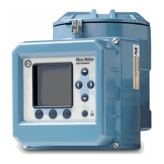
- Page 1 Installation Manual 20001008, Rev BA February 2015 ® Micro Motion Model 3700 Transmitter (MVD) or Model 3350 Peripheral Installation manual for field mount...
- Page 2 Information on return procedures and forms are available on our web support system at www.micromotion.com, or by phoning the Micro Motion Customer Service department. Emerson Flow customer service Email: • Worldwide: flow.support@emerson.com...
-
Page 3: Table Of Contents
Contents Contents Chapter 1 Planning........................5 Installation kit ........................Choose a location........................Cable lengths ......................... Prepare conduit openings for ATEX Zone 1 ................(Optional) Orient the Model 3350 or Model 3700 ..............Chapter 2 Mounting........................11 Mount the applications platform.................... 11 Mount the core processor ...................... - Page 4 Model 3700 Transmitters or Model 3350 Peripherals - Field Mount...
-
Page 5: Chapter 1 Planning
Planning Planning This installation manual explains basic installation guidelines for installing the Micro Motion Model 3350 or Model 3700 MVD applications platform. For information on I.S. applications, refer to Micro Motion approval documentation. For complete instructions about configuration, maintenance, and service, refer to the instruction manual shipped with the transmitter. -
Page 6: Choose A Location
Planning Choose a location Choose a location for the transmitter based on the requirements described below. WARNING! Improper installation in a hazardous area can cause an explosion. Install the transmitter in an area that is compatible with the rating on the approvals tag. See Figure 1-3. - Page 7 Planning Figure 1-3: Top view dimensions inches (mm) 5 1/16-inch (129 mm) clearance for removal of circuit boards Approvals tag 11 5/16 (288) 6 1/8 (158) 8 11/16 (221) 15 1/2 (394) Figure 1-4: Conduit openings view dimensions 2 x 2 13/17 (71) 1 7/8 inches...
-
Page 8: Cable Lengths
Planning Cable lengths Maximum cable length from the sensor to the Model 3700 transmitter depends on the installation type and cable type. Installation type Maximum cable length 4-wire remote transmitter Figure 1-5, and Table 1-1 for maximum length of the 4-wire cable Remote core processor with remote Figure... -
Page 9: Prepare Conduit Openings For Atex Zone 1
Planning Table 1-1: Maximum cable lengths between sensor and transmitter Cable type Wire gauge Maximum length Micro Motion 4-wire Not applicable • 1000 ft (300 m) without Ex-approval • 500 ft (150 m) with IIC-rated sensors • 1000 ft (300 m) with IIB-rated sensors Micro Motion 9-wire Not applicable... - Page 10 Planning Figure 1-7: Orientation examples Conduit openings left Conduit openings for intrinsically safe sensor wiring Display cover Conduit openings for non-intrinsically safe input/output wiring Conduit openings right Conduit openings down Model 3700 Transmitters or Model 3350 Peripherals - Field Mount...
-
Page 11: Chapter 2 Mounting
Mounting Mounting Mount the applications platform • For flat-surface mounting, see Section 2.1.1. • For pole mounting, see Section 2.1.2. 2.1.1 Mount to a flat surface 1. Mount all four bolts to the same surface. 2. If mounting surface is not flat, use washers to shim the bracket. 3. - Page 12 Mounting 2.1.2 Mount to a pole Figure 2-2: Pole mounting example 4 x 5/16 inch nut (user-supplied) 2 x 5/16-inch U bolt for 2-inch pipe (user-supplied) Model 3700 Transmitters or Model 3350 Peripherals - Field Mount...
-
Page 13: Mount The Core Processor
Mounting Mount the core processor Use this section only if you are installing a remote transmitter using a remote core processor or a remote enhanced core processor. See Figure 1-6. If you have a 4-wire remote installation, go to Section 3.1. - Page 14 Mounting Model 3700 Transmitters or Model 3350 Peripherals - Field Mount...
-
Page 15: Chapter 3 Wiring
Wiring Wiring Connect input and output wiring Figure 3-1 shows the location of the wiring terminals on the Model 3350 or Model 3700. 1. Using a flat-head screwdriver, loosen the four captive screws that secure the display cover to the housing. 2. - Page 16 Wiring Table 3-1: Input/output wiring terminals Terminal number Designation 1 – Primary 4–20 mA output / HART 3 – Secondary 4–20 mA output 5 – Frequency input 5 – Discrete input 1 5 – Discrete input 2 11 (B line) 12 (A line) RS-485 output 20 –...
-
Page 17: Connect The Model 3700 To The Sensor
Wiring Connect the Model 3700 to the sensor • If you are installing the Model 3350 controller, this step is not required. Go to Section 3.4. • To connect the Model 3700 transmitter to a Micro Motion sensor, follow the instructions in this section. - Page 18 Wiring Figure 3-3: 4-wire cable to Model 3700 standard and remote core processors Core processor terminals 4-wire cable Model 3700 terminals Blue terminal block Maximum cable length: Figure 3-1 Table 1-1 RS-485A (White) RS-485B (Green) User-supplied or factory-supplied cable VDC– (Black) VDC+ (Red) 16 RS-485B (Green) 15 RS-485A (White)
- Page 19 Wiring To wire the remote core processor to the transmitter: 1. Use one of the following methods to shield the wiring: Installation method Procedure Unshielded wiring in continuous metallic conduit that provides 360° Go to Step 8 termination shielding for the enclosed wiring A user-supplied cable gland with shielded cable or armored cable, Go to Step 8 terminate the shields in the cable gland.
- Page 20 Wiring Figure 3-5: Gland nut and clamping insert 4 1/2 in (114 mm) 3/4 in (19 mm) Gland nut Gland clamping insert 7/8 in (22 mm) 7/8 in Gland body (22 mm) Shielded heat shrink 6. For connection at the core processor housing, prepare shielded cable as follows (for armored cable, omit steps d, e, f, g): a.
- Page 21 Wiring Figure 3-7: Shielded heat shrink covering exposed drain wires g. Position gland clamping insert so the interior end is flush with the heat shrink. h. Fold the cloth shield or braid and drain wires over the clamping insert and approximately 1/8 inch (3 mm) past the O-ring.
-
Page 22: Wire The Sensor To The Remote Core Processor
Wiring Figure 3-10: Connect the four wires to the numbered slots Power supply + RS-485B (Red wire) (Green wire) RS-485A (White wire) Power supply – (Black wire) Core processor housing internal ground screw 10. Connect the core processor housing internal ground screw if earth ground is required. Earth ground is required if the core processor cannot be grounded via sensor piping, and local codes require internal ground connections. - Page 23 Wiring 1. Refer to Micro Motion’s 9-Wire Flowmeter Cable Preparation and Installation Guide for instructions on cable shielding and preparation: • At the sensor end, follow the instructions for your cable type. • At the core processor end, follow the instructions for your cable type with an MVD transmitter.
-
Page 24: Connect The Power Supply Wiring
Wiring Cable type Procedure Jacketed cable Ground the shield drain wires (the black wire) only on the core processor end, by connecting it to the ground screw inside the lower conduit ring. Do not ground to the core processor’s mounting screw. Do not ground the cable at the sensor junction box. - Page 25 F +44 0800 966 181 Micro Motion Japan ©2015 Micro Motion, Inc. All rights reserved. Emerson Process Management The Emerson logo is a trademark and service mark of Emerson 1-2-5, Higashi Shinagawa Electric Co. Micro Motion, ELITE, ProLink, MVD and MVD Direct Shinagawa-ku...
Need help?
Do you have a question about the Micro Motion 3700 and is the answer not in the manual?
Questions and answers