Table of Contents
Advertisement
Quick Links
Quick Installation Guide
00825-0100-4001, Rev BA
November 2002
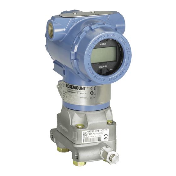
Model 3051 Pressure Transmitter
with HART
®
HART
¢00825-0100-4001I¤
www.rosemount.com
®
Protocol
Step 1: Mount the Transmitter
Step 2: Consider Housing Rotation
Step 3: Set the Jumpers
Step 4: Connect the Wiring and Power Up
Step 5: Configure the Transmitter
Step 6: Trim the Transmitter
Product Certifications
Start
End
Model 3051
Advertisement
Table of Contents

Related Manuals for Emerson 3051


Summary of Contents for Emerson 3051
- Page 1 Quick Installation Guide 00825-0100-4001, Rev BA Model 3051 November 2002 Model 3051 Pressure Transmitter ® with HART Protocol Start Step 1: Mount the Transmitter Step 2: Consider Housing Rotation Step 3: Set the Jumpers Step 4: Connect the Wiring and Power Up...
-
Page 2: Important Notice
Please review the approvals section of the Model 3051 reference manual for any restrictions associated with a safe installation. • Before connecting a HART-based communicator in an explosive atmosphere, make sure the instruments in the loop are installed in accordance with intrinsically safe or non-incendive field wiring practices. - Page 3 Quick Installation Guide 00825-0100-4001, Rev BA Model 3051 November 2002 1: M OUNT THE RANSMITTER Liquid Flow Applications 1. Place taps to the side of the line. 2. Mount level or below the taps. 3. Mount the drain/vent valve upward.
- Page 4 Quick Installation Guide 00825-0100-4001, Rev BA Model 3051 November 2002 Panel Mount Pipe Mount Coplanar Flange Traditional Flange Model 3051T Model 3051H (1) Panel bolts are customer supplied.
-
Page 5: Consider Housing Rotation
Quick Installation Guide 00825-0100-4001, Rev BA Model 3051 November 2002 2: C ONSIDER OUSING OTATION Housing Rotation To improve field access or to better view the optional LCD meter: 1. Loosen the housing rotation set screw. 2. Turn the housing left or right up Housing Rotation Set to 180°... - Page 6 Figure 2 shows wiring connections necessary to power a Model 3051 and enable communications with a hand-held HART communicator. For low-power transmitters, refer to the reference manual.
-
Page 7: Power Supply
Quick Installation Guide 00825-0100-4001, Rev BA Model 3051 November 2002 Power Supply The dc power supply should provide power with less than two percent ripple. The total resistance load is the sum of the resistance of the signal leads and the load resistance of the controller, indicator, and related pieces. -
Page 8: Step 5: Configure The Transmitter
Quick Installation Guide 00825-0100-4001, Rev BA Model 3051 November 2002 5: C ONFIGURE THE RANSMITTER NOTE: A check ( ) indicates the basic configuration parameters. At minimum, these parameters should be verified as part of the configuration and startup procedure. - Page 9 Quick Installation Guide 00825-0100-4001, Rev BA Model 3051 November 2002 Table 1. The Model 275 HART Communicator Fast Key Sequence Function Fast Key Sequence Scaled D/A Trim (4–20 mA Output) 1, 2, 3, 2, 2 Self Test (Transmitter) 1, 2, 1, 1...
-
Page 10: Step 6: Trim The Transmitter
Quick Installation Guide 00825-0100-4001, Rev BA Model 3051 November 2002 6: T RIM THE RANSMITTER NOTE Transmitters are shipped from Rosemount Inc. fully calibrated per request or at the factory default of full scale. Zero Trim A zero trim is a single-point adjustment used for compensating mounting position effects. -
Page 11: Product Certifications
(also with P9 option) Pressure Transmitters — QS Certificate of Assessment - EC No. PED-H-20 Module H Conformity Assessment All other Model 3051/3001 Pressure Transmitters Sound Engineering Practice Transmitter Attachments: Diaphragm Seal - Process Flange - Manifold Sound Engineering Practice... -
Page 12: Hazardous Locations Certifications
Quick Installation Guide 00825-0100-4001, Rev BA Model 3051 November 2002 Hazardous Locations Certifications North American Certifications Factory Mutual (FM) E5 Explosion-Proof for Class I, Division 1, Groups B, C, and D. Dust-Ignition-Proof for Class II, Division 1, Groups E, F, and G. -
Page 13: European Certifications
Quick Installation Guide 00825-0100-4001, Rev BA Model 3051 November 2002 European Certifications I1 CENELEC Intrinsic Safety and Dust Certification No.: BAS 97ATEX1089X II 1 GD EEx ia IIC T5 (Tamb = –60 to +40 °C) EEx ia IIC T4 (Tamb = –60 to +70 °C) Dust Rating: T80 °C (Tamb –20 to 40 °C) IP66... -
Page 14: Japanese Certifications
Quick Installation Guide 00825-0100-4001, Rev BA Model 3051 November 2002 E8 CENELEC Flame-Proof and Dust Certification No.: KEMA 00ATEX2013X II 1/2 GD EEx d IIC T6 (T = –50 to 65 °C) EEx d IIC T5 (T = –50 to 80 °C) Dust rating T90 °C, IP66... - Page 15 Quick Installation Guide 00825-0100-4001, Rev BA Model 3051 November 2002 Australian Certifications I7 SAA Intrinsic Safety Certification No.: AUS EX 1249X Ex ia IIC T4 (T = 70 °C) Ex ia IIC T5 (T = 40 °C) IP65 When connected per Rosemount drawing 03031-1026 The apparatus may only be used with a passive current limited power source Intrinsic Safety application.
- Page 16 Quick Installation Guide 00825-0100-4001, Rev BA Model 3051 November 2002 E7 SAA Explosion-Proof (Flame-Proof) Certification No.: AUS EX 1347X Ex d IIC T6 (T = 40 °C) Ex d IIC T5 (T = 80 °C) DIP T6 (T = 40 °C) DIP T5 (T = 80 °C)
Need help?
Do you have a question about the 3051 and is the answer not in the manual?
Questions and answers