Table of Contents
Advertisement
Quick Links
Advertisement
Table of Contents

Related Manuals for CMA Dishmachines CMA180VL-FL


Summary of Contents for CMA Dishmachines CMA180VL-FL
- Page 1 Owner’s Manual MODEL CMA180VL-FL Installation and Operation Manual Rev 2.00 C M A D I S H M A C H I N E S 1 2 7 0 0 K N O T T A V E N U E...
-
Page 2: Table Of Contents
QUICK SERVICE GUIDE .................. 15 INITIAL PARTS KIT P/N 1100.17 ..............16 AUTO-FILL SOLID STATE TIMER ..............17 WIRE DIAGRAM CMA180VL-FL 240V ............18 WIRE DIAGRAM CMA180VL-FL 240V BOOSTER ONLY ......19 Page MODEL CMA180VL-FL INSTALLATION & OPERATION Rev. 2.00... -
Page 3: Specifications
DEPTH 29” (76.7cm) WIDTH 25 ½” (65cm) HEIGHT 85 ¼”-86 ¼” (216-219)cm STANDARD TABLE HEIGHT 34” (86.3cm) MAX CLEARANCE FOR DISHES 16” (43.2cm) DRAIN CONNECTION (OFF FLOOR) 11 ½“ – 12½“ (29-32cm) Page MODEL CMA180VL-FL INSTALLATION & OPERATION Rev. 2.00... - Page 4 65 PSIG are present, a pressure regulating valve must be installed in the water line to the dishwasher (by others). If flowing pressure is lower than 15 psi, improper machine operation may result. Page MODEL CMA180VL-FL INSTALLATION & OPERATION Rev. 2.00...
-
Page 5: Getting Started
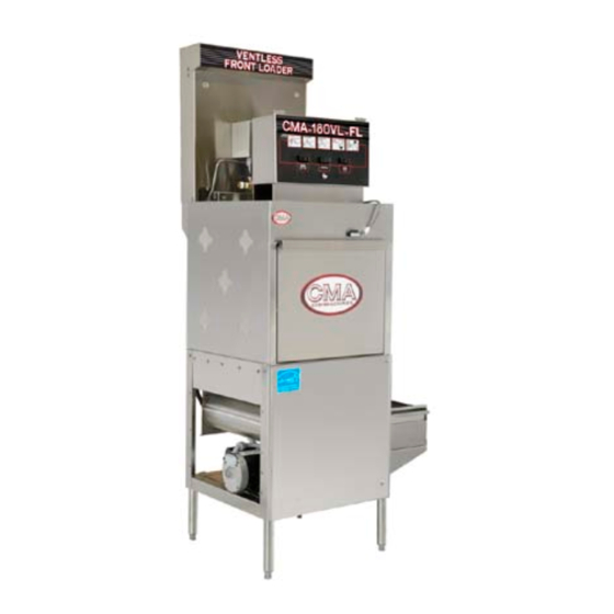
2.1. Introduction to CMA180VL-FL The CMA180VL-FL is a hot water sanitizing, single rack, door-type dishmachine. It is a stand- alone machine featuring a self-contained booster heater. The only external connections necessary are power supply, water supplies, drainpipe, and chemical dispensers. The machine utilizes re-circulated wash water and fresh water final rinse. -
Page 6: Plumbing Chart
The flush-down or cleaning of the condenser is only done at the end of day and sometimes after each service when the main power switch is turned to the off position. Page MODEL CMA180VL-FL INSTALLATION & OPERATION Rev. 2.00... -
Page 7: Receiving And Installation
Account’s drain should be no higher than 11” to allow the machine to drain properly. Electrical and plumbing connections must be made by qualified person who comply with all available Federal, State, and Local Health, Electrical, Plumbing and Safety codes Page MODEL CMA180VL-FL INSTALLATION & OPERATION Rev. 2.00... -
Page 8: Chemical Dispensers
Electrical and plumbing connections must be made by qualified person who comply with all available Federal, State, and Local Health, Electrical, Plumbing and Safety codes Page MODEL CMA180VL-FL INSTALLATION & OPERATION Rev. 2.00... -
Page 9: Water Tempering Kit (Optional)
2.2.4. Water Tempering Kit (Optional) Page MODEL CMA180VL-FL INSTALLATION & OPERATION Rev. 2.00... -
Page 10: Installation Checklist
SEE NOTE FOR BOOSTER HEATER BELOW. c. Press “Auto Fill” switch to activate the water solenoid, adjust the pressure regulator until the gauge reads 20 PSI. NOTE: Booster heater is filled during this procedure. Page MODEL CMA180VL-FL INSTALLATION & OPERATION Rev. 2.00... - Page 11 110-Second steam evacuation cycle at the very end. Once the full cycle is finished, the door safety interlock arm will be retracted thus allowing the doors to wash cabinet to be opened. Page MODEL CMA180VL-FL INSTALLATION & OPERATION Rev. 2.00...
-
Page 12: Electrical Requirements
2.2.7. Electrical Requirements The CMA180VL-FL comes standard factory, wired for 3-phase operation. Check the electrical data plate to confirm this. Refer to “Electrical Requirements” Figure 1-A, for proper wiring instruction for both rectangular booster and wash heaters conversion. Also check the wiring diagram to properly wire the terminal power block, tank heater, and booster heater for 1 phase (or 1B diagram below). -
Page 13: Wiring Options
Install power supply wires, L1, L2 and L3 (3-Phase) to the appropriate terminals marked L1, L2, and L3 on the power block. (If applicable, the high or “wild” leg must be connected to the L2 Terminal.) Page MODEL CMA180VL-FL INSTALLATION & OPERATION Rev. 2.00... -
Page 14: Quick Service Guide
Faulty wash pump contactor Replace contactor, Check exhaust fan. Replace if faulty, Check cam timer setting Cahnge the setting Ventless features not working Faulty # 6 micro switch in cam timer Replace micro switch, properly Page MODEL CMA180VL-FL INSTALLATION & OPERATION Rev. 2.00... -
Page 15: Initial Parts Kit P/N 1100.17
All the parts included in this kit are unique to the CMA180VL-FL dishmachine, and are essential to the “quality” operation and customer service to the CMA180VL-FL unit. -
Page 16: Auto-Fill Solid State Timer
Pre-selected delay period can be adjusted by turning dip switches on for proper time setting. Removal of input power will reset the control. AUTO-FILL SWITCH violet violet WATER SOLENOID VALVE orange blue blue Page MODEL CMA180VL-FL INSTALLATION & OPERATION Rev. 2.00... -
Page 17: Wire Diagram Cma180Vl-Fl 240V
7. Wire Diagram CMA180VL-FL 240V Page MODEL CMA180VL-FL INSTALLATION & OPERATION Rev. 2.01A... -
Page 18: Wire Diagram Cma180Vl-Fl 240V Booster Only
8. Wire Diagram CMA180VL-FL 240V Booster Only Page MODEL CMA180VL-FL INSTALLATION & OPERATION Rev. 2.01A...
Need help?
Do you have a question about the CMA180VL-FL and is the answer not in the manual?
Questions and answers