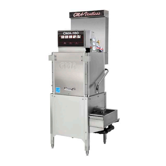
CMA Dishmachines CMA-180VL Service And Parts Manual
Hide thumbs
Also See for CMA-180VL:
- Owner's manual (22 pages) ,
- Parts manual (14 pages) ,
- User manual (2 pages)

Related Manuals for CMA Dishmachines CMA-180VL


Summary of Contents for CMA Dishmachines CMA-180VL
- Page 1 MODEL CMA-180VL Service and Parts Manual Rev 2.01 C M A D I S H M A C H I N E S 1 2 7 0 0 K N O T T A V E N U E GARDEN GROVE, CALIFORNIA 92841...
-
Page 2: Table Of Contents
6.10. Booster Tank Heater (Triangular Flange) ..................28 6.11. Control Box Assembly ........................29 6.12. Heat Recovery System Control Box ....................30 AUTO-FILL SOLID STATE TIMER ..............31 WIRE DIAGRAM CMA-180VL ................. 32 WIRE DIAGRAM CMA-180VL BOOSTER ONLY ........33 Page MODEL CMA-180VL Service & Parts Manual Rev. 2.01... -
Page 3: Specifications
(76.7cm) WIDTH 25 ½” (65cm) HEIGHT 85 ¼”-86 ¼” (216-219)cm STANDARD TABLE HEIGHT 34” (86.3cm) MAX CLEARANCE FOR DISHES 17 ½” (44cm) DRAIN CONNECTION (OFF FLOOR) 11 ½“ – 12½“ (29-32cm) Page MODEL CMA-180VL Service & Parts Manual Rev. 2.01... - Page 4 VOLTS PHASE AMPS ELECTRICAL RATING 332# SHIPPING WEIGHT Page MODEL CMA-180VL Service & Parts Manual Rev. 2.01...
-
Page 5: Getting Started
2. Getting Started 2.1. Introduction to CMA-180VL 2.1.1. Plumbing Chart Page MODEL CMA-180VL Service & Parts Manual Rev. 2.01... - Page 6 (41F -65F) before entering the booster heater. Operation of the CMA-180VL is automatic. When the door is opened and then closed, the wash cycle begins automatically. To initially fill the machine daily, press auto fill rocker switch. The machine is full when water begins to flow into the scrap trap.
-
Page 7: Receiving And Installation
The conduit needs to be of sufficient length and Electrical and plumbing connections must be made by qualified person who comply with all available Federal, State, and Local Health, Electrical, Plumbing and Safety codes Page MODEL CMA-180VL Service & Parts Manual Rev. 2.01... - Page 8 (supplied with your dispenser). 3. A 7/8” detergent injection hole is provided in the back of the wash tank. Remove the S.S. plug and install the detergent fitting (supplied with your dispenser). Page MODEL CMA-180VL Service & Parts Manual Rev. 2.01...
- Page 9 The reference manual supplied with the dispenser shows you how to program it. Keep in mind while reading the reference manual that the CMA-180VL operates in “probe” mode. (This mode is selected by setting a value of “1” in screen 21).
-
Page 10: Straight To Corner Operation Retrofit Instructions
(see red line on the photo) and then mount it on the tray track using the same bolts, washers and lock nuts used for straight application. Page MODEL CMA-180VL Service & Parts Manual Rev. 2.01... -
Page 11: Water Tempering Kit (Optional)
2.2.5. Water Tempering Kit (Optional) Page MODEL CMA-180VL Service & Parts Manual Rev. 2.01... -
Page 12: Installation Checklist
7. A 7/8” chemical probe hole is provided in the wash tank behind wash tank heater cover. 8. A 7/8” detergent fitting hole is provided in the wash tank behind the machine. 9. Check the machine operating temperatures. Adjust if necessary. Page MODEL CMA-180VL Service & Parts Manual Rev. 2.01... - Page 13 When water is observed entering the wash tank this indicates the booster tank is full and removed wire can be connected. Failure to follow these important instructions will destroy the heating element because of dry -firing. Page MODEL CMA-180VL Service & Parts Manual Rev. 2.01...
-
Page 14: Electrical Requirements
Refer to Figure 1-B, for proper wiring instruction for both triangular booster and wash heaters conversion. SINGLE PHASE POWER NOTE: 80amp service is required when CMA-180VL is wired for single-phase with the booster heater. See “Wiring options” section for DUAL 1-phase power supply. -
Page 15: Wiring Options
Install power supply wires, L1, L2 and L3 (3-Phase) to the appropriate terminals marked L1, L2, and L3 on the power block. (If applicable, the high or “wild” leg must be connected to the L2 Terminal.) Page MODEL CMA-180VL Service & Parts Manual Rev. 2.01... -
Page 16: Quick Service Guide
Replace micro switch Machine does not operate when the door is closed Check cam timer motor Replace timer if needed Check ice cube relay Replace if faulty Replace contactor Faulty wash pump contactor Page MODEL CMA-180VL Service & Parts Manual Rev. 2.01... -
Page 17: Initial Parts Kit
Immersion Heater 6 Kw 3hp/1ph, 240V 17523.51 Hi Limit Switch 250 deg NOTE: CMA recommend that this Model CMA-180VL initial parts kit be kept on hand, as a back up supply, in the event your machine should require emergency service. -
Page 18: Exploded Views
Scrap Body SS 17506.60 Door Panel Splash Guard 01579.20 Scrap Trap Drawer 17506.62 180 Splash Shield - lever side 17579.00 Scrap Trap Holder 17546.00 CMA-180VL Skirt 17511.00 Overflow 00449.50 Keyless Lock Page MODEL CMA-180VL Service & Parts Manual Rev. 2.01... -
Page 19: Heat Recovery System
UC 50e Stainless Steel Rinse Nozzle 17598.00 CMA-180 Ventless Support L.H. 03107.51 Flexible Black Hose 3/8” 17597.00 CMA-180 Ventless Support R.H. 03107.00 Flexible Black Hose ½” 40014.00 1/2m x 1/2 Barb Straight 17594.00 CMA-180 Ventless Shroud Page MODEL CMA-180VL Service & Parts Manual Rev. 2.01... -
Page 20: Drain System Assembly
¼-20 Nylon Lock Nut 01320.17 2” PVC Tee SxSxS 17580.00 Drain Lever 05030.10 2” x 3” PVC Tubing 00910.00 ¼”-20 x 1 ½” Hex Head Bolt 01315.17 2” No Hub * #00121.17 includes #00121.18 Page MODEL CMA-180VL Service & Parts Manual Rev. 2.01... -
Page 21: Plumbing System Assembly
03603.20 Water Sol Valve Bonnet ½” 13605.45 Pressure Gauge 180-UC 00786.00 Water Sol Plunger ½” & ¾” w/spring 03202.00 Thermometer Capillary 00707.00 Water Sol Repair Kit JE ½” 17534.50 Gauge Bracket Page MODEL CMA-180VL Service & Parts Manual Rev. 2.01... -
Page 22: Wash Spray System Assembly
1” Comp. Fit.x1”MIP SS 00924.00 SS Washer ¼” 00759.17 Base Quick Release W/Nipple 00341.00 Spray Arm Bearing **P/N 00361.10 Includes Items 11,12 & 6 *P/N 00360.24 Includes Items 11, 12 & 6 Page MODEL CMA-180VL Service & Parts Manual Rev. 2.01... -
Page 23: Final Rinse System Assembly
13607.10 3/8 Compression Fitting Nut (Plated) 13669.45 13642.00 1/2" Male Plug Brass Mixing Chamber SS CMA 180UC 03232.00 1/8 Male Plug 4305.17 Red Silicone Gasket (CMA-180) 13629.00 ½” S.S. Close Nipple Page MODEL CMA-180VL Service & Parts Manual Rev. 2.01... -
Page 24: Door Handle Assembly
Door Handle Spacer (Large) 00606.00 5/16”-18 x 7” Eyebolt 00607.04 Door Handle Grip 00913.00 5/16”-18” Nut 01555.50 Left Door Handle Support 00926.00 5/16” SS Washer 00903.00 ¼”-20 x 1 ¾” Hex Screw Page MODEL CMA-180VL Service & Parts Manual Rev. 2.01... -
Page 25: Pump System Assembly
¼”-20 Nylon Lock Nut 03226.00 Pump “O” Ring 00238.00 3/8” Male Plug 03222.05 Impeller Assy. 00200.30 Pump Assy 04206.00 Pump Cover 00208.20 Slip Joint Nut Friction Ring *P/N 00200.10 Includes Items 1,2,3,4,5 and 6 Page MODEL CMA-180VL Service & Parts Manual Rev. 2.01... -
Page 26: Wash Tank Heater (Triangular Flange)
Heater 6kW 220V Triangular Flange 13417.92 Heater Thermostat 13463.14 Liquid Level Switch 13463.51 Liquid Level Switch Shield 17523.51 Hi-Limit Switch - Wash 250 Degrees 13477.20 7/8” Probe Hole Plug 15518.10 Gasket for Triangular Flange Heater Page MODEL CMA-180VL Service & Parts Manual Rev. 2.01... -
Page 27: Booster Tank Heater (Triangular Flange)
Washer SS 5/16” 13422.71 240V 12KW Triangular Immersion Htr 13417.92 Thermostat 12KW Heater 17523.51 Hi-Limit Switch-Booster 250 degrees 17520.00 Booster Heater Shield* 15518.10 Gasket for Triangular Flange Heater 17560.00 Complete Assembly Page MODEL CMA-180VL Service & Parts Manual Rev. 2.01... -
Page 28: Control Box Assembly
85 Amp Terminal Block-Natural 13426.50 Ground Block 17400.08 30 Amp Terminal Block-Blue 00421.78 Illuminated Plug * Includes timer motor p/n 501.17 and microswitch p/n 411.00 ** Only for the machines with booster heater Page MODEL CMA-180VL Service & Parts Manual Rev. 2.01... -
Page 29: Heat Recovery System Control Box
Ice Cube Relay 220V 12 Amp 00940.50 10-32 X 3/8 Truss Head Screw 0013805 5/16-18 Nylon Insert Lock Nut 00926.00 5/16 SS Washer 00907.00 6-32 X 1/2 SS Panhead Screw 00965.00 6-32 Nylon Insert Lock Nut Page MODEL CMA-180VL Service & Parts Manual Rev. 2.01... -
Page 30: Auto-Fill Solid State Timer
Pre-selected delay period can be adjusted by turning dip switches on for proper time setting. Removal of input power will reset the control. AUTO-FILL SWITCH violet violet WATER SOLENOID VALVE orange blue blue Page MODEL CMA-180VL Service & Parts Manual Rev. 2.01... -
Page 31: Wire Diagram Cma-180Vl
8. Wire Diagram CMA-180VL CONTACTOR CONTACTOR CONTACTOR HEATER PUMP WASH HEATER BOOSTER Page MODEL CMA-180VL Service & Parts Manual Rev. 2.01... -
Page 32: Wire Diagram Cma-180Vl Booster Only
9. Wire Diagram CMA-180VL Booster Only Page MODEL CMA-180VL Service & Parts Manual Rev. 2.01...
Need help?
Do you have a question about the CMA-180VL and is the answer not in the manual?
Questions and answers