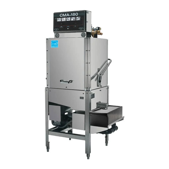
CMA Dishmachines CMA-180 Installation And Operation Manual
Including 480v machines
Hide thumbs
Also See for CMA-180:
- Parts manual (24 pages) ,
- Owner's manual (22 pages) ,
- Quick setup instructions (2 pages)
Table of Contents
Advertisement
Total Restaurant Supply - https://totalsupply1.com - Toll Free 1-800-944-9304 - Local 507-288-9454
2940 Hwy 14 W, Rochester, MN 55901
Owner's Manual
Keep with machine for reference
MODELS CMA-180/180 TALL
Including 480V MACHINES
Installation and Operation
Rev 2.08
C M A D I S H M A C H I N E S
1 2 7 0 0 K N O T T A V E N U E
GARDEN GROVE, CALIFORNIA 92841
8 0 0 - 8 5 4 - 6 4 1 7
F A X 7 1 4 - 8 9 5 - 2 1 4 1
www.cmadishmachines.com
Advertisement
Table of Contents

Subscribe to Our Youtube Channel
Related Manuals for CMA Dishmachines CMA-180


Summary of Contents for CMA Dishmachines CMA-180
- Page 1 Total Restaurant Supply - https://totalsupply1.com - Toll Free 1-800-944-9304 - Local 507-288-9454 2940 Hwy 14 W, Rochester, MN 55901 Owner’s Manual Keep with machine for reference MODELS CMA-180/180 TALL Including 480V MACHINES Installation and Operation Rev 2.08 C M A D I S H M A C H I N E S...
-
Page 2: Table Of Contents
WIRE DIAGRAM FOR CMA-180 WITH BOOSTER HEATER....16 WIRE DIAGRAM FOR CMA-180 BOOSTER ONLY ........17 WIRE DIAGRAM FOR CMA-180 WITHOUT BOOSTER HEATER ..18 WIRE DIAGRAM FOR 480V 180 WITHOUT BOOSTER HEATER ... 19 WIRE DIAGRAM FOR 480V 180 WITH BOOSTER HEATER....20... -
Page 3: Specifications
DIMENSIONS DEPTH 25” (63.5cm) WIDTH 25 ½” (65cm) HEIGHT 59”-60” (150-152cm) STANDARD TABLE HEIGHT 34” (86.3cm) MAX CLEARANCE FOR DISHES 17 ½” (44cm) DRAIN CONNECTION (OFF FLOOR) 11 ½“ – 12½“ (29-32cm) Page MODEL CMA-180 INSTALLATION & OPERATION Rev. 2.08... -
Page 4: Cma-180/Cma-180T
2940 Hwy 14 W, Rochester, MN 55901 1.1. CMA-180/CMA-180T VOLTS PHASE AMPS ELECTRICAL RATING WITHOUT BOOSTER (both High and Low Temp) ELECTRICAL RATING WITH BOOSTER (High Temp) SHIPPING WEIGHT 332# WITHOUT BOOSTER 375# WITH BOOSTER Page MODEL CMA-180 INSTALLATION & OPERATION Rev. 2.08... -
Page 5: Getting Started
Operation of the CMA-180 is automatic. To initially fill the machine daily, press “Auto Fill” rocker switch. Auto Fill timer will fill the machine until water begins to flow into the scrap trap. When the door is opened and then closed, the wash cycle begins automatically. -
Page 6: Receiving And Installation
High Temp machines — for rinse chemical only. Electrical and plumbing connections must be made by qualified person who comply with all available Federal, State, and Local Health, Electrical, Plumbing and Safety codes Page MODEL CMA-180 INSTALLATION & OPERATION Rev. 2.08... -
Page 7: Low Temperature Applications
It is recommended that the 5-1/4% chemical solution be standardized to allow uniform dispensing of the sanitizing solution into the flow of rinse water as the machine operates. At this level, maximum shelf life is available. Page MODEL CMA-180 INSTALLATION & OPERATION Rev. 2.08... -
Page 8: Exhaust Fan Control Kit P/N 17528.00 Instructions
7. Connect power source of 220 Vac or 110 Vac to L1 and L2 (N) on fan control contactor. 8. Connect exhaust fan motor to T1 and T2 on other side of fan control contactor. Page MODEL CMA-180 INSTALLATION & OPERATION Rev. 2.08... -
Page 9: Water Tempering Kit (Optional)
Total Restaurant Supply - https://totalsupply1.com - Toll Free 1-800-944-9304 - Local 507-288-9454 2940 Hwy 14 W, Rochester, MN 55901 2.2.5. Water Tempering Kit (Optional) Page MODEL CMA-180 INSTALLATION & OPERATION Rev. 2.08... -
Page 10: Installation Checklist
9. Check the machine operating temperatures. Adjust if necessary. a. After the machine has warmed up for five to ten minutes (5 – 10 min.), observe the wash and rinse temperatures. The wash temperature must be 155°F Page MODEL CMA-180 INSTALLATION & OPERATION Rev. 2.08... - Page 11 When water is observed entering the wash tank this indicates the booster tank is full and removed wire can be connected. Failure to follow these important instructions will destroy the heating element because of dry -firing. Page MODEL CMA-180 INSTALLATION & OPERATION Rev. 2.08...
-
Page 12: Electrical Requirements
Refer to Figure 1-B, for proper wiring instruction for both triangular booster and wash heaters conversion. SINGLE PHASE POWER NOTE: 80amp service is required when CMA-180 is wired for single-phase with the booster heater. See “Wiring options” section for DUAL 1-phase power supply. -
Page 13: Wiring Options
Install power supply wires, L1, L2 and L3 (3-Phase) to the appropriate terminals marked L1, L2, and L3 on the power block. (If applicable, the high or “wild” leg must be connected to the L2 Terminal.) Page MODEL CMA-180 INSTALLATION & OPERATION Rev. 2.08... -
Page 14: Quick Service Guide
Machine does not operate when the door is closed Check cam timer motor Replace timer if needed, P/N 00409.17 Check ice cube relay Replace if faulty, P/N 00631.05 Replace contactor, P/N 00404.85 Faulty wash pump contactor Page MODEL CMA-180 INSTALLATION & OPERATION Rev. 2.08... -
Page 15: Initial Parts Kit P/N 1100.17
Immersion Heater 6 Kw 3hp/1ph, 240V 17523.51 Hi Limit Switch 250 deg NOTE: CMA recommend that this Model CMA-180 initial parts kit be kept on hand, as a back up supply, in the event your machine should require emergency service. -
Page 16: Auto-Fill Solid State Timer
Pre-selected delay period can be adjusted by turning dip switches on for proper time setting. Removal of input power will reset the control. AUTO-FILL SWITCH violet violet WATER SOLENOID VALVE orange blue blue Page MODEL CMA-180 INSTALLATION & OPERATION Rev. 2.08... -
Page 17: Wire Diagram For Cma-180 With Booster Heater
Total Restaurant Supply - https://totalsupply1.com - Toll Free 1-800-944-9304 - Local 507-288-9454 2940 Hwy 14 W, Rochester, MN 55901 7. Wire Diagram for CMA-180 With Booster Heater Page MODEL CMA-180 INSTALLATION & OPERATION Rev. 2.08... -
Page 18: Wire Diagram For Cma-180 Booster Only
Total Restaurant Supply - https://totalsupply1.com - Toll Free 1-800-944-9304 - Local 507-288-9454 2940 Hwy 14 W, Rochester, MN 55901 8. Wire Diagram for CMA-180 Booster Only GROUND RINSE SIGNAL DETERGENT HI LIMIT SWITCH WASH TANK ADJ. 12kW PUMP THERMOSTAT HEATER... -
Page 19: Wire Diagram For Cma-180 Without Booster Heater
Total Restaurant Supply - https://totalsupply1.com - Toll Free 1-800-944-9304 - Local 507-288-9454 2940 Hwy 14 W, Rochester, MN 55901 9. Wire Diagram for CMA-180 Without Booster Heater Page MODEL CMA-180 INSTALLATION & OPERATION Rev. 2.08... -
Page 20: Wire Diagram For 480V 180 Without Booster Heater
Total Restaurant Supply - https://totalsupply1.com - Toll Free 1-800-944-9304 - Local 507-288-9454 2940 Hwy 14 W, Rochester, MN 55901 10. Wire Diagram for 480V 180 Without Booster Heater Page MODEL CMA-180 INSTALLATION & OPERATION Rev. 2.08... -
Page 21: Wire Diagram For 480V 180 With Booster Heater
Total Restaurant Supply - https://totalsupply1.com - Toll Free 1-800-944-9304 - Local 507-288-9454 2940 Hwy 14 W, Rochester, MN 55901 11. Wire Diagram for 480V 180 With Booster Heater Page MODEL CMA-180 INSTALLATION & OPERATION Rev. 2.08...
Need help?
Do you have a question about the CMA-180 and is the answer not in the manual?
Questions and answers