Table of Contents

Related Manuals for Vigitron Vi3010


Summary of Contents for Vigitron Vi3010
- Page 1 MaxiiNet VI3010 Installation and Getting Started Guide 10 Port Series PoE+ L2 Plus Managed Switch 2014 Vigitron, Inc. All rights reserved. All brand and product names are trademarks or registered trademarks of their respective companies.
- Page 2 MaxiiNet Vi3010 Gigabit Managed Switch Installation and Getting Started Guide...
-
Page 3: About This Guide
Warranty See the Customer Support/Warranty booklet included with the product. A copy of the specific warranty terms applicable to Vigitron’s products and replacement parts can be obtained from Vigitron’s Sales and Service Office or authorized dealer. -
Page 4: Table Of Contents
Contents About This Guide ................................3 Compliances and Safety Statements ..........................5 Introduction ................................... 8 Description of Hardware .............................. 10 Network Planning ................................ 12 Installing the Switch ..............................15 Operation of Web-Base Management ......................... 22 Making Network Connections ............................. 24 Cable Labeling and Connection Records ........................ -
Page 5: Compliances And Safety Statements
Compliances and Safety Statements This equipment has been tested and found to comply with the limits for a Class A FCC-Class A computing device pursuant to Subpart J of part 15 of FCC Rules, which are designed to provide reasonable protection against such interference when operated in a commercial environment. - Page 6 Fig. Add an arrester between outdoor device and this switch Supports SFP manufactured by Vigitron and others conforming to MSA standards. Differences between manufacturers may result in difference in performance or provided information.
- Page 7 WARNING: Self-demolition on this product is strictly prohibited. Damages caused by self-demolition will be charged for repairing fees. Do not place product outdoor or in a sandstorm. Before installation, please make sure input the power supply and product specifications are compatible to each other.
-
Page 8: Introduction
Introduction Overview The Vi3010 PoE switch, next generation network solutions, is an affordable managed switch that provides a reliable infrastructure for your business network. These switches deliver more intelligent features you need to improve the availability of your critical business applications, protect your sensitive information, and optimize your network bandwidth to deliver information and applications more effectively. - Page 9 Switch The switch performs a wire-speed, non-blocking switching fabric. This allows wire- Architecture speed transport of multiple packets at low latency on all ports simultaneously. The switch also features full-duplex capability on all ports, which effectively doubles the bandwidth of each connection. This switch uses store-and-forward technology to ensure maximum data integrity.
-
Page 10: Description Of Hardware
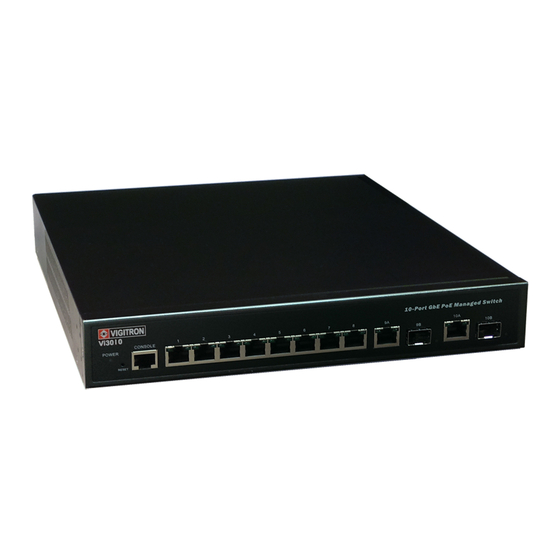
SFP Transceiver Vi3010 supports the Small Form Factor Pluggable (SFP) transceiver slots. The SFP transceiver slots are shared with RJ-45 port 9 to 10. In the default configuration, if Slots a SFP transceiver (purchased separately) is installed in a slot and has a valid link on the port, the associated RJ-45 port is disabled. - Page 11 The Vi3010 has a display panel for system and port indications that simplify Port and System installation and network troubleshooting. The LEDs are located on left hand side of Status LEDs the front panel for easy viewing. Details are shown below and described in the following tables.
-
Page 12: Network Planning
Ethernet network to significantly increase bandwidth while using conventional cabling and network cards. The Vi3010 has auto MDIX and 2 slots for the removable SFP module which support Application comprehensive types of fiber connection, such as LC and BiDi-LC modules. It is not... - Page 13 Vi3026 Vi3026 Figure 4: Network Connection between Remote Site and Central Site Vi3026 Figure 5: Peer-to-peer Network Connection...
- Page 14 Vi3026 Figure 6: Office Network Connection...
-
Page 15: Installing The Switch
Make sure the twisted-pair Ethernet cable is always routed away from power lines, radios, transmitters, or any other electrical interference. Make sure that Vi3010 is connected to a separate grounded power outlet that provides 100 to 240 VAC, 50 to 60 Hz. Ethernet Cabling To ensure proper operation when installing the switch into a network, make sure that the current cables are suitable for 100BASE-TX or 1000BASE-T operation. -
Page 16: Equipment Checklist
After unpacking the switch, please check the contents make sure you have Checklist received all of the components. Also make sure you have all other necessary installation equipment before beginning the installation process. Package Contents Vi3010 GbE Management Switch Four Adhesive Rubber Feet AC Power Cord ... - Page 17 Mounting The switch can be mounted in a standard 19 inch equipment rack, on a desktop, or a shelf. Mounting instructions for each type of site is as follows. Rack Mounting Before rack mounting the switch, please pay attention to the following factors: ...
- Page 18 Step3. If you’re only installing a single switch, turn to “Connection to a Power Source” at the end of this chapter. Step4. If you’re installing multiple switches, mount them in the rack, one below the other in any order. Desktop or Shelf Mounting: Step1.
- Page 19 CAUTION: Use only supported genuine manufacture mini- GBICs with your switch. Non-manufacture mini-GBIC might have compatibility issues, and may result in product malfunction. Figure 12: Inserting an SFP Transceiver into a Slot The SFP slots support the following optional SFP transceivers: Description 1000Base-SX GE SFP Fiber Module, LC Multi-Mode 850nm 1000Base-SX GE SFP Fiber Module, LC Multi-Mode 1310nm 2km...
- Page 20 To Install a SFP Transceiver, Do the Following: Step1. Consider the network and cabling requirements to select an appropriate SFP transceiver type. Step2. Insert the transceiver with the optical connector facing outward and the slot connector facing down. Note that SFP transceivers are keyed so they can only be installed in one orientation.
- Page 21 The RJ-45 serial port on the switch’s front panel is used to connect to the switch for Connecting to the out-of-band console configuration. The command-line-driven configuration Console Port program can be accessed from a terminal or a PC running a terminal emulation program.
-
Page 22: Operation Of Web-Base Management
“admin” and the default password is blank. For first time use, please enter the default username and password, then click the <Login> button. The login process now is completed. The server 192.168.20.15 at Vi3010 requires a username and password. Vi3010 Web User Interface NOTE: If you need to configure the function or parameter, please refer to the details in the User’s Guide. - Page 23 Vi3010 Web Help Function...
-
Page 24: Making Network Connections
Making Network Connections Connecting The switch is designed to be connected to 10, 100, or 1000Mbps network cards in Network Devices PCs and servers, as well as, to other switches and hubs. It may also be connected to remote devices using optional SFP transceivers. Twisted-Pair Each device requires an unshielded twisted-pair (UTP) cable with RJ-45 connectors Devices... - Page 25 Step2. If the device is a network card and the switch is in the wiring closet, attach the other end of the cable segment to a modular wall outlet that is connected to the wiring closet. See the section “Network Wiring Connections.” Otherwise, attach the other end to an available port on the switch.
- Page 26 An optional Gigabit SFP transceiver can be used as a backbone connection between Fiber Optic SFP switches, or as a connection to a high-speed server. Devices Each single-mode fiber port requires 9/125 micron single-mode fiber optic cable with an LC connector at both ends. Each multimode fiber optic port requires 50/125 or 62.5/125 micron multimode fiber optic cabling with an LC connector at both ends.
-
Page 27: Connectivity Rules
When adding hubs to your network, please note that because switches break up Connectivity Rules the path for connected devices into separate collision domains, you should not include the switch or connected cabling in your calculations for cascade length involving other devices. All Category 5 UTP cables that are used for 100BASE-TX connections should also 1000Base-T Cable work for 1000BASE-T, provided that all four wire pairs are connected. - Page 28 100 Mbps Fast Ethernet Collision Domain Cable Type Maximum Cable Length Connector Category 5, 5e or 100.m (328 ft) RJ-45 6 100-ohm UTP or STP Table 9: Maximum Fast Ethernet Cable Lengths...
-
Page 29: Cable Labeling And Connection Records
Cable Labeling and Connection Records When planning a network installation, it is essential to label the opposing ends of cables and record where each cable is connected. This will allow the user to easily locate inter-connected devices, isolate faults, and change the topology without the need for unnecessary time consumption. -
Page 30: Troubleshooting
Because the series Vi3010 behave in this way (in compliance with the IEEE802.3 standard), if a device connected to the switch has a fixed configuration at full duplex, the device will not connect correctly to the switch. - Page 31 Symptom Action POWER LED is Off Check connections between the switch, the power cord, and the wall outlet. Contact your dealer for assistance. Link LED is Off Verify that the switch and attached device are powered on. ...
-
Page 32: Power And Cooling Problems
Power and Cooling Problems If the power indicator does not turn on when the power cord is plugged in, you Installation may have a problem with the power outlet, power cord, or internal power supply. However, if the unit powers off after running for a while, check for loose power connections, power losses, or surges at the power outlet. -
Page 33: Cables
Cables For 10/100BASE-TX connections, the twisted-pair cable must have two pairs of Twisted-Pair Cable wires. For 1000BASE-T connections the twisted-pair cable must have four pairs of and Pin wires. Each wire pair is identified by two different colors. For example, one wire Assignment might be green and the other, green with white stripes. - Page 34 MDI Signal Name MDI-X Signal Name Transmit Data plus (TD+) Receive Data plus (RD+) Transmit Data minus (TD-) Receive Data minus (RD-) Receive Data plus (RD+) Transmit Data plus (TD+) Receive Data minus (RD-) Transmit Data minus (TD-) 4, 5, 7, 8 Not used Not used Table 11: 10/100BASE-TX MDI and MDI-X Port Pin outs...
- Page 35 EIA/TIA 568B RJ-45 Wiring Standard 10/100BASE-TX Crossover Cable Figure 21: Crossover Wiring All 1000BASE-T ports support automatic MDI/MDI-X operation, so you can use 1000Base-T Pin straight-through cables for all network connections to PCs or servers, or to other Assignments switches or hubs. The table below shows the 1000BASE-T MDI and MDI-X port pin outs.
- Page 36 NOTE: That when testing your cable installation, be sure to include all patch cables between switches and end devices. If your existing Category 5 installation does not meet one of the test parameters for Adjusting Existing 1000Base-T, there are three measures that can be applied to try and correct the Category 5 Cabling problem: to Run 1000Base-T...
-
Page 37: Specifications
Specifications Physical Ports 2 100/1000Mbps SFP Fiber ports 2 GbE Combo Port TP/ (100/1000M) SFP Characteristics Network Interface Ports 1-8: RJ-45 Connector 10BASE-T: RJ-45 (100-ohm, UTP cable; Category 3 or better) 100BASE-TX: RJ-45 (100-ohm, UTP cable; Category 5 or better) 1000BASE-T: RJ-45 (100-ohm, UTP or STP cable;... -
Page 38: Switch Features
Switch Features Store-and-forward Forwarding Mode Throughput 35.712Mpps Flow Control Full-Duplex: IEEE 802.3x Half-Duplex: Back pressure In-Band Management SSH/SSL, Telnet, SNMP, or HTTP Management Features Out-Of-Band RS-232 (RJ-45) console port Management HTTP, TFTP in-band, Console out-of-band Software Loading IEEE 802.3 => 10Base-T Ethernet (Twisted-pair Copper) Standards IEEE 802.3u =>... -
Page 39: Compliances
Compliances 10Base-T IEEE 802.3 specification for 10 Mbps Ethernet over two pairs of Category 3, 4, or 5 UTP cable. 100Base-T IEEE 802.3u specification for 100 Mbps Ethernet over two pairs of Category 5 UTP cable. 1000Base-LH Specification for long-haul Gigabit Ethernet over two strands of 9/125 micron core fiber cable. - Page 40 A 100 Mbps network communication system based on Ethernet and Fast Ethernet the CSMA/ CD access method. Full Duplex Transmission method that allows two network devices to transmit and receive concurrently, effectively doubling the bandwidth of that link. Gigabit A 1000 Mbps network communication system based on Ethernet Ethernet and the CSMA/ CD access method.
- Page 41 Telecommunications Industry Association. Transmission Control Protocol suite that includes TCP as the primary transport Protocol/Internet protocol and IP as the network layer protocol. Protocol (TCP/IP) UDP provides a datagram mode for the packet-switched User Datagram Protocol (UDP) communications. It uses the IP as the underlying transport mechanism to provide access to IP-like services.
-
Page 42: Warranty
This warranty does not apply if, in the judgment of Vigitron, Inc., the Product fails due to damage from shipment, handling, storage, accident, abuse or misuse, or if it has been used or maintained not conforming to Product manual instructions, has been modified, or serial number removed or defaced. -
Page 43: Contact Information
Contact Information Vigitron, Inc. 7810 Trade Street, Suite 100 San Diego, CA 92121 support@vigitron.com Tel: (858) 484-5209 Fax: (858) 484-1205 www.vigitron.com...
Need help?
Do you have a question about the Vi3010 and is the answer not in the manual?
Questions and answers