
Related Manuals for Vigitron MaxiiNet Vi32226


Summary of Contents for Vigitron MaxiiNet Vi32226
- Page 1 MaxiiNet Vi32226 Operational Manual Vi32226 Release F32226V1.065 © 2020 Vigitron, Inc. All rights reserved. All brand and product names are trademarks or registered trademarks of their respective companies.
-
Page 2: Section 1: About This Manual
Section 1: About This Manual 1.0 Copyright Copyright © 2020 Vigitron, Inc. All rights reserved. The products and programs described in this User’s Manual are licensed products of Vigitron Inc. This User’s Manual contains proprietary information protected by copyright, and this User’s Manual and all accompanying hardware, software, and documentation are copyrighted. -
Page 3: Disclaimer
1.5 Disclaimer Vigitron, Inc. does not warrant that the hardware will work properly in all environments and applications, and makes no warranty and representation, either implied or expressed, with respect to the quality, performance, merchantability, or fitness for a particular purpose. Vigitron disclaims liability for any inaccuracies or omissions that may have occurred. -
Page 4: Section 2: Compliances And Safety Statements
Section 2: Compliances and Safety Statements 2.0 FCC Class A This equipment has been tested and found to comply with the limits for a Class A computing device pursuant to Subpart J of part 15 of FCC Rules, which are designed to provide reasonable protection against such interference when operated in a commercial environment. -
Page 5: Ce Declaration Of Conformance For Emi And Safety (Eec)
2.3 CE Declaration of Conformance for EMI and Safety (EEC) This equipment has been tested and found to comply with the protection requirements of European Emission Standard EN55022/EN61000-3 and the Generic European Immunity Standard EN55024. 2.4 UL Mark Ul 60950-1 Information Technology Equipment - Safety - Part 1: General Requirements - Edition 2 - Revision Date 2014/05/13 2.5 EMC... - Page 6 The Vi32226 supports SFP conforming to MSA standards, although differences between manufacturers can affect performance. For best results, use Vigitron SFPS. NOTE: The switch is an indoor device. If it will be used in an outdoor environment or connects with some outdoor device, then it must use a lightning arrester to protect the switch.
-
Page 7: Related Publications
2.6 Related Publications The following publication gives specific information on how to operate and use the management functions of the switch. 2.7 Revision History The User’s Manual This section summarizes the changes in each revision of this guide. Release Date Revision F32226V1.065 Updating several functions may require rebooting the switch. -
Page 8: Table Of Contents
Contents Section 1: About This Manual ..........................2 1.0 Copyright ..........................2 1.1 Purpose ..........................2 1.2 Audience ..........................2 1.3 Conventions .......................... 2 1.4 Warranty ..........................2 1.5 Disclaimer ..........................3 Section 2: Compliances and Safety Statements ..................... 4 2.0 FCC Class A .......................... - Page 9 5.4 Mounting ..........................22 5.5 Rack Mounting........................22 5.6 To Rack-Mount Devices ..................... 23 5.7 Installing an Optional SFP Transceiver ................23 5.8 Installing an SFP Transceiver ..................... 24 5.9 Connecting to a Power Source .................... 24 Section 6: Making Network Connections ......................25 6.0 Connecting to a Network Devices ..................
- Page 10 Section 12: VLAN Settings ............................ 56 12.0 VLAN Mode ........................56 12.1 VLAN Member (Port Based) .................... 57 12.2 VLAN Member Settings (Tag Based) ................59 12.3 Multi to 1 Setting ......................60 12.4 Non-Association Port Setting ................... 62 Section 13: Per Port Counter ..........................63 13.0 Transmit Packet and Receive Packets ................
- Page 11 19.3 IGMP Snoop V1 & V2 ...................... 86 19.4 VLAN Uplink ........................87 19.5 UDP/TCP Alert Messages ....................88 19.6 SNMP Settings ........................89 19.7 SNMP Trap States ......................92 Section 20: Log Out .............................. 93 20.0 Log Out Procedure ......................93 Section 21: Glossary .............................
- Page 12 Ethernet Type ........................98 F ..............................98 FTP ............................98 Fast Leave ..........................98 H ..............................98 Host Defined Power Limit ....................98 HTTP............................. 99 HTTPS ..........................99 I ..............................99 ICMP ............................. 99 IEEE 802.1X ......................... 99 IGMP........................... 100 IGMP Querier ........................
- Page 13 P .............................. 103 PCP ............................. 103 PD ............................103 PHY............................. 103 PING ........................... 103 PoE ............................103 Policer ..........................104 Private VLAN ........................104 PTP ............................104 Q .............................. 104 QCE............................. 104 QCL............................. 104 QL ............................104 QoS ............................. 105 R ..............................
- Page 14 TCP ............................. 107 TELNET ..........................107 TFTP ........................... 107 U .............................. 108 UDP............................. 108 User Priority ........................108 V .............................. 108 VLAN ..........................108 VLAN ID ..........................109 Voice VLAN ........................109 SFP Interface Guide ............................110 Connecting Vi32226 ............................113 Contact Information............................
-
Page 15: Section 3: Introduction
The Vi32226 series, the next generation web managed switches from Vigitron, is a portfolio of affordable managed switches that provides a reliable infrastructure for your business network. These switches deliver... -
Page 16: Cabling Guidelines
3.1 Cabling Guidelines Ports 1-24 are 10/100Mbps and will automatically sense network speeds if set to the auto mode or can be forced set to a either network speed. Ports 25 and 26 are 10/100/1000Mbps and can also be set to auto sense speeds or forced speeds. -
Page 17: Network Wiring Connection
that is connected to the wiring closet (see the section “Network Wiring Connections”). Otherwise, attach the other end to an available port on the switch. Make sure each twisted pair cable does not exceed 100 meters (328 ft.) in length. NOTE: Avoid using flow control on a port connected to a hub unless it is actually required to solve a problem. -
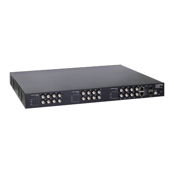
Page 18: Vi32226 - Front View
3.4 Vi32226 – Front View 3.5 Vi32226 – Rear View Page | 18... -
Page 19: Section 4: Description Of Hardware
Section 4: Description of Hardware 4.0 1000Base-T Ports The switch contains 24100BASE-T RJ45 and 2, 1000Mbps ports. All RJ45 ports support automatic MDI/MDI-X operation, auto-negotiation and IEEE 802.3x auto-negotiation of flow control, so the optimum data rate and transmission can be selected automatically. 4.1 SFP Transceivers Slots Vi32226 supports the Small Form Factor Pluggable (SFP) transceiver... -
Page 20: Ports And System Status Leds
4.2 Ports and System Status LEDs The Vi32226 includes a display panel for system and port indications that simplify installation and network troubleshooting. The LEDs are located on left hand side of the front panel for easy viewing. Details are shown below and described in the following tables. -
Page 21: Section 5: Installing The Switch
Section 5: Installing the Switch 5.0 Selecting a Site The switch can be mounted in a standard 19-inch equipment rack or on a flat surface. Be sure to follow the guidelines below when choosing a location. • The site should: o Be at the center of all the devices you want to link and near a power outlet. -
Page 22: Equipment Checklist
Figure 7: RJ45 Connections Figure 8: SFP Transceiver 5.2 Equipment Checklist After unpacking this switch, please make sure you have received all the components. And before beginning the installation process, be sure you have all other necessary installation equipment. 5.3 Package Contents Contents include: Vi32226 16-port extended Coax, 8-port standard PoE network... -
Page 23: To Rack-Mount Devices
Mechanical Loading: Do not place any equipment on top of a • rack-mounted unit. Circuit Overloading: Be sure that the supply circuit to the rack • assembly is not overloaded. Grounding: Rack-mounted equipment should be properly • grounded. 5.6 To Rack-Mount Devices Step 1. -
Page 24: Installing An Sfp Transceiver
5.8 Installing an SFP Transceiver Step 1. Consider network and cabling requirements to select an appropriate SFP transceiver type. Step 2. Insert the transceiver with the optical connector facing outward and the slot connector facing down. Note that the SFP transceivers are keyed so they can only be installed in one orientation. -
Page 25: Section 6: Making Network Connections
Section 6: Making Network Connections 6.0 Connecting to a Network Devices The switch is designed to be connected to 10, 100 or 1000Mbps network cards in PCs and servers, as well as, to other switches and hubs. It may also be connected to remote devices using optional SFP transceivers. 6.1 Twisted-Pair Devices Each device requires an unshielded twisted-pair (UTP) cable with RJ45... -
Page 26: Network Wiring Connections
Step 2. If the device is a network card and the switch is in the wiring closet, attach the other end of the cable segment to a modular wall outlet that is connected to the wiring closet (see the section “Network Wiring Connections”). -
Page 27: Section 7: Troubleshooting
Section 7: Troubleshooting 7.0 Basic Troubleshooting Tips Most problems are caused by the following situations. Check for these items first when starting your troubleshooting: Connecting to devices that have a fixed full- duplex • configuration. The RJ45 ports are configured as “Auto”. That is, when connecting to attach devices, the switch will operate in one of two ways to determine the link speed and the communication mode (half duplex or full duplex):... - Page 28 Check the Port Configuration. A port on your switch may not be • operating as you expect because it has been put into a “blocking” state by Spanning Tree, GVRP (automatic VLANs), or LACP (automatic trunking). (Note that the normal operation of the Spanning Tree, GVRP, and LACP features may put the port in a blocking state.) Or, the port just may have been configured as disabled through software.
-
Page 29: Section 8: Operation Of Web-Based Management
Section 8: Operation of Web-Based Management 8.0 Initial Configuration This chapter instructs you on how to configure and manage the Vi32226 through the web user interface. With this facility, you can easily access and monitor through any one port of the switch and all the status of the switch, including MIBs status, each port activity, Spanning tree status, port aggregation status, multicast traffic, VLAN and priority status, even illegal access record and so on. - Page 30 NOTE: When you log into the Switch, you must first type the user name and password and then press enter. When you log into the Vi32226 switch Web UI management, you can use ipv4 only. To optimize the display effect, we recommend you use either IE, Firefox, or Chrome OS and have the resolution 1024x768.
-
Page 31: Section 9: Administration
Section 9: Administration 9.0 Prior to Logging On Note the default address for the switch is 192.168.1.133. To access the switch for programming, your computer must be on the same subnet using any final value between 2 and 254, excluding 133. 9.1 Logging On Enter the correct administrator name and password after the login •... - Page 32 After logging in the following page will appear Full Version Lite Version Page | 32...
-
Page 33: System Ip Configuration
Selecting Operating Mode: The Vi32226 provides two separate configuration modes. The lite version provides set-ups for addressing, PoE and bandwidth, while the full mode provides for all set-ups. These modes can be used to simplify set-ups and operations. NOTE: In the switch icon, if either the fiber port or the copper port is connected, both ports will show as active. -
Page 34: System Status
Subnet Mask: Enter a valid range. For example: 255.255.255.0 will be used for class C IP Addresses. Gateway: Enter the network gateway IP address. IP Configure: Select Static or DHCP. Select will operate based on the above entries. If DHCP, the switch must be connected to server that will provide an address. -
Page 35: Load Default
Auto Logout: If the Idle Time Security is selected + the Auto Logout when the non-activity time period is reached, the system will log the user out and return to the log in screen. NOTE: If only the Idle Time Security function is selected, Auto logout will be the default mode for this function. -
Page 36: Firmware Update
9.5 Firmware Update When pressing the update button, it redirects. If the system does not redirect or “webpage not found”, please enter the address http://192.168.1.133. After the “Update” button is pressed, the existing code will be erased. After this is complete, select the new file and press “Update”. Page | 36... - Page 37 Page | 37...
- Page 38 Reboot Device: If operation becomes unstable, select “Reboot Device” and press confirm. Using this function will not reset the hardware. Page | 38...
-
Page 39: Section 10: Poe
Section 10: PoE 10.0 PoE Status Power Mode: Host defined Power Limit: Power is determined by port setting, which can be any variable within the range of the selected class power. Class defined Power Limit: Power is defined by the upper limit of the selected class. -
Page 40: Poe Setting
10.1 PoE Setting 1. Select Port. 2. Select Enable/Disable. 3. Select class as Either AF or AT. 4. Input the PoE power level. 5. Select Update: Actual status will be displayed in chart below. Page | 40... - Page 41 1. In the Port Setting page, click on the “Port Priority” box to display a dropdown list of the current settings. The default is port 1 as the highest priority through port 24 as the lowest. 2. To change the priority of a port, left click on one of the ports in the “Port”...
-
Page 42: Poe Event Counter
10.2 PoE Event Counter PoE Event Counter Definitions E0: Port Overload (ICUT) Event E1: Port Short Circuit Limit (ILIM) Event E2: Port MPS Error (DC Disconnect) Event E3: Port Severe Short Circuit Event E4: Port Thermal Shutdown Event E5: Port Temperature Limit Event E6: Main Power Overload Event E7: PoE Auto Check Timeout Event Page | 42... -
Page 43: Poe Power Delay
10.3 PoE Power Delay This setting can be used to delay the application of PoE in cases where a connected device will draw large amounts of power. 1. Enable the Delay mode. If the Delay mode is already enabled, you can disable it by selecting disable. - Page 44 1. Enter the Interval Time- from 1-240min (1mm- 4 hours). This will define the duration the connected device is ping. 2. Enter the Wake up Time- 1-59 seconds. This will define the time it will take for the connected device will respond and become operational. 3.
-
Page 45: Section 11: Port Management
Section 11: Port Management 11.0 Port Configuration Select the Port Number: Select the port number 1-26. NOTE: For ports 25 and 26, port speed is selectable for 100Mbps or 1000Mbps for UTP (copper) connections only. When Fiber STPs are used the port speed will be fixed at 1000Mbps. It cannot be changed and only 1000Mbps SFPs can be used for connected devices. - Page 46 1. In the Port Configuration section, click the down arrow under SecurPort. Select either Enable or Disable to turn the feature on or off. 2. Select the desired ports by checking the boxes next to the ports to be set. 3.
- Page 47 1. In the Port Configuration section, click the down arrow under SecurPort Recovery. Select either Enable or Disable to turn the feature on or off. 2. Select the desired ports by checking the boxes next to the ports to be set.
- Page 48 NOTE: During the bootup sequence, the SecurPort Recovery will disable the SecurPort configuration for up to 3 minutes to allow any connected devices to undergo their initialization process without triggering the SecurPort functionality through their Linking sequence. Auto-Negotiation: Enable: Speed will be Auto Negotiate based on the input. •...
- Page 49 Speed: Select 10Mbps or 100Mbps for ports 1-24. • Select 10Mbps/100Mbps or 1000Mbps (1Gbps) for ports 25/26 • • Note: For ports 25 and 26, copper ports can be set for 10/100/1000Mbps. When using fiber connections, port speed is fixed at 1000Mbps (1G). If attempts are made to program ports 1-24 for 1G, the following popup will appear: Page | 49...
- Page 50 Duplex : Select Full or Half Duplex - for most applications select Full. Pause Enable: Responses to pause commands to prevent traffic • congestion. Disable: disregards pause commands. • NOTE: The recommended setting is Disable as Enable will slow up traffic and may result in loss or delay of packet transmission.
-
Page 51: Port Mirroring
Backpressure Enable: Prevents backpressure in half duplex mode • Disable: Disables function • NOTE: In most applications the switch will operate in the full duplex mode so this function should be set to Disable. Address Learning Enable: Port will learn connected devices MAC – suggested for •... -
Page 52: Bandwidth Control
The select of ports to be mirrored is done by port priority by number. For example, if ports 1 and 2 are selected as source ports, and this is followed by ports 23 and 24, Port 1 will be mirrored at port 23 and port 2 will mirrored at port 24. - Page 53 NOTE: This is an override setting for the port speed (10/100Mbps for ports 1-24 and 10/100/1000Mbps for ports 25/26). If port speed set in the Bandwidth control is lower than the previous selected speed, the value will revert to that speed. The Limitation Of The Bandwidth Control The actual bandwidth should be less than link speed of the port.
- Page 54 This allows the setting of the bandwidth for each port. The Tx rate and Rx rate can be filled with the number ranging from 1 to 255. This number should be multiplied by the selected bandwidth resolution to get the actual bandwidth.
-
Page 55: Broadcast Storm Control
11.3 Broadcast Storm Control The broadcast storm control is used to block the excessive broadcast packets received during the specified time unit. The valid number ranges from 1 to 63. The broadcast packet is only checked at the selected port and the number of broadcast packets is counted in every time unit. -
Page 56: Section 12: Vlan Settings
Section 12: VLAN Settings 12.0 VLAN Mode The Vi32226 switch supports two VLAN modes, tag based and port based. Only one VLAN mode can be enabled at one time. When the tag based VLAN is selected, the administrator can define the handling method of a VLAN tag to the specified port, including “Add Tag”, “don’t care”... -
Page 57: Vlan Member (Port Based)
NOTE: In tag based VLAN mode, adding tag on the port which is used to configure this switch is not allowed, because some NICs cannot recognize 802.1Q tag. Example: Port 1: The 802.1Q tag of every packet outgoing from this port will be removed. - Page 58 Name: Enter a name for your VLAN – maximum of 8 characters. Destination Ports: Select all the port what will be part of the VLAN. Update: Select Update to confirm your port selections. Load Default: If you need to return to the Default setting, select Default. In the above example: Port 1 has been selected as the Read Port.
-
Page 59: Vlan Member Settings (Tag Based)
12.2 VLAN Member Settings (Tag Based) NOTE: This web page allows the administrator configure to Tag-base VLAN member of VID table of 32-entry and Port VID(PVID) source index of each Port. When a tagged packet is received, the Switch compares the tag in the packet with the one defined in the VID table. -
Page 60: Multi To 1 Setting
Delete a VLAN: Select a VLAN from the Select button and press Delete to remove it. To add a group: Select more than one port. Modify a VLAN: Select a VID that you want to modify from the Select drop down. - Page 61 CAUTION: This setting will over ride other VLAN settings. Select the Destination port: Select port to be excluded: • Select the ports excludes them form the VLAN and can be used • for other VLANs. Select “Update”. • NOTE: All ports which are not excluded will be part of the VLAN.
-
Page 62: Non-Association Port Setting
12.4 Non- Association Port Setting Selecting the non-association Port will not send packets to other non- associated port. Page | 62... -
Page 63: Section 13: Per Port Counter
Section 13: Per Port Counter There are three modes. Selecting the mode will display the Transmit and Receive Packets. 13.0 Transmit Packet and Receive Packets Page | 63... -
Page 64: Drop And Receive Packet
13.1 Drop and Receive Packet 13.2 CRC error packet and Receive Packet Page | 64... -
Page 65: Counter Modes Defined
13.3 Counter Modes Defined The 3 different operational modes are: Field Description This category shows both the received Transmit Packet & Receive packet count (excluding the incorrect Packet packet) and the transmitted packet count. This category shows the number of Drop Packet &... -
Page 66: Section 14: Qos Settings
Section 14: QoS Settings 14.0 Priority Mode This setting allows the administrator to set the scheduling mode for the TX packets at each port. 14.1 Setting the Priority Mode This setting sets the scheduling mode for Transmission packets for each port. - Page 67 The numbers indicate the how packets are treated in sequence at each port so if the ratio is 3 Low/ 5 High, the sequence will be 5 packets will be stored in high followed by 3 packets stored in low, etc. Example: If High, Low queue are set to 5, 3, then the traffic at the specific port will go out in the following sequence.
-
Page 68: Class Of Service Configuration
14.2 Class of Service Configuration There are 4 types of CoS for this setting; ie, TCP/UDP port number, IP TOS/DS, 802.1p priority tag and physical port. The administrator can select more than one item for each port. Please note that if more than one type of CoS is selected, the switch will arrange the packet to the assigned queue according the following priority: 1. - Page 69 The administrator can select the protocol that will be forwarded as the specified mode. There are 3 administrator-defined UDP/TCP port groups and many well-known TCP/UDP ports. The administrator- defined port number may be a range or a specific number, depending on the mask.
- Page 70 If 802.1p priority tag is use the following 802.1 field will be used to set the priority queue: Priority Fields 4,5,6, and 7 are High Priority. • • Priority Fields 0,1,2, and 3 are Low Priority. For IP TOS/DS priority, there are 7 kinds of TOS field can be •...
-
Page 71: Section 15: Security
Section 15: Security 15.0 MAC Address Binding MAC Address Binding: This feature establishes a specific relationship between the switch’s physical port and connected device’s MAC address. Only the packets from the assigned MAC address can be transmitted to Page | 71... -
Page 72: Scanning Mac Addresses
the connected port. Up to three MAC addresses can be assigned to each port. • Select the Port. Enter up to three MAC addresses. • Enable Read. • • Enable Binding. Select UpDate. • NOTE: If the MAC address binding function is enabled, the address learning function if selected will be disabled. -
Page 73: Securing Ports Using Mac Addresses
15.2 Securing Ports Using Mac Addresses If no MAC address is entered when the scan is performed, the MAC address of the connected device will be displayed and the “Entry Status” will show “Dynamic” indicating the address can change, depending on the MAC address of the device. - Page 74 The figure shown below illustrates how this function is applied to the real environment. Example: (a) Enable TCP/UDP Filter function. (b) Select “positive” rule. (c) Set port 5 as secure WAN port and select FTP and TELNET as the filtering protocol. (d) Place the server of the selected protocol at the secure WAN port.
-
Page 75: Secure Wan Port: Select The Port To Be Secured
TCP/UDP filter: This feature is used to block specific applications when the switch is connected to a WAN. It is also recommended a similar setting be made at the server side. Function Enable: Enable/Disable function. Port Filtering Rule: • Negative: Select packet(s) will be dropped- others are forwarded. Positive: Selected packet(s) are forwarded- others dropped. - Page 76 Select the port that will allow access to the web pages for programming or viewing switch status. Select “Enable/Disable function”. Page | 76...
-
Page 77: Section 16: Spanning Tree
Section 16: Spanning Tree 16.0 STP Bridge Settings The parameters concerning the configuration of RSTP/STP bridge are described below. Field Description STP Mode Disable: Disable RSTP/STP. STP: Enable STP function. RSTP: Enable RSTP function, including STP. Bridge Priority This field in conjunction with the MAC address forms the Bridge ID. -
Page 78: Stp Port Settings
16.1 STP Port Settings This web page provides an interface for the administrator to set the STP/RSTP port configuration. Field Description Port No. To configure the parameters of RSTP/STP port, the administrator should select a physical port number, assign a priory number, enter the RPC and then press “Submit”... -
Page 79: Loopback Detection Settings
16.2 Loopback Detection Settings This web page provides loopback detection function. When loopback detection function is enabled and a port received its own BPDU, the detection agent drops the loopback BPDU and places the interface in discarding mode. This loopback status can be released automatically, if auto wake up function is enabled. - Page 80 Field Description Loopback Detect Enable/Disable the loopback detect function. Function Auto Wake Up Enable/Disable auto wake up for loopback detection of each ports. Wake-Up Time Set auto wake up time value. Interval Page | 80...
-
Page 81: Section 17: Dhcp Relay Agent
Section 17: DHCP Relay Agent 17.1 Relay Agent Configurations This web page allows the administrator to enable/disable DHCP Relay Agent function. In addition, option 82 message is selectable by setting. Field Description DHCP Relay State Allow the administrator to enable/disable Relay Agent function. - Page 82 Select Update NOTE: On Relay Option 82: This has two components the Circuit ID and the Remote ID. In the case of the Circuit ID a network switch the identifier will be the switch port. In the case of the Remote ID the information relates to the host and is usually the MAC address of the destination.
- Page 83 Page | 83...
-
Page 84: Section 18: Backup And Recovery
Section 18: Backup and Recovery 18.0 Configuration Backup/Recovery 18.1 Back Up This function will download the contents of the EEPROM to the client computer file 18.2 Recovery To upload new firmware, first select the file on your client computer. Enter the switch password and select “Update”. -
Page 85: Section 19: Miscellaneous Settings
Section 19: Miscellaneous Settings 19.0 Miscellaneous Settings Defined Miscellaneous setting is used to configure Output Queue Aging Time, VLAN Striding, IGMP Snooping and VLAN Uplink. 19.1 Output Queue Aging Time This function is used to avoid the poor utilization of the switch. When a packet is stored in a switch for a long time, the time slot defined by the protocol will expire and this packet becomes useless. -
Page 86: Vlan Striding
19.2 VLAN Striding By selecting this function, the switch will forward uni-cast packets to the destination port, no matter whether destination port is in the same VLAN. 19.3 IGMP Snoop V1 & V2 When this function is enabled, the switch will execute IGMP snooping version 1 and version 2 without the intervention of CPU. -
Page 87: Vlan Uplink
19.4 VLAN Uplink In the VLAN, the user can define the “Uplink port”. This is normally the port that attached to the uplink router. This feature is similar to the “Router port”. After that is set. Any frame transferred to the other VLAN member is forwarded only out the uplink port. -
Page 88: Udp/Tcp Alert Messages
19.5 UDP/TCP Alert Messages Sending Out UDP/TCP Alert Messages: This function can be used to integrate alert messages generated by the Switch to various “Health Monitoring” software packages. For a complete list of messages that can be sent out by the Switch see the “SNMP Trap States”... -
Page 89: Snmp Settings
TCP Alerts: To enable or disable this function, click the down arrow located under “TCP Alerts” and select the appropriate option. Type the IP Address of the server into the “TCP Server IP Address” text boxes. The same Subnet mask that is used when setting up the IP address of the Switch will also be used in the TCP messaging. - Page 90 Page | 90...
- Page 91 Field Description The administrator can enter a device name System Description for the identification in the network. The contact person responsible for System Contact maintaining network. System Location The location of this device. Enable/Disable trapped event. The trapped event are: Trap State Power up event.
-
Page 92: Snmp Trap States
19.7 SNMP Trap States This screenshot shows how the switch was configured and on the right side of the screen, how the trap messages are display. The switch IP address is 192.168.1.133. The switch uses SNMPv1. The time and date displayed are from the host computer. SNMP will deliver the following messages: “PoE_On Port xx”... -
Page 93: Section 20: Log Out
Section 20: Log Out 20.0 Log Out Procedure Select: Accept to logout. Back: Returns to the previous page. Hardware Based Loading Default settings: The purpose of this function is to provide a method for the network administrator to restore all configurations to the default value. -
Page 94: Section 21: Glossary
Section 21: Glossary ACE is an acronym for Access Control Entry. It describes the access permission associated with a particular ACE ID. There are three ACE frame types (Ethernet Type, ARP, and IPv4) and two ACE actions (permit and deny). The ACE also contains many detailed and different parameter options that are available for individual application. -
Page 95: Aes
ACL|Rate Limiters: Under this page you can configure the rate limiters. There can be 15 different rate limiters, each ranging from 1-1024K packets per seconds. Under "Ports" and "Access Control List" web-pages you can assign a Rate Limiter ID to the ACE(s) or ingress port(s). AES is an acronym for Advanced Encryption Standard. -
Page 96: Ccm
Continuity Check Message (CCM) is an OAM frame transmitted from a MEP to its peer MEP and used to implement CC functionality. CDP is an acronym for Cisco Discovery Protocol. Drop Eligible Indicator (DEI) is a 1-bit field in the VLAN tag. Data encryption standard (DES) is a complete description of a mathematical algorithm for encrypting (enciphering) and decrypting (deciphering) binary coded information. -
Page 97: Dhcp Snooping
The DHCP option 82 enables a DHCP relay agent to insert specific information into a DHCP request packets when forwarding client DHCP packets to a DHCP server and remove the specific information from a DHCP reply packets when forwarding server DHCP packets to a DHCP client. The DHCP server can use this information to implement IP address or other assignment policies. -
Page 98: Dscp
DSCP Differentiated Services Code Point (DSCP) is a field in the header of IP packets for packet classification purposes. EEE is an abbreviation for Energy Efficient Ethernet defined in IEEE 802.3az. EPS is an abbreviation for Ethernet Protection Switching defined in ITU/T G.8031. -
Page 99: Http
HTTP Hypertext Transfer Protocol (HTTP) is a protocol that used to transfer or convey information on the World Wide Web (WWW). HTTP defines how messages are formatted and transmitted, and what actions Web servers and browsers should take in response to various commands. The other main standard that controls how the World Wide Web works is HTML, which covers how Web pages are formatted and displayed. -
Page 100: Igmp
IGMP Internet Group Management Protocol (IGMP) is a communications protocol used to manage the membership of Internet Protocol multicast groups. IGMP is used by IP hosts and adjacent multicast routers to establish multicast group memberships. It is an integral part of the IP multicast specification, like ICMP for unicast connections. -
Page 101: Llc
The IEEE 802.2 Logical Link Control (LLC) protocol provides a link mechanism for upper layer protocols. It is the upper sub-layer of the Data Link Layer and provides multiplexing mechanisms that make it possible for several network protocols (IP, IPX) to coexist within a multipoint network. LLC header consists of 1 byte DSAP (Destination Service Access Point), 1 byte SSAP (Source Service Access Point), 1 or 2 bytes Control field followed by LLC information. -
Page 102: Mld
can be configured to mirror frames from multiple ports to a mirror port (In this context, mirroring a frame is the same as copying the frame.) Both incoming (source) and outgoing (destination) frames can be mirrored to the mirror port. Multicast Listener Discovery(MLD) is used by IPv6 routers to discover multicast listeners on a directly attached link, much as IGMP is used in IPv4. -
Page 103: Ntp
Network Time Protocol (NTP) is a network protocol for synchronizing the clocks of computer systems. NTP uses UDP (datagrams) as transport layer. OUI is the organizationally unique identifier. An OUI address is a globally unique identifier assigned to a vendor by IEEE. You can determine which vendor a device belongs to according to the OUI address which forms the first 24 bits of a MAC address. -
Page 104: Policer
wireless LAN access points and other equipment, where it would be difficult or expensive to connect the equipment to main power supply. Policer A policer can limit the bandwidth of received frames. It is located in front of the ingress queue. Private VLAN In a private VLAN, communication between ports in that private VLAN is not permitted. -
Page 105: Qos
Quality of Service (QoS) is a method to guarantee a bandwidth relationship between individual applications or protocols. A communications network transports a multitude of applications and data, including high-quality video and delay-sensitive data such as real-time voice. Networks must provide secure, predictable, measurable, and sometimes guaranteed services. -
Page 106: Sharper
Sharper A shaper can limit the bandwidth of transmitted frames. It is located after the ingress queues. SMTP Simple Mail Transfer Protocol (STMP) is a text-based protocol that uses the Transmission Control Protocol (TCP) and provides a mail service modeled on the FTP file transfer service. -
Page 107: Synce
SyncE Synchronous Ethernet (SyncE) is used to make a network 'clock frequency' synchronized. Not to be confused with real time clock synchronized (IEEE 1588). TACACS+ Terminal Access Controller Access Control System Plus (TACACS+) is a networking protocol which provides access control for routers, network access servers and other networked computing devices via one or more centralized servers. -
Page 108: Udp
User Datagram Protocol (UDP) is a communications protocol that uses the Internet Protocol (IP) to exchange the messages between computers. UDP is an alternative to the Transmission Control Protocol (TCP) that uses the Internet Protocol (IP). Unlike TCP, UDP does not provide the service of dividing a message into packet datagrams, and UDP doesn't provide reassembling and sequencing of the packets. -
Page 109: Vlan Id
VLAN ID VLAN ID is a 12-bit field specifying the VLAN to which the frame belongs. Voice VLAN Voice VLAN is VLAN configured specially for voice traffic. By adding the ports with voice devices attached to voice VLAN, we can perform QoS-related configuration for voice data, ensuring the transmission priority of voice traffic and voice quality. -
Page 110: Sfp Interface Guide
SFP Interface Guide Vi30126, Vi31026, Vi3010 / Vi31126, Vi32026, Compatible Vi3026 Bandwidth Vi32226, Vi35126 SFP port 25-26 Setting Result Fixed 1G Auto VI00850MM-H Fixed 1G Fixed 1G Fixed 1G Auto VI01310MM-H 100 MB Fixed 1G Fixed 1G Fixed 1G Auto VI01310 SM-H Fixed 1G Fixed 1G... - Page 111 Vi30126, Vi31026, Vi31126, Vi32026, Vi3005 Compatible Bandwidth Vi32226, Vi35126 SFP port 25-26 Setting Result Fixed Vi00850 MM-H Fixed 1G 100MB Fixed Vi01310MM-H 100 MB Fixed 1G 100MB Fixed Vi01310SM-H Fixed 1G 100MB Vi30126, Vi31026, Vi31126, Vi32026, Vi30005 Compatible Bandwidth Vi32226, Vi35126 SFP port 25-26 Setting Result...
- Page 112 VI35126 Vi3005 Compatible Bandwidth SFP port 1-16 Setting Result Vi00850 MM-H Fixed 100MB Fixed 100MB Vi01310MM-H 100 MB Fixed 100MB Fixed 100MB Vi01310SM-H Fixed 100MB Fixed 100MB VI35126 Vi30005 Compatible Bandwidth SFP port 1-16 Setting Result Vi 00850MM-H Fixed 100MB Fixed 1G Vi01310MM-H 100 MB...
-
Page 113: Connecting Vi32226
Connecting Vi32226 When connecting the Vi32226 to other model Switches, it may be necessary to add a Tag to the gigabit port to get the Switches to communicate. To add a Tag to the gigabit port, Click on “VLAN Setting” then “VLAN mode”. Select “Add Tag”... -
Page 114: Contact Information
Contact Information Vigitron, Inc. 7810 Trade Street, Suite 100 San Diego, CA 921 Tel: (858) 484-5209 Fax: (858) 484-1205 www.vigitron.com Page | 114...
Need help?
Do you have a question about the MaxiiNet Vi32226 and is the answer not in the manual?
Questions and answers