
Related Manuals for SignaMax 065-7940D-WS


Summary of Contents for SignaMax 065-7940D-WS
-
Page 1: User Manual
065-7940D-WS User Manual Release 1.02 2014 Signamax, Inc.. All rights reserved. All brand and product names are trademarks or registered trademarks of their respective companies. Publication date :Nov., 2014 Revision A1... - Page 2 The information in this document is subject to change without notice. Unless the explicit written permission of Signamax, Inc., this document in whole or in part shall not be replicated or modified or amended or transmitted, in any from, or by any means manual, electric, electronic, electromagnetic, mechanical, optical or otherwise for any purpose.
- Page 3 DISCLAIMER. EXCEPT AS PROVIDED ABOVE, THE SOFTWARE IS PROVIDED “AS IS ” AND MANMANUFACTURE AND ITS LICENSORS MAKE NO WARRANTIES, EXPRESS OR IMPLIED, WITH REPSECT TO THE SOFTWARE AND DOCUMENTAITON. MANUFACTURE AND ITS LICENSORS DISCLAIM ALL OTHER WARRANTIES, INCLUSIVE OF WITHOUT LIMITATION, IMPLIED WARRANTIES OR MERCHANTABILITY, FITNESS FOR A PARTICULAR PURPOSE AND NONINFRINGEMENT.
-
Page 4: Table Of Contents
Table of Contents .......................... AUTION ..................LECTRONIC MISSION OTICES : ........................ARNING VIII INTRODUCTION..................... 10 1-1. O 24-P ............ 10 VERVIEW OF MART WITCH 1-2. C ........................ 10 HECKLIST 1-3. F ........................11 EATURES 1-4. V 24-P ............13 IEW OF MART WITCH 1-4-1. - Page 5 4-4-3. Software Upgrade..........Error! Bookmark not defined. 4-4-4. Configuration File Transfer......... Error! Bookmark not defined. 4-4-5. Logout....................... 45 5. MAINTENANCE......................46 5-1. R ................46 ESOLVING ONDITION 5-2. Q&A ......................... 46 APPENDIX A TECHNICAL SPECIFICATIONS............47 APPENDIX B MIB SPECIFICATIONS ................50...
- Page 6 Revision History Release Date Revision 0.93 Aug. 29/2012 1.02 Nov. 21/2014 Publication date: Nov., 2014 Revision A1...
-
Page 7: Caution
Caution Circuit devices are sensitive to static electricity, which can damage their delicate electronics. Dry weather conditions or walking across a carpeted floor may cause you to acquire a static electrical charge. To protect your device, always: Touch the metal chassis of your computer to ground the static electrical charge •... -
Page 8: Warning
Warning: Self-demolition on Product is strictly prohibited. Damage caused by self- • demolition will be charged for repairing fees. • Do not place product at outdoor or sandstorm. • Before installation, please make sure input power supply and product specifications are compatible to each other. Publication date: Nov., 2014 viii Revision A1... - Page 9 About this user’s manual This user’s manual provides instructions on how to install your Signamax 065-7940D-WS Web Smart Switch. This guide also covers management options and detailed explanation about hardware and software functions. Overview of this user’s manual Chapter 1 “Introduction” describes the features of 24-port Gigabit Web Smart Switch Chapter 2 “Installation”...
-
Page 10: Introduction
1. Introduction 1-1. Overview of the Signamax 065-7940D-WS 24-port Gigabit Web Smart Switch The Signamax 065-7940D-WS 24-port Gigabit Web Smart Switch is a standard switch that meets all IEEE 802.3/u/x/z Gigabit, Fast Ethernet specifications. The switch has 20 10/100/1000Mbps TP ports and 4 Gigabit TP/SFP transceiver slots;... -
Page 11: Features
Please notify your sales representative immediately if any of the aforementioned items is missing or damaged. 1-3. Features The Signamax 065-7940D-WS 24-Port Gigabit Ethernet Switch, a standalone off-the-shelf switch, provides the comprehensive features listed below for users to perform system network administration and efficiently and securely serve your network. - Page 12 • • • • Management • Supports concisely the status of port and easily port configuration • Supports per port traffic monitoring counters • Supports a snapshot of the system Information when you login • Supports port mirror function • Supports the static trunk function •...
-
Page 13: Switch
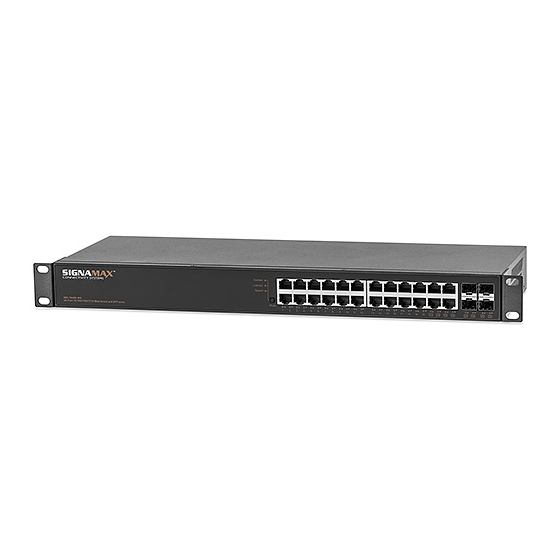
1-4. External View of the Signamax 065-7940D-WS 24-port Gigabit Web Smart Switch Signamax 065-7940D-WS 24-Port Gigabit Ethernet Fig. 1-1 Full View of the Web Smart Switch 1-4-1. User Interfaces on the Front Panel (Button, LEDs and Plugs) There are 24 TP Gigabit Ethernet ports and 4 SFP fiber ports for optional removable modules on the front panel of the switch. -
Page 14: Modules
Signamax 065-7940D-WS 24-Port Gigabit Fig. 1-3 Rear View of Ethernet Web Smart Switch 1-5. Optional SFP Modules In the switch, Port 21~24 include two types of media --- TP and SFP Fiber interfaces; they support 10/100/1000 Mbps TP or 1000 Mbps SFP Fiber with an auto-detection function. 1000 Mbps SFP Fiber transceivers are used for high-speed connection expansion;... -
Page 15: Installation
⇒ Wear a grounding device to avoid the damage from electrostatic discharge ⇒ Be sure that power switch is OFF before you insert the power cord to power source • • • • Installing Optional SFP Fiber Transceivers to the Signamax 065-7940D-WS 24-port Gigabit Web Smart Switch Note: If you have no SFP modules, please skip this section. - Page 16 6, 7, 8 in Gigabit TP) and crossed-over (Cable pin-outs for RJ-45 jack 1, 2, 3, 6 to 3, 6, 1, 2) can be used. It means you do not have to determine them, just plug the cable in. ⇒ Use Cat. 5 grade RJ-45 TP cable to connect to a TP port of the switch and the other end is connected to a network-aware device such as a workstation or a server.
-
Page 17: Cabling Requirements
2-1-2. Cabling Requirements To help ensure a successful installation and keep the network performance good, please take care of the cabling requirement. Cables with worse specification will cause the LAN to work poorly. 2-1-2-1. Cabling Requirements for TP Ports ⇒ For Fast Ethernet TP network connection ... - Page 18 specifications, in which the limitations are the timing requirement from physical signals defined by 802.3 series specification of Media Access Control (MAC) and PHY, and timer from some OSI layer 2 protocols such as 802.1d, 802.1q, LACP and so on. The fiber, TP cables and devices’...
- Page 19 Case1: All switch ports are in the same local area network. Every port can access each other (See Fig. 2-2) *The switch image is a sample only Fig. 2-2 No VLAN Configuration Diagram If VLAN is enabled and configured, each node in the network that can communicate each other directly is bounded in the same VLAN area.
- Page 20 Case 2b: Port-based VLAN (See Fig.2-4). *The switch image is a sample only Fig. 2-4 Port-based VLAN Diagram 1. VLAN1 members could not access VLAN2, VLAN3 and VLAN4 members. 2. VLAN2 members could not access VLAN1 and VLAN3 members, but they could access VLAN4 members.
-
Page 21: Configuring The Management Agent Of 24-Port Gbe Web Smart Switch
Subnet Mask = 255.255.255.0 Default Gateway = 192.168.1.254 Fig. 2-6 • • • • Managing he Signamax 065-7940D-WS 24-port Gigabit Web Smart Switch through an Ethernet Port Before you communicate with the switch, you have to first finish the configuration of the IP address or know the current IP address of the switch. -
Page 22: Ip Address Assignment
Fig. 2-7 the Login Screen for Web 2-1-4. IP Address Assignment For IP address configuration, there are three parameters needed to be filled in. They are IP address, Subnet Mask, Default Gateway and DNS. IP address: The address of the network device in the network is used for internetworking communication. Its address structure looks is shown in the Fig. - Page 23 Bit # 01 2 15 16 Network address Host Class C: IP address range between 192.0.0.0 and 223.255.255.255. Each class C network has a 24-bit network prefix followed 8-bit host address. There are 2,097,152 (2^21)/24 networks able to be defined with a maximum of 254 (2^8 –2) hosts per network.
- Page 24 25 bits All 0s = 128.1.2.128 1 0000000 1 1111111 All 1s= 128.1.2.255 In this diagram, you can see the subnet mask with 25-bit long, 255.255.255.128, contains 126 members in the sub-netted network. Another is that the length of network prefix equals the number of the bit with 1s in that subnet mask.
-
Page 25: Typical Applications
Default gateway: For the routed packet, if the destination is not in the routing table, all the traffic is put into the device with the designated IP address, known as default router. Basically, it is a routing policy. For assigning an IP address to the switch, you just have to check what the IP address of the network will be connected with the switch. - Page 26 Fig. 2-10 Network Connection between Remote Site and Central Site Fig. 2-10 is a system wide basic reference connection diagram. This diagram demonstrates how the switch connects with other network devices and hosts. Publication date: Nov., 2014 Revision A1...
- Page 27 Fig. 2-11 Peer-to-peer Network Connection Fig. 2-12 Office Network Connection...
-
Page 28: Basic Concept And Management
3. Basic Concept and Management This chapter will tell you the basic concept of features to manage this switch and how they work. 3-1. What is Ethernet? Ethernet originated and was implemented at Xerox in Palo Alto, CA in 1973 and was successfully commercialized by Digital Equipment Corporation (DEC), Intel and Xerox (DIX) in 1980. -
Page 29: Logical Link Control (Llc)
IEEE 802.2 LLC Data Link Layer IEEE802.3 CSMA/CD MAC IEEE 802.3 PLS Physical Layer ANSI X3T9.5 PMD IEEE 802.3 Fiber Coaxial/STP/UTP This above diagram shows the Ethernet architecture, LLC sub-layer and MAC sub-layer, which are responded to the Data Link layer, and transceivers, which are responded to the Physical layer in OSI model. - Page 30 response). The DSAP and SSAP pair with some reserved values indicates some well-known services listed in the table below. 0xAAAA SNAP 0xE0E0 Novell IPX 0xF0F0 NetBios 0xFEFE IOS network layer PDU 0xFFFF Novell IPX 802.3 RAW packet 0x4242 STP BPDU 0x0606 0x9898 Table 3-2...
-
Page 31: Media Access Control (Mac)
3-3. Media Access Control (MAC) 3-3-1. MAC Addressing Because a LAN is composed of many nodes, for the data exchanged among these nodes, each node must have its own unique address to identify who should send the data or should receive the data. In the OSI model, each layer provides its own means to identify the unique address in some form, for example, an IP address in the network layer. - Page 32 Start-of-frame delimiter (SFD) — The SFD is one-byte long with alternating pattern of ones and zeros, ending with two consecutive 1-bits. It immediately follows the preamble and uses the last two consecutive 1s bit to indicate that the next bit is the start of the data packet and the left-most bit in the left-most byte of the destination address.
- Page 33 As Ethernet adopted Carrier Sense Multiple Access with Collision Detect (CSMA/CD), it detects if there is any carrier signal from another network device running over the physical medium when a frame is ready for transmission. This is referred to as sensing carrier, also “Listen”. If there is signal on the medium, the MAC defers the traffic to avoid a transmission collision and waits for a random period of time, called backoff time, then sends the traffic again.
- Page 34 Ethernet MAC transmits frames in half-duplex and full-duplex ways. In half-duplex operation mode, the MAC can either transmit or receive frame at a moment, but cannot do both jobs at the same time. As the transmission of a MAC frame with the half-duplex operation exists only in the same collision domain, the carrier signal needs to spend time to travel to reach the targeted device.
- Page 35 Parameter 10Base 100Base 1000Base value/LAN Max. collision 100 meters for UTP 100 meters for UTP domain DTE to 100 meters 412 meters for fiber 316 meters for fiber Max. collision domain with 2500 meters 205 meters 200 meters repeater Slot time 512 bit times 512 bit times 512 bit times...
-
Page 36: Flow Control
3-4. Flow Control Flow control is a mechanism to tell the source device stopping sending frame for a specified period of time designated by target device until the PAUSE time expires. This is accomplished by sending a PAUSE frame from target device to source device. When the target is not busy and the PAUSE time is expired, it will send another PAUSE frame with zero time-to-wait to source device. - Page 37 Frame Reception In essence, the frame reception is the same in both operations of half duplex and full duplex, except that full-duplex operation uses two buffers to transmit and receive the frame independently. The receiving node always “listens” if there is traffic running over the medium when it is not receiving a frame. When a frame destined for the target device comes, the receiver of the target device begins receiving the bit stream, and looks for the PRE (Preamble) pattern and Start-of-Frame Delimiter (SFD) that indicates the next bit is the starting point of the MAC frame until all bit of the frame is received.
- Page 38 0xFFF: Reserved Table 3-5 Note: RIF is used in Token Ring network to provide source routing and comprises two fields, Routing Control and Route Descriptor. When MAC parses the received frame and finds a reserved special value 0x8100 at the location of the Length/Type field of the normal non-VLAN frame, it will interpret the received frame as a tagged VLAN frame.
-
Page 39: How Does A Switch Work
3-5. How does a switch work? The switch is a layer 2 Ethernet Switch equipped with 24 Gigabit Ethernet ports and 4 optional modules which support Gigabit Ethernet or 100M Ethernet. Each port on it is an independent LAN segment and thus has 24 LAN segments and 26 collision domains, contrast to the traditional shared Ethernet HUB in which all ports share the same media and use the same collision domain and thus limit the bandwidth utilization. - Page 40 Fig.3-6 Collision Domain Extended Distance Limitations: The diameter of a half-duplex LAN segment is determined by its maximum propagation delay time. For example, in 10M LAN, the most distance of a LAN segment using yellow cable is 2500 meters and 185 meters when using coaxial cable.
- Page 41 Fig. 3-7 How does a switch operate? A Layer 2 switch uses some features of the Data Link layer in OSI model to forward the packet to the destination port(s). Here we introduce some important features of a switch and how they work. MAC address table When a packet is received on a port of switch, the switch first checks if the packet good or bad and extracts the source MAC address (SA) and destination MAC address (DA) to find 1) if SA is existed in the...
- Page 42 Weighted Round Robin: Set a weight figure to the packet with a priority level, say 5-7, and next, set another weight to the packet with a priority level, say 2-4 and so on. The WRR will transmit the packet with the weight. So the packet of each priority level can be allocated a fixed bandwidth.
-
Page 43: Virtual Lan
3-6. Virtual LAN What is a VLAN? It is a subset of a LAN. Before we discuss VLAN, we must understand what a LAN is. In general, a LAN is composed of different physical network segments bridged by switches or bridges which attach to end stations in the same broadcast domain. - Page 44 Fig. 4-26 Configuration Upload/Download Publication date: Nov., 2014 Revision A1...
-
Page 45: Logout
4-4-5. Logout In addition to auto logout function we just mentioned in system configuration section, the switch also allows administrators to logout manually by Logout function. Function name: Logout Function description: The switch allows you to logout the system to prevent other users from the system without the permission. -
Page 46: Maintenance .....................................................E Rror ! Bookmark Not Defined
5. Maintenance 5-1. Resolving No Link Condition The possible causes for a no link LED status are as follows: The attached device is not powered on The cable may not be the correct type or is faulty The installed building premise cable is faulty The port may be faulty 5-2. -
Page 47: Appendix A Technical Specifications
Appendix A Technical Specifications Features 20 (10/100/1000Mbps) Gigabit Ethernet (TP) switching ports are compliant with IEEE802.3, 802.3u, • 802.3z and 802.3ab. 4 Gigabit TP/SFP fiber are dual media ports with auto detected function. • Non-blocking store-and-forward shared-memory Web-Smart switched. • Supports auto-negotiation for configuring speed, duplex mode. - Page 48 Hardware Specifications Standard Compliance: IEEE802.3/802.3ab / 802.3z / 802.3u / 802.3x Network Interface: Configuration Mode Connector Port 10/100/1000Mbps Gigabit TP 1 - 20 NWay TP (RJ-45) 21 - 24 1000 FDX *SFP 1000BaseSX Gigabit Fiber (Option) 21 - 24 1000 FDX *SFP 1000BaseLX Gigabit Fiber (Option)
- Page 49 Diagnostic LED: System LED : Power Per Port LED: 10/100/1000M TP Port 1 to 20 : LINK/ACT, SPD 1000M SFP Fiber Port 21 to 24 : LINK/ACT, SPD Power Requirement AC Line Voltage 100∼240 V Frequency 50∼60 Hz Consumption Ambient Temperature 0°...
-
Page 50: Appendix Bmib Specifications
Appendix B MIB Specifications MIB II Enterprise MIB brief description is listed as below. For technical support or the latest version of MIB download, please visit our web site at www.signamax.com PRIVATE-GESM-SW24-MIB DEFINITIONS ::= BEGIN IMPORTS mib-2, DisplayString,ifIndex FROM RFC1213-MIB...
Need help?
Do you have a question about the 065-7940D-WS and is the answer not in the manual?
Questions and answers