
Related Manuals for SignaMax 065-7910HPOEP


Summary of Contents for SignaMax 065-7910HPOEP
-
Page 1: User Manual
065-7910HPOEP SIGNAMAX POE+ Series Industrial Ethernet Switches User Manual May 6, 2014 Version: V 1.0... -
Page 2: Revision History
SIGNAMAX POE+ Series Industrial Ethernet Switch Revision History Revision Date Reason for change V1.0 2014.5.6 Initial release... -
Page 3: Table Of Contents
SIGNAMAX POE+ Series Industrial Ethernet Switch Table of Contents 1 Preface ............................ 6 1.1 Conventions ............................ 6 1.2 Device Introduction ........................6 1.2.1 Brief Introduction........................ 6 1.2.2 Features ..........................7 1.2.3 Port Introduction ......................... 7 1.2.4 Indicator Introduction ......................7 1.2.5 Default Configuration ...................... - Page 4 SIGNAMAX POE+ Series Industrial Ethernet Switch 7.1.2 Dynamic Unicast MAC ..................... 35 7.2 Multicast MAC Address ......................35 7.3 IGMP Snooping Configuration ....................37 7.3.1 IGMP Snooping ......................... 38 7.3.2 Route Port ........................... 39 7.3.3 Misc ............................39 8 Security ..........................41 8.1 Management Security .........................
- Page 5 SIGNAMAX POE+ Series Industrial Ethernet Switch 12.3 RecoverRing II™ Timer ......................66 13 SNMP Manager ......................... 68 13.1 SNMP Account ..........................69 13.1.1 SNMP Community ......................69 13.1.2 SNMP User ........................69 13.2 SNMP Trap ........................... 70 13.2.1 Global Trap ........................70 13.2.2 Trap Host IP ........................
-
Page 6: Preface
Ethernet network communication solution. The SIGNAMAX POE+ series’ high availability and reliability, as well as the rich security features make it ideal for data transmission securely. SIGNAMAX POE series provides powerful management capabilities, and can be managed through Web, CLI, Telnet/serial console and SNMP. -
Page 7: Features
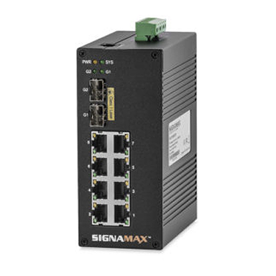
Model Ethernet Port port supply SIGNAMAX 8 X10/100BaseTX port + 2X1000BaseX SFP slots 1X RS232 48VDC 065-7910HPOEP 1.2.4 Indicator Introduction 10/100BaseTX Port Port Indicator Status Description Green On —The port works at 100Mbps. Green Green Off—The port works at 10Mbps. -
Page 8: Default Configuration
1 Preface Green Off—Port Link Down Yellow Blinking—Data is transmitting. Yellow Yellow Off—No data is being transmitted. 100BaseFX port/1000BaseX SFP slots Port Indicator Status Description Green On and Blinking—Port Link Up, date is being transmitted. Green Green On—Port Link Up Green Off—Port Link Down Other Indicators Port Indicator Status... -
Page 9: Login To The Switch
If you need to change the switch IP address at the first time, you can modify it through RS232 console, or using telnet to login, you can refer to “POE Entry-level Series Industrial Switch CLI Guide V1.0”. 1.2.7 WEB Management Overview This manual introduces the SIGNAMAX POE series industrial Ethernet switches by the WEB... - Page 10 1 Preface interface, shown as follows. Menu Function Introduction System Shows the device system information. Information Advanced Enables or disables the main functions. Configuration Port Set port configuration, Aggregation, Bandwidth and Mirroring Management VLAN Configures Port-based VLAN and 802.1Q VLAN, as well as GARP. Configures QoS, Scheduling Mechanism, Transmit Queues and DSCP Map.
-
Page 11: System Information
2System Information 2 System Information The device system information is shown as follows. Through SNMP, you can configure the corresponding system name and system location for each switch for convenient management. -
Page 12: Advanced Configuration
3 Advanced Configuration 3 Advanced Configuration IGMP Snooping, GVRP, STP, LACP, LLDP, 802.1X, RecoverRing II™ and Modbus can be enabled or disabled globally on this page. -
Page 13: Port Management
4 Port Management 4 Port Management You can set port configuration, aggregation, bandwidth and mirroring with this menu. 4.1 Port Configuration At first, you should select a port for configuration. You can cofigure the port state, negotiation, speed and duplex, flow control, MAC learning and MDI/MDIX. Caution: ... -
Page 14: Port Aggregation
Depending on different aggregation modes, aggregation groups fall into three types: manual, static LACP, and dynamic LACP. 4.2.1 Aggregate Groups SIGNAMAX POE series industrial switches supports 13 link aggregation groups. Configuration steps: Step 1 Select Trunk ID. There are 13 groups(T1 ~ T13 );... -
Page 15: Lacp Port Setting
4 Port Management Caution: If LACP (Link Aggregation Control Protocol) is disabled in Advanced Configuration, you can only configure port aggregration manually, so If you want to configure port aggregation statically, you need to enable LACP in Advanced Configuration. ... -
Page 16: Aggregate Basic Setting
MAC address, that is, device ID = system priority + system MAC address. When two device SIGNAMAX are compared, the system priorities are compared first, and the system MAC addresses are compared when the system priorities are the same. The device with smaller device ID will be considered as the preferred one. -
Page 17: Port Bandwidth
4 Port Management 4.3 Port Bandwidth You can configure the egress traffic limit on individual ports, so as to keep normal network service. The bottom of the page will show the rate limit list. Port: Select the port to configure Egress: The desired egress rate limit to be configured. - Page 18 4 Port Management Port mirroring refers to the process of copying the packets received or sent by the specified port to the destination port for packet analysis and monitoring. Generally, a destination port is connected to a data detect device, which users can use to analyze the mirrored packets for monitoring and troubleshooting the network, shown as the following figure: Configuration steps: Step 1 Enable/disable mirroring state;...
-
Page 19: Poe
4 Port Management 4.5 POE POE (Power Over Ethernet) is referred to a technology as the existing Ethernet cabling infra structure Cat.5 which do not make any changes, transmits data signals for some IP-based t erminals(such as IP telephones, wireless LAN access point AP, network cameras etc.) , mea nwhile provids DC power supply technology for such equipments. - Page 20 4 Port Management (2)POE Port settings POE Mode: Three selections: POE, POE+ and shut down. POE mode in accordance with the IEEE 802.3 AF protocol transmission, provide up to 15.4W power supply for each POE port; POE+ model in accordance with the IEEE 802.3 AT protocol transmission, provide up to 30W power supply for each POE port;...
-
Page 21: Vlan
5 VLAN 5 VLAN The traditional Ethernet is a broadcast network, where all hosts are in the same broadcast domain and connected with each other through hubs or switches. The hub is a physical layer device without the switching function, so it forwards the received packet to all ports. The switch is a link layer device which can forward the packet according to the MAC address of the packet. -
Page 22: Advanced
5 VLAN 5.1 Advanced This page globally sets the VLAN mode from the following: NO VLAN, port-based VLAN and 802.1Q VLAN. 5.2 Port-based VLAN Port-based VLAN technology introduces the simplest way to classify VLANs. You can isolate the hosts and divide them into different virtual workgroups through assigning the ports on the device connecting to hosts to different VLANs. -
Page 23: 802.1Q Vlan
TPID is a 16-bit field, indicating that this data frame is VLAN-tagged. By default, it is 0x8100 in First Mile SIGNAMAX POR series Ethernet industrial switches. Priority is a 3-bit field, referring to 802.1p priority. Refer to section “QoS & QoS profile” for... -
Page 24: 802.1Q Vlan Setting
5 VLAN CFI is a 1-bit field, indicating whether the MAC address is encapsulated in the standard format in different transmission media. VLAN ID is a 12-bit field, indicating the ID of the VLAN to which this packet belongs. It is in the range of 0 to 4,095. -
Page 25: 802.1Q Configuration
5 VLAN 5.3.2 802.1Q Configuration This tab page configures a VLAN group; each port can be configured as a specific state for this VLAN group: Tag:Indicates the port is a tagged member of the VLAN group. All packets forwarded by the port are tagged. -
Page 26: Garp Setting
5 VLAN user PCs. Tag is deleted when transmitting packets. Trunk: A trunk port can belong to more than one VLAN. It can receive/send packets from/to multiple VLANs, and is generally used to connect another switch. A trunk port can belong to multiple VLANs, but it can only be configured as untagged in one VLAN. -
Page 27: Garp
5 VLAN that all the switching devices in the same switched network can have the same VLAN information. The VLAN registration information includes not only the static registration information configured locally, but also the dynamic registration information received from other switches. ... -
Page 28: Gvrp
5 VLAN 5.4.2 GVRP GVRP (GARP VLAN Registration Protocol) is an implementation of GARP (generic attribute registration protocol). GVRP allows the switch to automatically add or remove the VLANs via the dynamic VLAN registration information and propagate the local VLAN registration information to other switches, without having to individually configure each VLAN. - Page 29 5 VLAN...
-
Page 30: Qos
6 QoS 6 QoS In data communications, Quality of Service (QoS) is the ability of a network to provide differentiated service guarantees for diversified traffic in terms of bandwidth, delay, jitter, and drop rate. On traditional IP networks, devices treat all packets equally and handle them using the first in first out (FIFO) policy. -
Page 31: Scheduling Mechanism
6 QoS Port-based Priority:There is 8 priorities from 0 to 7. DSCP:Enable or disable DSCP The lower part of QoS Configuration tab page lists the default priority of all ports and the state of DSCP. 6.2 Scheduling Mechanism This page sets the queue scheduling algorithm and related parameters. Scheduling Mechanism: Can be set to Strict Priority or Weighted Round-Robin (WRR) Strict Priority: SP queue-scheduling algorithm is specially designed for critical service applications. -
Page 32: Transmit Queues
6 QoS advantage of WRR queue is that: though the queues are scheduled in order, the service time for each queue is not fixed; that is to say, if a queue is empty, the next queue will be scheduled. In this way, the bandwidth resources are made full use. 6.3 Transmit Queues This page sets the 802.1p priority to local precedence mapping. - Page 33 6 QoS...
-
Page 34: Forwarding
7 Forwarding 7 Forwarding SIGNAMAX POE series industrial switch has unicast MAC address forwarding and multicast MAC address forwarding, the introduction is followed. 7.1 Unicast MAC Address MAC address forwarding table: the device forwards the packets to the corresponding port according to the packet destination MAC address. -
Page 35: Dynamic Unicast Mac
7 Forwarding Caution: The port must be a member of this VLAN. The port should not be a member of a trunk group. 7.1.2 Dynamic Unicast MAC This page lists all dynamic unicast MAC addresses, including learned by the switch and added manually. - Page 36 7 Forwarding The advantages of multicast are summarized as follows: Over unicast: As multicast traffic flows to the node the farthest possible from the source before it is replicated and distributed, an increase of the number of hosts will not increase the load of the source and will not remarkably add to network resource usage.
-
Page 37: Igmp Snooping Configuration
7 Forwarding Caution: Multicast source maybe doesn’t belong to the multicast group, that is to say, it is not necessarily the receiver of multicast data; A multicast source can transmit packets to multiple multicast groups at the same time, while several multicast source can also send packets to the same multicast group. -
Page 38: Igmp Snooping
7 Forwarding data based on these mappings. As shown in the following figure, when IGMP Snooping is not running on the device, multicast packets are broadcast to all devices at Layer 2. When IGMP Snooping is running on the switch, multicast packets for known multicast groups are multicast to the receivers, rather than broadcast to all hosts, at Layer 2. -
Page 39: Route Port
7 Forwarding 7.3.2 Route Port On this page, you can configure a port in a specified VLAN group as a static router port. By default, a port is not a static router port. If a port is fixed to receive the packets from a multicast group, it can be configured to join in the multicast group statically, so that the device can receive IGMP message by the port from router. - Page 40 7 Forwarding be deleted from the router port list. It is in the range of 1 to 1000; by default, the value is 105 seconds. IGMP Querier: IGMP Querier sends IGMP general query packets to all the hosts and router ports in the network segment to check the multicast group members.
-
Page 41: Security
8 Security 8 Security It mainly introduces Management Security, Port Authentication, MAC Authentication and Storm Control. The 802.1x protocol (802.1x for short) was developed by IEEE802 LAN/WAN committee to address security issues of wireless LANs. It was then used in Ethernet as a common access control mechanism for LAN ports to address mainly authentication and security problems. -
Page 42: Port Authentication
8 Security shared key. 8.2 Port Authentication IEEE 802.1x authentication system uses extensible authentication protocol (EAP) to exchange information between supplicant systems and the authentication servers. When a supplicant system passes the authentication, the authentication server passes the information about the supplicant system to the authenticator system. The authenticator system in turn determines the state (authorized or unauthorized) of the controlled port according to the instructions (accept or reject) received from the RADIUS server. -
Page 43: 802.1X Port
8 Security send feedbacks (through a RADIUS access-accept packet and an EAP-success packet) to the switch to indicate that the supplicant system is authenticated. The switch changes the state of the corresponding port to accepted state to allow the supplicant system to access the network. -
Page 44: 802.1X Misc
8 Security access network resources in a restrained way. It enables supplicant systems that do not have 802.1x client installed to access specific network resources. It also enables supplicant systems that are not authenticated to upgrade their 802.1x client programs. With this function enabled: ... -
Page 45: Mac Authentication
8 Security function. In this case, this timer sets the interval to send the multicast request/identity packets. It is in the range of 1 to 65535; the default value is 30 seconds. Supplicant Timeout: Set the supplicant system timer, this timer sets the supp-timeout period and is triggered by the switch after the switch sends a request/challenge packet to a supplicant system. -
Page 46: Port Configuration
8 Security MAC address authentication is port- and MAC address-based authentication used to control user permissions to access a network. MAC address authentication can be performed without client-side software. With this type of authentication employed, a switch authenticates a user upon detecting the MAC address of the user for the first time. -
Page 47: Authentication Information
8 Security 8.3.3 Authentication Information This page lists all the MAC authentication information including MAC Address, From Port, and Authenticate state. 8.4 Storm Control Traffic storm will be generated when there are multiple broadcast / multicast / DLF (Destination Lookup Failed) packets passing through a port, thus it will lead to traffic congestion. -
Page 48: Lldp
9 LLDP 9 LLDP Note: Enable LLDP in 3 Advanced Configuration. In a heterogeneous network, it is important that different types of network devices from different vendors can discover one another and exchange configuration for interoperability and management sake. Therefore, a standard configuration exchange platform was created. The IETF drafted the Link Layer Discovery Protocol (LLDP) in IEEE 802.1AB. - Page 49 9 LLDP Field Description Destination The MAC address to which the LLDPDU is advertised. It is address fixed to 0x0180-C200-000E, a multicast MAC address. The MAC address of the sending port. If the port does not Source MAC address have a MAC address, the MAC address of the sending bridge is used.
- Page 50 9 LLDP LLDPDUs encapsulated with same encapsulation format. SNAP-encapsulated LLDPDU. LLDPDU encapsulation format is Ethernet II by default. If the neighbor devices encapsulates LLDPDU with SNAP format, the user can change the LLDPDU encapsulation format to SNAP to maintain the normal communication with neighbor devices. LLDP can operate in one of the following modes: Disabled mode A port in this mode does not send or receive LLDPDUs.
-
Page 51: Tlvs
9 LLDP Caution: The port should not be a member of a trunk group. 9.1.2 TLVs TLVs are type, length, and value sequences that carry information elements. The type field identifies the type of information, the length field measures the length of the information field in octets, and the value field contains the information itself. -
Page 52: Neighbor Information
9 LLDP and the default value is 4. Tx Delay:The delay period between successive LLDP packets which are initiated by port parameter changes. The range is from 1 to 8192, and the default value is 2. Re-init Delay:in the case of LLDP Status mode changes, the port will initialize the protocol state machine, and the switch will need to wait for Re-init Delay to be able to start the next initialization. - Page 53 9 LLDP...
-
Page 54: Statistics
10 Statistics 10 Statistics It shows the following items: 10.1 Port Status This page shows the State, Media, Link, Negotiation, Speed & Duplex, Flow Control, Learning and MDI/MDIX of each Ethernet port. 10.2 Port Statistics This page shows the TxGoodPkts, TxBadPkts, RxGoodPkts, RxBadPkts, TxAbort, Collision, and DropPkt of each Ethernet port. -
Page 55: Vlan List
10 Statistics TxFCSErr: The number of FCS (Frame Check (Checking) Sequence) packets Collision: The number of detected collisions DropPkt: The number of packets dropped for various reasons 10.3 VLAN List This page lists the information of all VLANs, including VID, Name, Type, Tagged ports, Untagged ports, and Forbidden ports. -
Page 56: Link Aggregation
10 Statistics This page shows IGMP Snooping multicast group information. 10.6 Link Aggregation 10.6.1 Manual Trunking Group This page shows manual trunking information, including Trunk ID, Trunk Name, Type, and Port List. Type is fixed to Manual. 10.6.2 Static Trunking Group This page shows static trunk information, including Trunk ID, Trunk Name, Type, and Port List. -
Page 57: Spanning Tree
11 Spanning Tree 11 Spanning Tree 1. Purpose of STP Spanning tree protocol (STP) is a protocol conforming to IEEE 802.1d. It aims to eliminate loops on data link layer in a local area network (LAN). Devices running this protocol detect loops in the network by exchanging packets with one another and eliminate the loops detected by blocking specific ports until the network is pruned into one with a tree topology. -
Page 58: Stp
11 Spanning Tree directly connected to a switch and is designated bridge forwards responsible for forwarding BPDUs to this BPDUs to this device switch. The port through which the A designated bridge is a device responsible For a LAN designated bridge forwards for forwarding BPDUs to this LAN segment. -
Page 59: Basic Stp
11 Spanning Tree Note: Enable STP in 3 Advanced Configuration. 11.1.1 Basic STP The following factors should be considered when setting STP configuration: Priority:The priority of switch, it ranges from 0 to 65535, and the default value is 32768. The smaller the value is, the higher the priority is. -
Page 60: Stp Information
11 Spanning Tree 11.1.2 STP Information This page lists basic information of Designated Bridge, including Bridge ID, Root Bridge ID, Root Port, and Root Path Cost. Bridge ID ID of designated switch, designated bridge priority plus MAC address Root Bridge ID ID of the root bridge, consisting of root bridge priority and MAC address Root Port The spanning tree root port. -
Page 61: Rstp
11 Spanning Tree 11.2 RSTP Note: Enable STP in 3 Advanced Configuration, the STP parameters are still effective. Rapid spanning tree protocol (RSTP) is an optimized version of STP. RSTP allows a newly elected root port or designated port to enter the forwarding state much quicker under certain conditions than in STP. - Page 62 11 Spanning Tree to another switch. But, in case that BPDU protection function is disabled on an edge port, configuration BPDUs sent deliberately by a malicious user may reach the port. If an edge port receives a BPDU, it changes itself to be a non-edge port. Caution : RecoverRing II™...
-
Page 63: Recoverring Ii™ Configuration
12 RecoverRing II™ Configuration 12 RecoverRing II™ Configuration Note: Enable RecoverRing II™ in 3 Advanced Configuration. But STP cannot be enabled with RecoverRing II™ at the same time. RecoverRing II™ is a link layer protocol. It can prevent broadcast storm when the Ethernet ring is complete, while it can recover the communication among each nodes when one link is down on the Ethernet ring. -
Page 64: Recoverring Ii
12 RecoverRing II™ Configuration A RecoverRing II™ domain has a RecoverRing II™ primary ring, control VLAN, mater node, transit node, primary port, secondary port, public port and edge port and so on. As shown in the above figure, there are two rings: ring 1 and ring 2. They can comprise network with coupling and dual homing. -
Page 65: Recoverring Ii™ Coupling
12 RecoverRing II™ Configuration Secondary port: The master node uses it to receive RecoverRing II™ packets. Block it to prevent flooding, while unblock it when a link failure has occurred. The primary and secondary ports of a transit node have the same functions. The bottom part of this page lists the configuration of each of the two rings. -
Page 66: Recoverring Ii™ Timer
12 RecoverRing II™ Configuration 1. Two directly connected rings cannot have the same Ring ID. 2. Within a ring, only one switch can be set as Coupling Primary, and the other one as Coupling Backup. 3. Within the same level ring, more than one switch can be set as Dual homing. The bottom part of this page lists the configuration of two coupling rings. - Page 67 12 RecoverRing II™ Configuration To set those parameters, the following rules shall be met: 3* HelloTime < =FailTime and 3* FastHelloTime <= FastFailTime.
-
Page 68: Snmp Manager
SIGNAMAX POE series industrial switch SNMP agents support three SNMP versions: SNMPv1, SNMPv2c, and SNMPv3. SNMPv1 uses Community Name authentication to control access to SNMP agents. SNMPv1 Community Name falls into “read only”... -
Page 69: Snmp Account
13 SNMP Manager SNMP Management Station is the manager of SNMP network while SNMP Agent is the managed object. The information between SNMP Management Station and SNMP Agent are exchanged through SNMP (Simple Network Management Protocol). The relationship among SNMP Management Station, SNMP Agent and MIB is illustrated in the following figure. 13.1 SNMP Account 13.1.1 SNMP Community Create SNMP account. -
Page 70: Snmp Trap
13 SNMP Manager SNMP V3 Encryption: Click to enable SNMP V3 Encryption. If SNMP V3 Encryption is not selected, neither encryption nor authentication will be performed. Auth Algorithm: Select the Authentication Algorithm for the SNMP v3 User. MD5: The authentication is performed via HMAC-MD5 algorithm. SHA: The authentication is performed via SHA (Secure Hash Algorithm). -
Page 71: Trap Port
13 SNMP Manager This tab page specifies SNMP trap Host IP. Host IP is the IPv4 address of the host to receive the traps. The bottom part of this page lists all existing trap host IP addresses. They can be deleted. 13.2.3 Trap Port Enable or disable the trap function for each port. -
Page 72: Rmon
14 RMON 14 RMON Remote Monitoring (RMON) is used to realize the monitoring and management from the management devices to the managed devices on the network by implementing such functions as statistics and alarm. The statistics function enables a managed device to periodically or continuously track various traffic information on the network segments connecting to its ports, such as total number of received packets or total number of oversize packets received. - Page 73 14 RMON Broadcastkts: The total number of the received good packets that are directed to the broadcast address, except the multicast packets. MulticastPkts: The total number of the received good packets that are directed to a multicast address, except the packets directed to the broadcast address. CRC Align Errors: The total number of the received packets that has a length (excluding framing bits, but including FCS octets) of between 64 and 1518 octets (both inclusive), and has either a bad FCS with an integral number of octets (FCS Error) or a bad FCS with a...
-
Page 74: History
14 RMON Drop Events: The total number of events when packets are dropped by the probe due to lack of resources. All of the statistics for each Ethernet port can be reset. 14.2 History 14.2.1 History control This page sets a history control entry on each port. And then the port will be sampled with the specified interval and the specified sample number about its transmitting situation. -
Page 75: History List
14 RMON 14.2.2 History List On this page, one of the history can be selected to show the relate statistics. The lower part of this page shows the related statistics information: DropEvents RxOctets, RxPkts, Broadcast, Multicast, CRC AlignErrors, Undersize, Oversize, Fragments, Jabbers, Collisions and Utilization. - Page 76 14 RMON the thresholds at the end of the sampling interval. If the value of this object is deltaValue (2), the value of the selected variable at the last sample will be subtracted from the current value, and the difference will be compared with the thresholds. RMON alarm can monitor the specified alarm variables.
-
Page 77: Event Configuration
14 RMON value is less than or equal to this threshold, and the last sample value was greater than this threshold, a single event will be generated. A single event will also be generated if the first sample, after this entry becomes valid, is less than or equal to this threshold and the associated StartupAlarm is equal to fallingAlarm (2) or risingOrFallingAlarm (3). -
Page 78: Event
14 RMON The event group defines event indexes and controls the generation and notifications of the events triggered by the alarms defined in the alarm group. 14.4.1 Event Configuration Steps: Step 1 Specify the community. If an SNMP trap is to be sent, it will be sent to the SNMP community specified by this octet string. -
Page 79: Administration
15 Administration 15 Administration 15.1 Language There are two languages: Chinese and English. After clicking <Apply>, it will turn to the [System Information] page. 15.2 IP Configuration The switch supports DHCP and Static IP. DHCP Client can be enabled by checking the Enabled checkbox, the switch get IP address from DHCP server. -
Page 80: Smtp
15 Administration 15.4 SMTP This page sets SMTP configuration. When a pre-defined event occurs, an e-mail will be sent to the following destination mail address. Destination Mail: The e-mail address to receive the event information. SMTP Service IP: The IP address of SMTP server. Source Account Name: Source e-mail account on SMTP server. -
Page 81: Port Event
15 Administration Onaccess cold start: Enable or disable to trigger an e-mail alarm when the switch is booted up by turning on the power. Onaccess warm start: Enable or disable to trigger an e-mail alarm when the switch is restarted without turning off power. Auth failure: Enable or disable to trigger an e-mail alarm when it fails to login to the switch due to incorrect username or password. -
Page 82: Relay Alarm
15 Administration The bottom part of this tab page lists all port events. 15.6 Relay Alarm This page sets Relay Alarm event, including System Event and Port Event. When an event occurs, the relay output will be closed for external devices and an alarm indicator, for example, takes action. -
Page 83: System Log
15 Administration Alarm Type: If it is enabled, there are three alarm types for the event: Link Up, Link Down, and Up & Down. Traffic Overload: It means that the port traffic exceeds Traffic Threshold during a statistics time of Traffic Duration. Traffic Threshold: The threshold for port traffic (in percentage of the port speed). -
Page 84: Ping Diagnosis
15 Administration 15.8 Ping Diagnosis Ping Diagnosis is a commonly used tool for diagnosing a network problem. Type an IP address in the textbox, and then click <Apply>. The Ping result will be displayed in the following page. If the IP can be reached, it says “This ip is alive!”; Otherwise it says “Cannot reach the destination host.”... -
Page 85: Tftp Services
The TFTP service mentioned in this section refers to TFTP client function of switch. When an SIGNAMAX POE series Ethernet industrial switch serves as a TFTP client to download files from TFTP server and when you download a file that is larger than the free space of the switch’s memory:... -
Page 86: Backup Configuration
15 Administration This page sets a TFTP Server IP and Firmware Name. Before doing firmware upgrade, make sure the switch is connected to the TFTP server and firmware file exists on the server. The switch will begin to update firmware after <Apply> button is clicked. 15.10.2 Backup Configuration This page sets a TFTP Server IP and File Name. -
Page 87: Reset
15 Administration Reboot Without Save Directly reboots without saving the current configuration. All changes may be lost. 15.12 Reset There are two tab pages: Reset and Reset To Default. Reset: The switch will be reset to the factory default setting, except that the IP address and user accounts are kept unchanged. -
Page 88: Logout
16 Logout 16 Logout Click <Logout> on the left menu to log out from the switch and close the browser. -
Page 89: Appendix A Supported Mibs
SIGNAMAX POE series Ethernet industrial switch. MIB List RFC1213-MIB RFC1643-EtherLike-MIB RFC1573-IF-MIB RFC1493-BRIDGE-MIB RFC2674-P-BRIDGE-MIB FMC-SWITCH-MIB RFC1757-RMON-MIB RFC2674-Q-BRIDGE-MIB FMC-IGMP-SNOOPING-MIB RSTP-MIB FMC-SWITCH-MAC-AUTHENTICATION-MIB. FMC-SWITCH-RADIUS-MIB IEEE8021-PAE-MIB LLDP-MIB Note: SIGNAMAX 065-7910HPOEP supports up to 2 1000Base SFP slots. Please refer to www.Signamax.com for available SFP modules.
Need help?
Do you have a question about the 065-7910HPOEP and is the answer not in the manual?
Questions and answers