Table of Contents
Advertisement
Quick Links
Advertisement
Table of Contents

Related Manuals for Kichler Lighting 54 inch Skye


Summary of Contents for Kichler Lighting 54 inch Skye
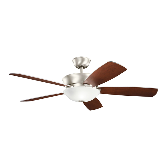
- Page 1 54" Skye 300167 A Kichler Decor ceiling fan ® ™ Includes wall mount control system Kichler Lighting ® 7711 East Pleasant Valley Road P.O. Box 318010 Instruction Manual Cleveland, Ohio 44131-8010 Customer Service 866.558.5706 8:30 AM to 5:00 PM EST, Monday - Friday 3066708...
-
Page 2: Safety Rules
1. SAFETY RULES 1. To reduce the risk of electric shock, insure 10. Do not use water or detergents when electricity has been turned off at the circuit cleaning the fan or fan blades. A dry dust breaker or fuse box before beginning. cloth or lightly dampened cloth will be suitable for most cleaning. -
Page 3: Tools And Materials Required
54" Skye 2. TOOLS AND MATERIALS REQUIRED Philips screw driver Blade screw driver 11 mm wrench Step ladder Wire cutters 3. PACKAGE CONTENTS Unpack your fan and check the contents . You should have the following items: Mounting bracket Ball / downrod assembly (1) Canopy Canopy Hole Cover Coupling cover... -
Page 4: Mounting Options
4. MOUNTING OPTIONS If there isn't an existing ETL listed mounting box, then read the following instructions. Disconnect the power by removing fuses or turning off circuit breakers. Secure the outlet box directly to the building structure. Use appropriate fasteners and Outlet box building materials. -
Page 5: Hanging The Fan
54" Skye 5. HANGING THE FAN ETL Listed Outlet Box REMEMBER to turn off the power before you begin installation. This is necessary for your Ceiling Mounting Bracket safety and also the proper programming of Flat Washer the control system. Screw Screw To properly install your ceiling fan, follow the... -
Page 6: Installation Of Safety Support
Step 5. Now lift the motor body into position and place the hanger ball into the hanger bracket. Rotate until the "Check Tab" has Check Tab Registration Slot dropped into the "Registration Slot " and seats firmly. ( Fig. 9) The entire motor body should not rotate is this is done correctly. -
Page 7: Make The Electric Connections
54" Skye 7. MAKE THE ELECTRIC CONNECTIONS WARNING: To avoid possible electrical shock, be sure you have turned off the power at the main circuit panel before wiring. Follow the steps below to connect the fan to your household wiring. Use the wire connecting nuts supplied with your fan. -
Page 8: Finishing The Installation
Step 3. Remote Receiver to Outlet Box Electrical Connections: Connect the BLACK (hot) wire from the ceiling to the BLACK wire marked “AC in L” from the receiver . Connect the WHITE ( neutral ) wire from the ceiling to the WHITE wire marked “... -
Page 9: Attaching The Fan Blades
54" Skye Canopy Hole Cover Step 3. Securely attach and tighten the canopy Shoulder Screw hole cover over the shoulder screws in the mounting bracket utilizing the keyslot twist-lock feature. (Fig. 17) Fig. 17 Step 4. Install two (2) lamps 50W (included), one in each socket as shown. -
Page 10: Installing The Mounting Plate
Step 2. Fasten blade assembly to the holes located on the bottom of the flywheel. Tighten the two "pre- installed" motor screws in the Motor Body blade arm. Repeat steps for the remaining Flywheel blades assemblies. (Fig. 20) Blade Assembly Motor Screw Fig. -
Page 11: Installing The Transmitter
54" Skye Step 2. Tuck the connections neatly into the light kit. Align the slot holes on the light kit and switch housing. Rotate the light kit until it locks in place at the narrow end of the key holes. Securely by tightening the 2 screws Switch Housing previously loosened and the one previously removed. -
Page 12: Control System Set-Up
Outlet Box Step 1. Remove the existing wall plate and the old switch from the wall outlet box. Wire Switch nut the BLACK leads (hot) together and Wall Plate push back inside the outlet box. (Fig. 26) Or Select the desired location with a new wall outlet box. - Page 13 54" Skye Step 3. You can leave the frequency switches at the factory setting. Or you have to change the dip switch setting in the remote if you are using more than one fan in the same area and Code Switch want to control them separately.
-
Page 14: Troubleshooting
16. TROUBLESHOOTING Problem Solution Fan will not start. 1. Check circuit fuses or breakers. 2. Check all electrical connections to insure proper contact. CAUTION: Make sure the main power is OFF when checking any electrical connection. 3. Make sure the transmitter batteries are installed properly. Positive (+) side facing out.
Need help?
Do you have a question about the 54 inch Skye and is the answer not in the manual?
Questions and answers